QFX5220 Management Panel
The management panel allows you to have a management channel into the switch that is separate from production traffic.
QFX5220-128C Management Panel Overview
The management panel of the QFX5220-128C is located to the right of the network ports. Figure 1 shows the connections and components of the management panel and the network ports.
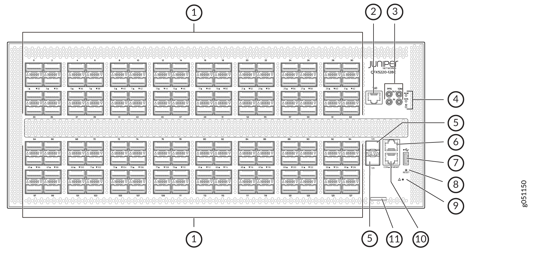
1 — Network ports or port panel, 128 ports of QSFP28 | 7 — USB port for image updates |
2 — RJ-45 grandmaster time-of-day connection | 8 — Reset button (do not use unless under the direction of JTAC) |
3 — PTP capable connections: pulses per second (PPS) Out , PPS In, 10 MHz Out, 10 MHz In | 9 — ESD connection point |
4 — Chassis alarms LEDs | 10 — RJ-45 (1000BASE-T) management Ethernet (MGMT port for the re0:mgmt-0 management interface) |
5 — 1-Gbps or 10-Gbps ports, 2 ports of SFP+ | 11 — Slide-out tab for chassis serial number |
6 — RJ-45 console (CON) port |
QFX5220-32CD Management Panel Overview
The management panel of the QFX5220-32CD is divided in two sections, with the port panel in between these sections. Figure 2 shows the connections and components of the management panel and the network ports.
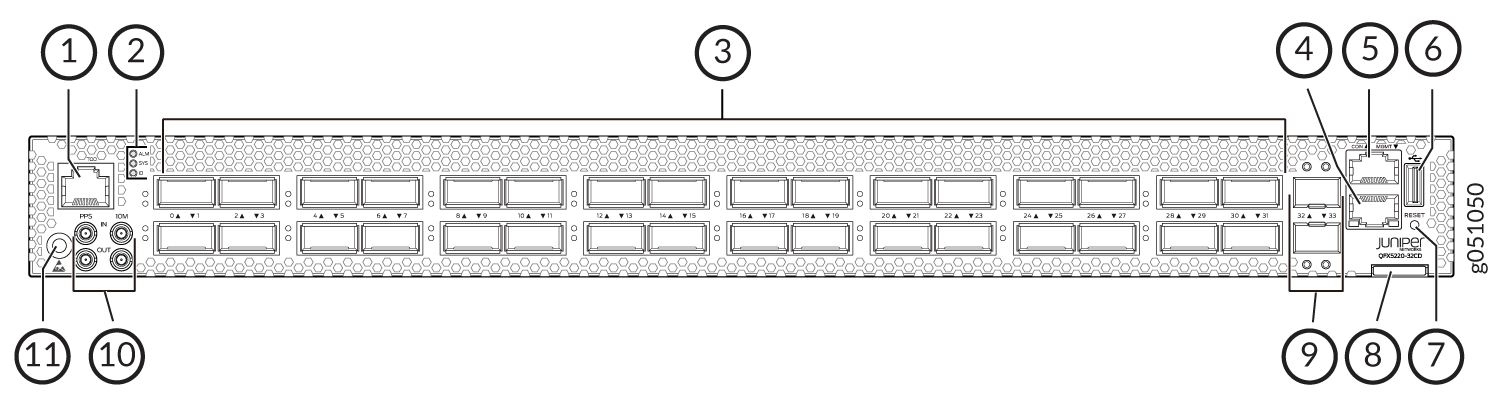
1 — RJ-45 grandmaster time-of-day connection | 7 — Reset button (do not use unless under the direction of JTAC) |
2 — Chassis alarms LEDs | 8 — Slide out tab for chassis serial number |
3 — Network ports or port panel, 32 ports of QSFP-DD | 9 — Network ports, 10-Gigabit Ethernet ports |
4 — RJ-45 (1000BASE-T) management Ethernet (MGMT port for the re0:mgmt-0 management interface) | 10 — PTP and external clock connections |
5 — RJ-45 console (CON) port | 11 — ESD connection point |
6 — USB port for image updates |
QFX5220-32CD Management Panel LEDs
You can find LEDs on these management panel ports:
-
Chassis status LEDs
-
RJ-45 Console and Management Port LEDs
The following sections explain how to interpret these LEDs.
QFX5220 Chassis Status LEDs
Both models of the QFX5220 have a series of three LEDs that indicate system status. On the QFX5220-128C, you can find these LEDs to the right of the network ports (see Figure 3). On the QFX5220-32CD, you can find these LEDs to the left of the network ports (see Figure 4).
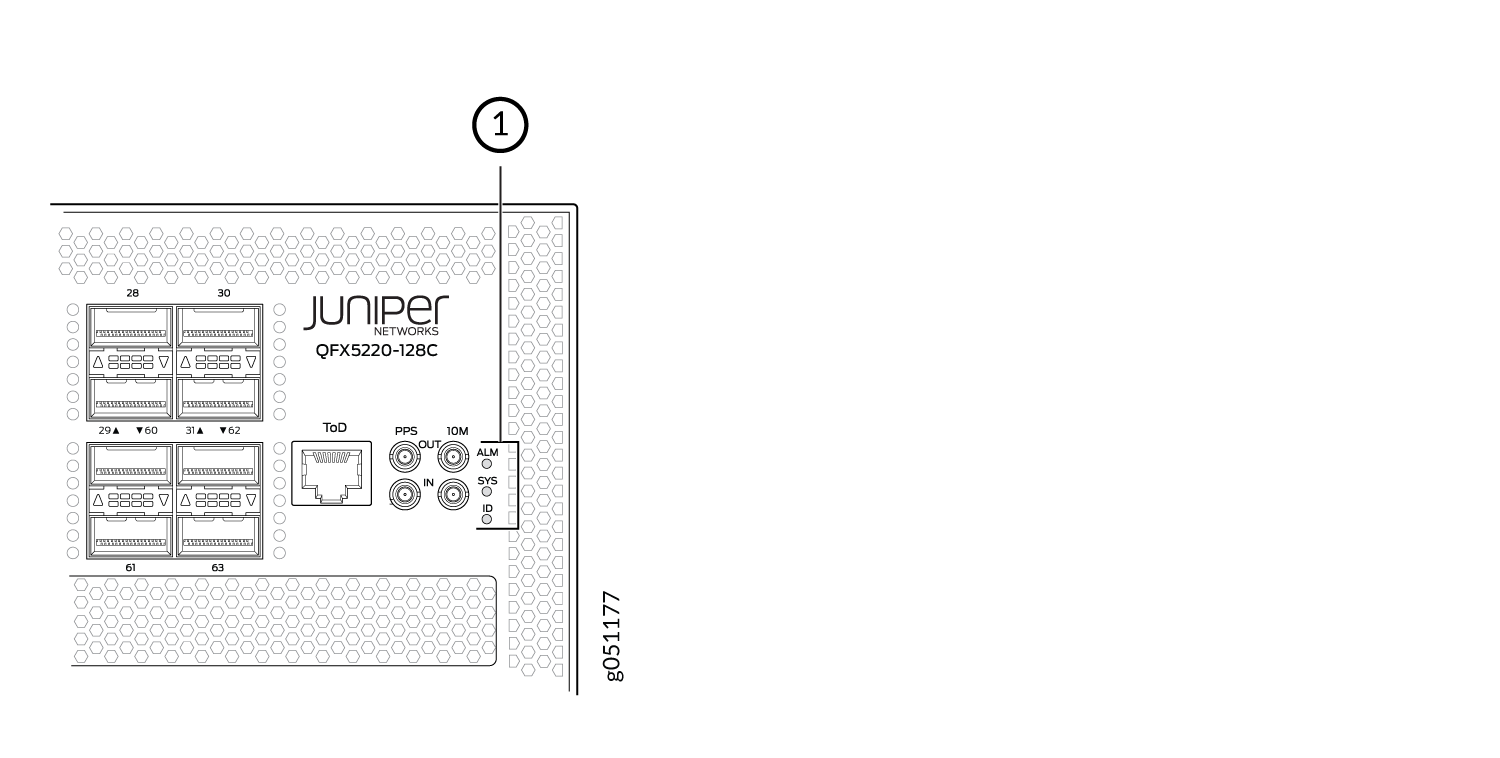
1 — ALM—Chassis alarm or faultSYS—System statusID—Beacon |
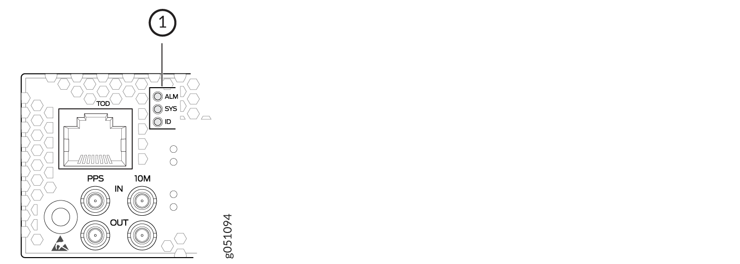
1 — ALM—Chassis alarm or faultSYS—System statusID—Beacon |
Table 1 describes
the chassis status LEDs on a QFX5220, the colors and states, and the
status they indicate. You can view the colors of the three LEDs remotely
through the CLI by issuing the operational mode command show
chassis lcd.
user@host> show chassis led
 -----------------------------------
LEDs status:
    Alarm LED : Red
    Beacon LED: Off
    System LED: Green

Interface               STATUS LED      LINK/ACTIVITY LED
---------------------------------------------------------
et-0/0/0                N/A             Off
et-0/0/1                N/A             Off
et-0/0/2                N/A             Off
et-0/0/3                N/A             Off
et-0/0/4                N/A             Off
et-0/0/5                N/A             Off
et-0/0/6                N/A             Off
et-0/0/7                N/A             Off
et-0/0/8                N/A             Off
et-0/0/9                N/A             Off
et-0/0/10               N/A             Green
et-0/0/11               N/A             Off
et-0/0/12               N/A             Off
et-0/0/13               N/A             Off
et-0/0/14               N/A             Off
et-0/0/15               N/A             Off
et-0/0/16               N/A             Green
et-0/0/17               N/A             Off
et-0/0/18               N/A             Green
et-0/0/19               N/A             Off
et-0/0/20               N/A             Off
et-0/0/21               N/A             Off
et-0/0/22               N/A             Off
et-0/0/23               N/A             Off
et-0/0/24               N/A             Off
et-0/0/25               N/A             Off
et-0/0/26               N/A             Green
et-0/0/27               N/A             Green
et-0/0/28               N/A             Green
et-0/0/29               N/A             Off
et-0/0/30               N/A             Green
et-0/0/31               N/A             Off
et-0/0/32               N/A             Off
et-0/0/33               N/A             Off
|
Name |
Color |
State |
Description |
|---|---|---|---|
|
ALM–Alarm |
Unlit |
Off |
The switch is halted or there is no alarm. |
|
Red |
On steadily |
A major hardware fault has occurred, such as a temperature alarm, power failure, or media failure. The device has halted. Power off the device by setting the AC power source outlet to the OFF (O) position, or unplugging the AC power cords. Correct any voltage or site temperature issues, and allow the switch to cool down. Power on the QFX5220. Monitor the power supply and fan LEDs to help determine where the error is occurring. |
|
|
Amber |
On steadily |
A minor system level alarm has occurred, such as a software error or a missing rescue configuration. Power off the device by setting the AC power source outlet to the OFF (O) position, or unplugging the AC power cords. Power on the QFX5220 and monitor the status LEDs to ensure that Junos OS Evolved boots properly. |
|
|
SYS–System |
Unlit |
Off |
The device is powered off or halted. |
|
Green |
On steadily |
Junos OS Evolved is loaded on the device. |
|
|
ID–Identification |
Unlit |
Off |
The beacon feature is not enabled on the switch. Enable this
feature by using the |
|
Blue |
Blinking |
The beacon feature is enabled on the switch. Disable this feature
by using the |
|
|
Tip:
To find the status of the beacon, use the user@host> show chassis beacon fpc 0
FPC 0 OFF
|
|||
RJ-45 Management Port LEDs
The management port on a QFX5220-32CD has two LEDs that indicate link status and link activity. The management port is labeled MGMT for 10/100/1000BASE-T connections.
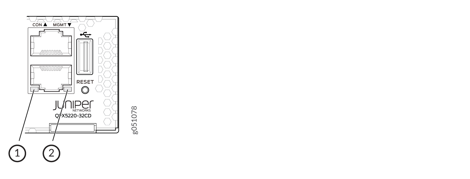
1 — Link and activity LED | 2 — Status LED |
Table 2 describes the management port LEDs.
|
LED |
Color |
State |
Description |
|---|---|---|---|
|
Link/Activity |
Unlit |
Off |
No link is established, there is a fault, or the link is down. |
|
Green |
On steadily |
A link is established, but there is no link activity. |
|
|
Blinking or flickering |
A link is established, and there is link activity. |
||
|
Status |
Unlit |
Off |
Either the port speed is 10 MB or the link is down. |
|
Green |
On steadily |
The port speed is 1-Gbps. |
|
|
Amber |
On steadily |
The port speed is 100 MB. |