QFX5200 Switch Management
QFX5200 Management Panel Overview
The management panel allows you to have a management channel into the switch that is separate from production traffic. The management panel is found on the Field Replaceable Unit (FRU) end of the QFX5200-32C and QFX5200-32C-L and on the port panel of the QFX5200-48Y.
This topic covers:
- QFX5200-32C and QFX5200-32C-L Management Panel
- QFX5200-32C and QFX5200-32C-L Management Port and Console Port LEDs
- QFX5200-48Y Management Panel
- QFX5200-48Y Management Port LEDs
QFX5200-32C and QFX5200-32C-L Management Panel
The management panel of the QFX5200-32C and QFX5200-32C-L is found on the Field Replaceable Unit (FRU) end of the switch next to the fan modules. See Figure 1 to locate the management panel.
1 — Management panel | 3 — Power supply units |
2 — Fan modules |
Figure 2 describes the connections and components of the QFX5200-32C and QFX5200-32C-L management panel.
1 — Status LEDs | 4 — USB port |
2 — QFX5200-32C—Use C0 for the em0 interface using either RJ-45 (1000 Base-T) or fiber SFP connections. QFX5200-32C-L –use C0 for the re0:mgmt-0 management interface. | 5 — For QFX5200-32C only–em1–SFP management Ethernet port (C1)Cage (socket for either 1 GbE copper SFP or fiber SFP).QFX5200-32C-L does not support a second management interface. |
3 — RJ-45 console port (CON) ) |
The management panel consists of the following components:
-
Chassis status LEDs
-
Switch product number
-
Management Ports C0 and C1
-
C0–Use the RJ-45 connectors for 10/100/1000 BaseT or to cable a virtual management Ethernet (VME) interface for spine members in a VCF. See Connect a Device to a Network for Out-of-Band Management.
Note:For product SKUs with C0 available in both copper and fiber, the copper C0 has priority over fiber C0.
-
C1–Use the SFP connector for 1000 BaseX on QFX5200-32C only.
-
-
USB port for image updates.
-
Console port (RJ-45) to support RS-232 serial ports. The LEDs above the port indicate status and link.
QFX5200-32C and QFX5200-32C-L Management Port and Console Port LEDs
The management ports and console port on a QFX5200-32C and QFX5200-32C-L have two LEDs that indicate link status and link activity. The management ports are labeled C0 for 10/100/1000 BASE-T and C1 for 10/100/1000 BASE-T and SFP 1000 BASE-X connections. The left LED indicates status; the right LED indicates link/activity.
Table 1 describes the management ports and Table 2 the console LED.
|
LED |
Color |
State |
Description |
|---|---|---|---|
|
Link/Activity |
Unlit |
Off |
No link is established, there is a fault, or the link is down. |
|
Green |
On steadily |
A link is established, but there is no link activity. |
|
|
Blinking or flickering |
A link is established, and there is link activity. |
||
|
Status |
Unlit |
Off |
Either the port speed is 10 M or the link is down. |
|
Green |
On steadily |
The port speed is 1000 M. |
|
|
Amber |
On steadily |
The port speed is 100 M. |
|
LED |
Color |
State |
Description |
|---|---|---|---|
|
Status |
Unlit |
Off |
The console is off. |
|
Green |
On steadily |
The console is on. |
QFX5200-48Y Management Panel
The management panel of the QFX5200-48Y is found on the port panel next to right of the quad small-form factor pluggable plus (QSFP28) ports. See Figure 3 to locate the management panel.
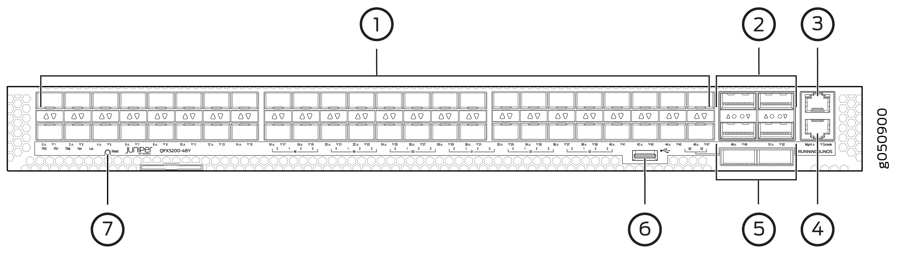
1 — 48 SFP28 ports | 5 — 2 QSFP28 ports |
2 — 4 QSFP28 ports | 6 — USB port |
3 — RJ45 management port | 7 — System status LEDs |
4 — RJ45 console |
Figure 4 describes the connections and components of the QFX5200-48Y management panel.
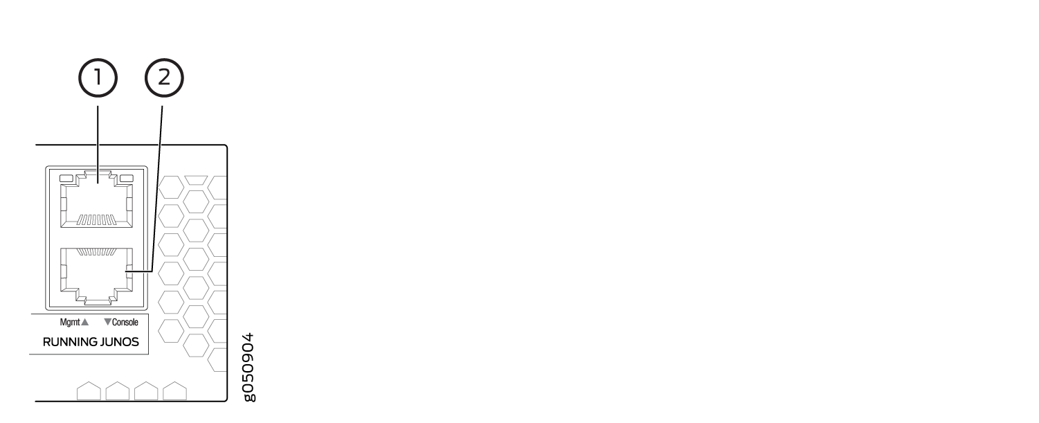
1 — em0–RJ-45 (1000 BASE-T) management Ethernet port (Mgmt) | 2 — RJ-45 console port (Console) |
QFX5200-48Y Management Port LEDs
The management port and console port on a QFX5200-48Y have two LEDs that indicate link status and link activity. The management port is labeled Mgmt for 10/100/1000 BASE-T connections. The left LED indicates status; the right LED indicates link/activity.
Table 3 describes the management port LEDs.
|
LED |
Color |
State |
Description |
|---|---|---|---|
|
Link/Activity |
Unlit |
Off |
No link is established, there is a fault, or the link is down. |
|
Green |
On steadily |
A link is established, but there is no link activity. |
|
|
Blinking or flickering |
A link is established, and there is link activity. |
||
|
Status |
Unlit |
Off |
The link is down. |
|
Green |
On steadily |
The link is up. |
|
LED |
Color |
State |
Description |
|---|---|---|---|
|
Status |
Unlit |
Off |
The console is off. |
|
Green |
On steadily |
The console is on. |
QFX5200 Chassis Status LEDs
The QFX5200 has a series of LEDs that indicate system status. The QFX5200-32C and QFX5200-32C-L have four chassis status LEDs on the management panel; the QFX5200-48Y has five chassis status LEDs on the port panel.
This topic includes:
QFX5200-32C and QFX5200-32C-L Chassis Status LEDs
The QFX5200-32C and QFX5200-32C-L have four status LEDs on the FRU side of the chassis, next to the management ports (see Figure 5).
1 — Status LEDs | 4 — USB port |
2 — em0–RJ-45 (10/100/1000 BASE-T) management Ethernet port (C0) | 5 — em1–SFP management Ethernet port (C1) Cage (socket for either 10/100/1000 Base-T RJ45 SFP or 1GbE fiber SFP) |
3 — RJ-45 console port (CON) ) |
Table 5 describes
the chassis status LEDs on a QFX5200-32C and QFX5200-32C-L, their
colors and states, and the status they indicate. You can view the
colors of the three LEDs remotely through the CLI by issuing the operational
mode command show chassis lcd.
|
Name |
Color |
State |
Description |
|---|---|---|---|
|
ALM–Alarm or beacon |
Unlit |
Off |
The switch is halted or there is no alarm. |
|
Red |
On steadily |
A major hardware fault has occurred, such as a temperature alarm or power failure, and the switch has halted. Power off the QFX5200-32C or QFX5200-32C-L by setting the AC power source outlet to the OFF (O) position, or unplugging the AC power cords. Correct any voltage or site temperature issues, and allow the switch to cool down. Power on the QFX5200-32C and QFX5200-32C-L.Monitor the power supply and fan LEDs to help determine where the error is occurring. |
|
|
Amber |
On steadily |
A minor alarm has occurred, such as a software error. Power off the QFX5200 or QFX5200-32C-L by setting the AC power source outlet to the OFF (O) position, or unplugging the AC power cords. Power on the QFX5200-32C or QFX5200-32C-L and monitor the status LEDs to ensure that Junos OS boots properly. |
|
|
SYS–System |
Unlit |
Off |
The switch is powered off or halted. |
|
Green |
On steadily |
Junos OS for QFX Series is loaded on the switch. |
|
|
MST–Primary RE in a QFX5200-32C Virtual Chassis |
Unlit |
Off |
The switch is standalone. |
|
Green |
On steadily |
The switch is operating as the primary RE in a QFX5200-32C Virtual Chassis. |
|
|
ID–Identification |
Unlit |
Off |
The beacon feature is not enabled on the switch. This feature
is enabled using the |
|
Blue |
Blinking |
The beacon feature is enabled on the switch. This feature is
enabled using the |
QFX5200-48Y Chassis Status LEDs
The QFX5200-48Y switch has five status LEDs on the port side of the chassis, (see Figure 6.)
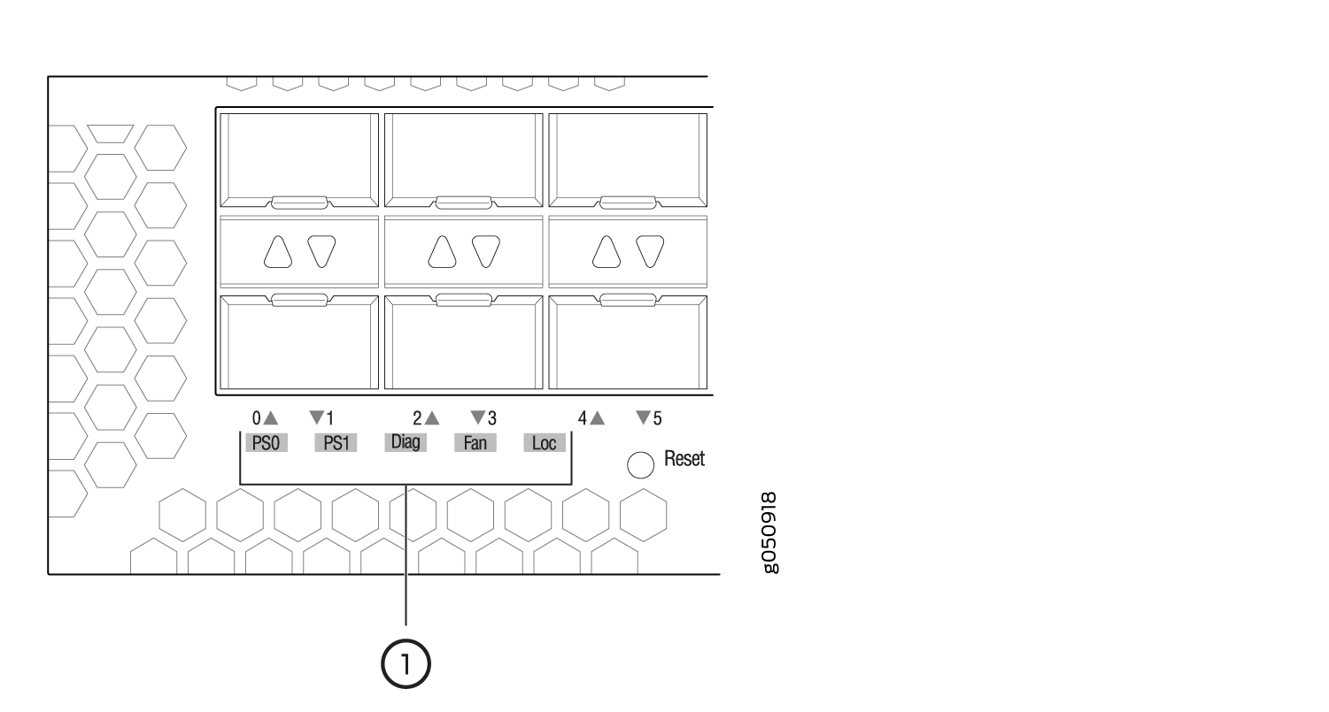
1 — Chassis status LEDs |
Table 6 describes the chassis status LEDs on a QFX5200-48Y, their colors and states, and the status they indicate.
|
Name |
Color |
State |
Description |
|---|---|---|---|
|
PS1 (Power Supply Status) |
Unlit |
Off |
Power supply not present. |
|
Green |
On steadily |
Power supply is working correctly. |
|
|
Amber |
On steadily |
Power supply is faulty |
|
|
PS2 (Power Supply Status) |
Unlit |
Off |
Power supply not present. |
|
Green |
On steadily |
Power supply is working correctly. |
|
|
Amber |
On steadily |
Power supply present but faulty. |
|
|
Diag (Diagnostic) |
Green |
Always in Green |
This LED is always on, with green. You can ignore this. |
|
FAN |
Unlit |
Off |
The switch is powered off. |
|
Green |
On steadily |
Fan operating normally. |
|
|
Amber |
On steadily |
Fan present but faulty. |
|
|
LOC |
Unlit |
Off |
Not a switch to trace its location. |
|
Amber |
Flashing |
Flashing by remote management command. Assists the technician in finding the right device for service in the rack. |