
ON THIS PAGE
Fast Track to Rack Installation and Power
This procedure guides you through the simplest steps to install your QFX5140 in a rack and connect it to power.

Install the QFX5140 in a Rack
You can install the Juniper Networks® QFX5140 in a four-post threaded-hole rack or a four-post square-holed rack. We’ll walk you through the steps to install an AC-powered device in a four-post square-holed rack for a QFX5140 switch.
Ensure that you have the following tools and parts available:
-
An electrostatic discharge (ESD) grounding strap (provided)
-
A pair of front-mounting and rear-floating rails (provided with the rack-mount kit [RMK])
These mounting rails attach to the front and rear rack posts, respectively.
-
A pair of chassis brackets (provided with the RMK)
You must attach these brackets to the device if the brackets are not preinstalled.
Juniper provides the four-post rack mount kit JNP-4P-TL-1RU-RMK with the QFX5140. If the four-post kit is lost or damaged, you can order a replacement.
-
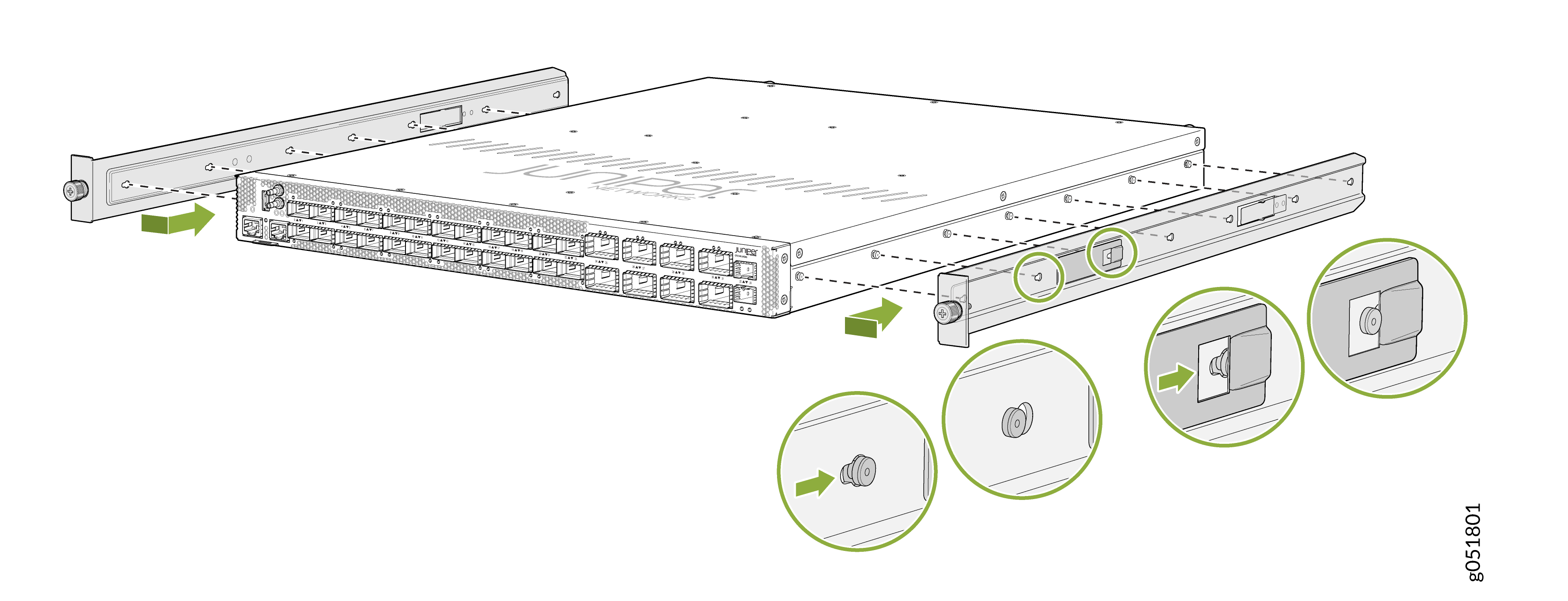
Attach the chassis brackets to the chassis by aligning the keyholes on the
chassis brackets with the shoulder screws on the chassis. Slide the chassis
brackets toward the rear of the chassis.
Figure 1: Install the Chassis Brackets
-
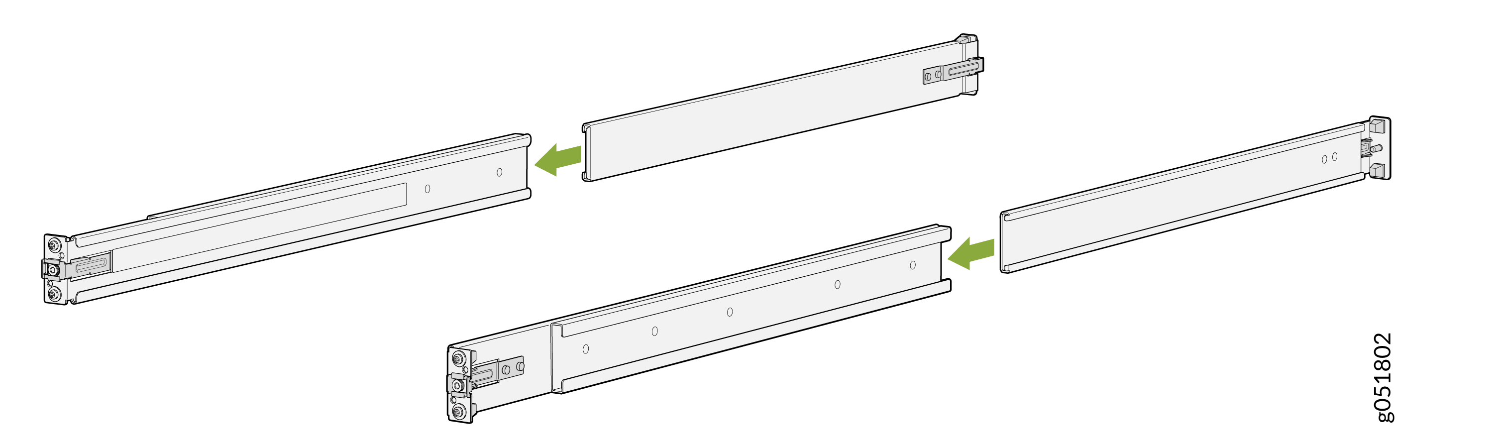
Assemble the mounting rails by sliding the rear-floating rails into the
respective front-mounting rails.
Figure 2: Assemble the Mounting Rails
-
Install the mounting rails on the four-post rack:
-
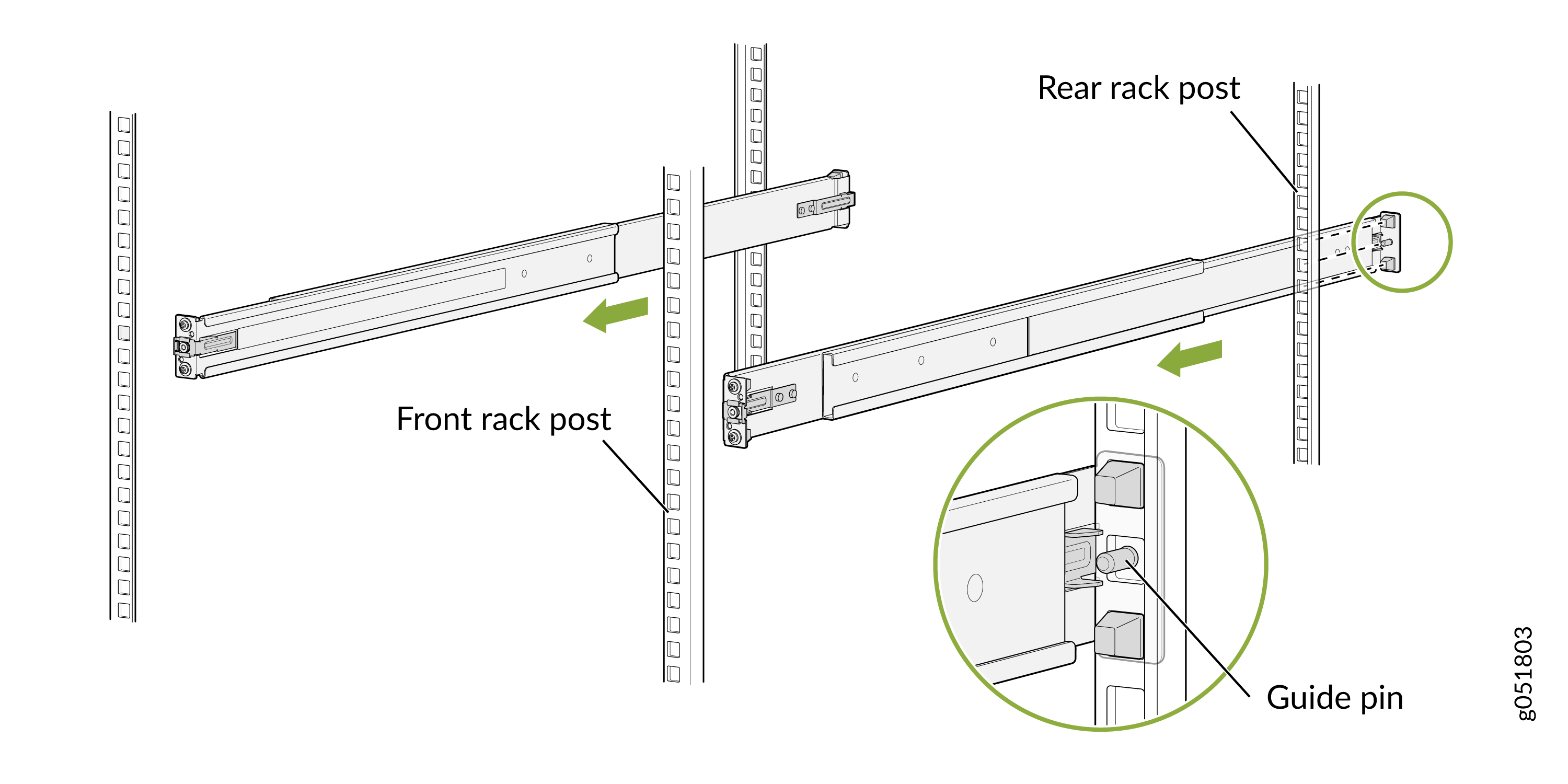
Use the guide pin to align the guide blocks of the rear-floating
rails with the corresponding rear post holes. Pull the rear-floating
rails toward the front of the rack to lock the rails in place. You
will hear a distinct click sound when the latch locks into the
corresponding rack holes.
Figure 3: Secure Rear-Floating Rails
-
Align the guide blocks of the front-mounting rails with the front
post holes. Push the front-mounting rails toward the rear of the
rack to lock the rails in place. You will hear a distinct click
sound when the latch locks into the corresponding rack holes.
Figure 4: Secure Front-Mounting Rails
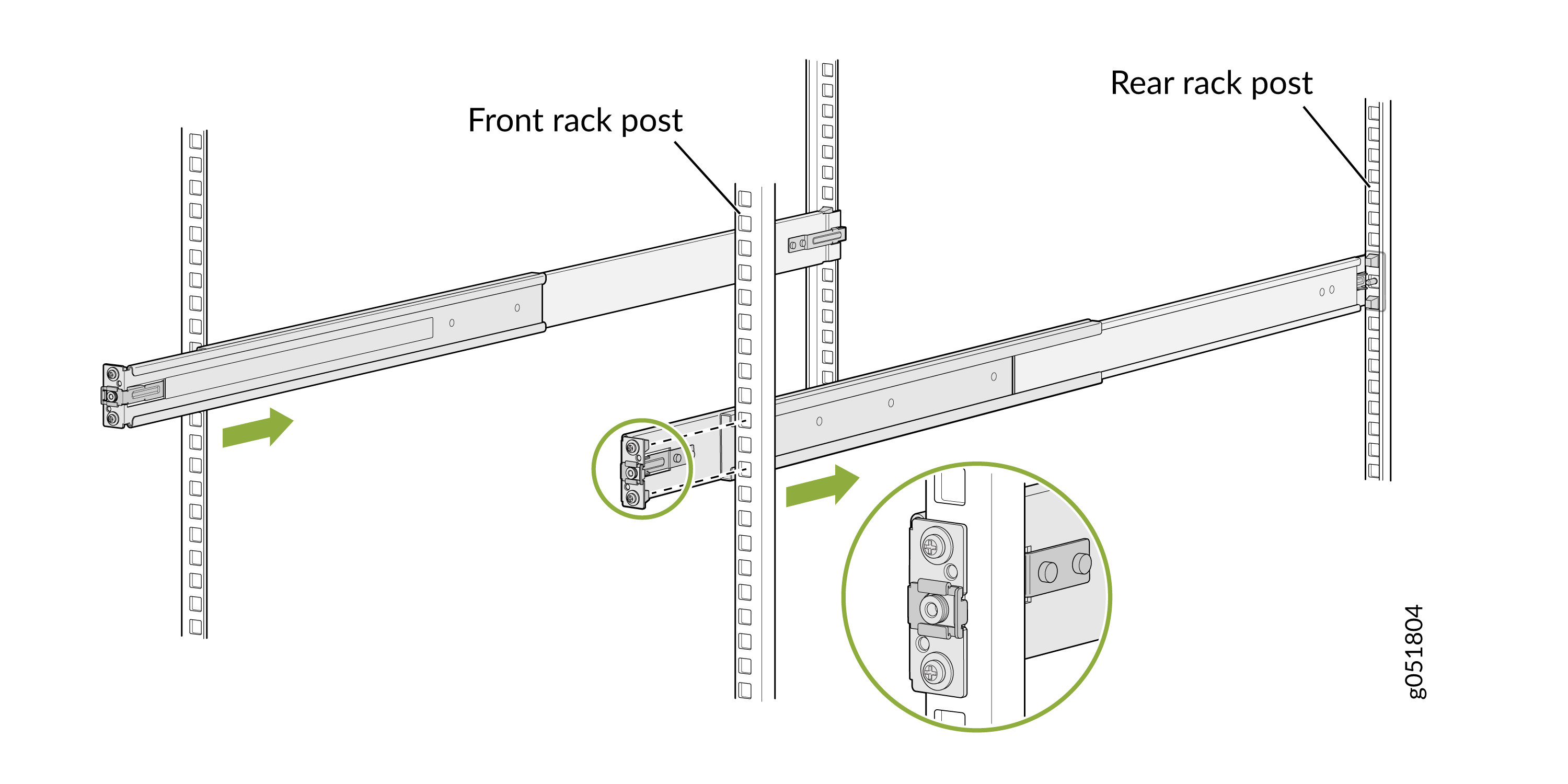 Figure 5: Both Mounting Rails Installed and Secured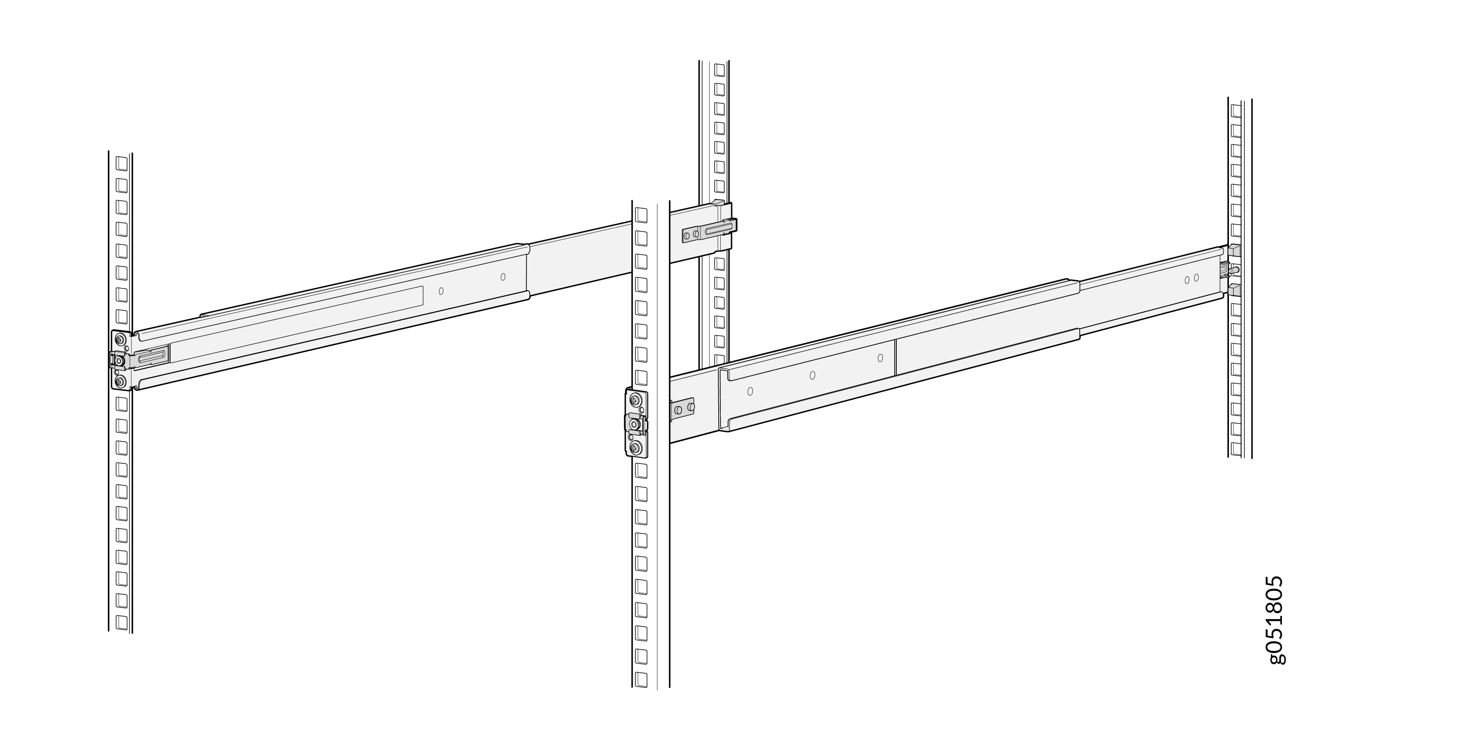
-
Use the guide pin to align the guide blocks of the rear-floating
rails with the corresponding rear post holes. Pull the rear-floating
rails toward the front of the rack to lock the rails in place. You
will hear a distinct click sound when the latch locks into the
corresponding rack holes.
-
Lift the device and position it in the rack, aligning the chassis brackets
with the mounting rails. Slide the device all the way into the channels of
the mounting rails.
Note:
In an airflow out (AFO) configuration, the chassis is installed with its front panel facing the front of the rack.
Figure 6: Slide the QFX5140 into the Rack (for AFO configuration)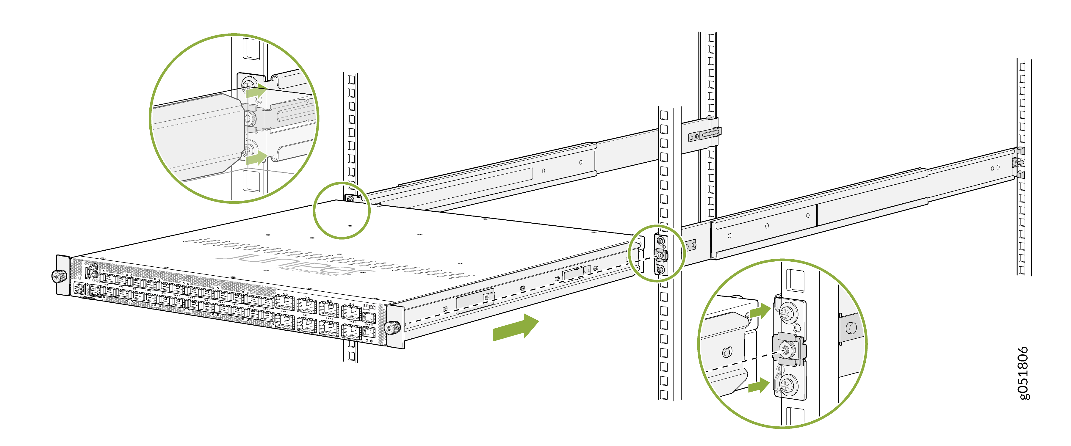 Note:
Note:In an airflow in (AFI) configuration, the chassis is installed with its rear panel facing the front of the rack and its front panel facing the rear. This orientation may appear unusual, but it is required for proper airflow in an AFI configuration.
Figure 7: Slide the QFX5140 in the Rack (for AFI Configuration)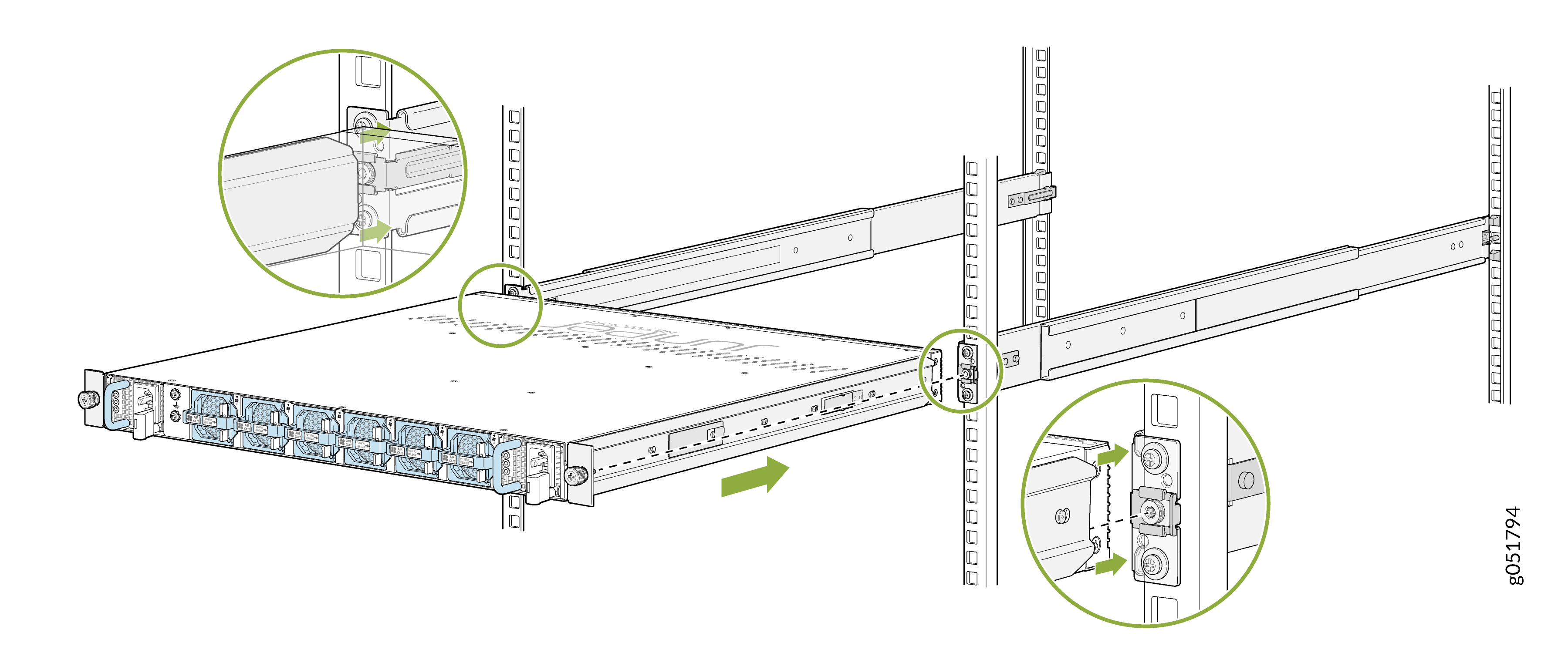
-
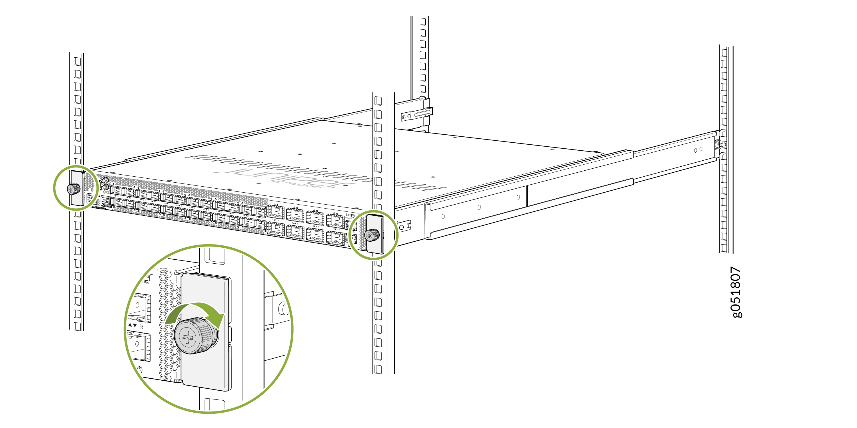
Tighten the two thumbscrews (in a clockwise direction) to secure the
device.
Figure 8: Tighten the Thumbscrews
Connect to Power
To connect the QFX5140 to AC power, you must perform the following tasks:
Ground the QFX5140
To meet safety and electromagnetic interference (EMI) requirements and to ensure proper operation, you must connect the QFX5140 to an earth ground before you connect it to power.
Before you connect the earth ground and the protective earthing terminal of the device, ensure that a licensed electrician attaches an appropriate grounding terminal to the grounding cable. Using a grounding cable with an incorrectly attached terminal can damage the device.
Before connecting the device to an earth ground, ensure that you have the following parts and tools:
-
An electrostatic discharge (ESD) grounding strap.
-
A grounding cable for your device—The grounding cable must be 6 AWG (4.11 mm²) stranded wire and rated 90 °C or according to the local electrical code.
-
A grounding 2-hole terminal lug for your grounding cable—The grounding terminal lug attaches to the chassis grounding point.
-
A Phillips (+) screwdriver, number 2 to tighten the screw.
To ground the QFX5140:
Ensure that all grounding surfaces are clean and brought to a bright finish before making the grounding connections.
Connect the grounding cable to a proper earth ground, such as the rack in which you mount the device.
Using the Phillips screwdriver, remove the screws from the chassis grounding point.
Secure the terminal lug attached to the other end of the grounding cable to the chassis grounding point by using the screws that you removed from the chassis grounding point.
Figure 9: Grounding Point on the QFX5140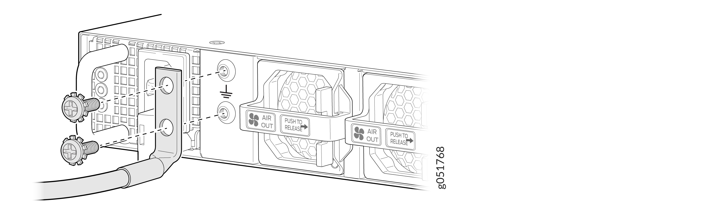
Verify that the grounding cable does not touch or block access to the device components. Make sure that the cable does not trail across the floor where people could trip over it.
Note:Ensure that the device is permanently connected to ground during its operation.
Connect the Power Cord and Power On the QFX5140
Do not mix AC and DC power supply units (PSUs) in the same chassis.
Before you begin to connect the device to AC power:
-
Ensure that you have connected the chassis to an earth ground.
-
Ensure that you have a power cord appropriate for your geographical location available to connect the device to AC power.
-
Ensure that you have taken the necessary precautions to prevent electrostatic discharge (ESD) damage.
-
Ensure that you have an ESD grounding strap.
-
If not already installed, install the PSUs in the device.
To connect the power cord and power on the device:
Align the AC power cable connector with the PSU inlet.
Insert the AC power cable.
.
Push the connector firmly into the PSU inlet until fully seated.
Figure 10: Connect Power Cord to the QFX5140 AC PSU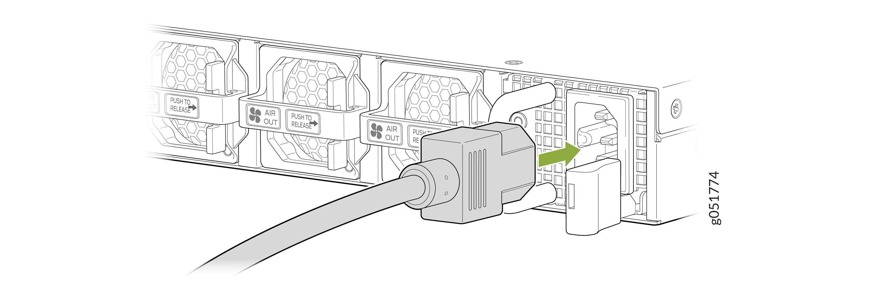
If the AC power source outlet has a power switch, set it to the off (O) position.
Insert the power cord plug into the AC power source outlet.
Note:Connect each PSU to a dedicated AC power feed and a dedicated external circuit breaker. We recommend that you use a minimum of 16 A (250 VAC), or as permitted by the local code.
If the AC power source outlet has a power switch, set it to the on (|) position.