
ON THIS PAGE
QFX5140 Cooling System
The cooling systems on the QFX5140 work together to keep the temperature of all internal components within the acceptable range. The cooling system components in the QFX5140 include fan modules and power supply cooling systems.
The QFX5140 Switch includes six fan modules that support N+1 redundancy at rotor level. The QFX5140 cooling system consists of six hot‑swappable fan modules installed in the rear FRU panel of the chassis. Each fan modules houses two 40mm x 40mm counter rotating rotors. The switch supports both airflow‑in (FRU‑to‑port) and airflow‑out (port‑to‑FRU) configurations.
The fan modules in the QFX5140 are hot-insertable and hot-removable field-replaceable units (FRUs). You can install the fans in the fan module slots on the rear of the chassis. The fans are numbered 0 through 5 starting from the fan module closest to the grounding points on the chassis.
Airflow
The QFX5140 comes with models that support a front-to-back (AIR OUT) and a back-to-front (AIR IN) cooling system.
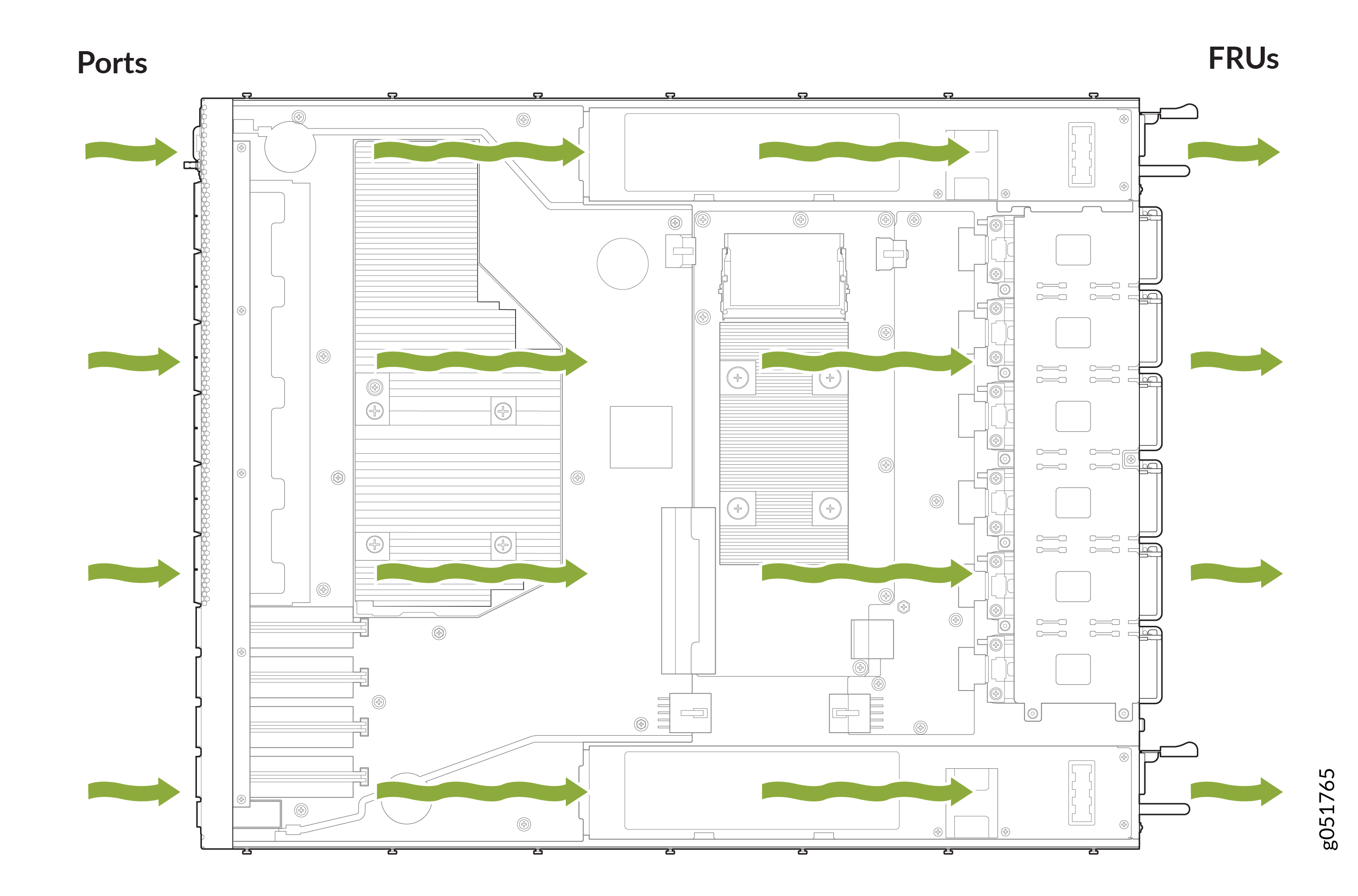
In a front-to-back cooling system, cool air enters through the front vents. The fan modules then exhaust hot air through the rear of the chassis. Figure 1 shows the airflow through the QFX5140 chassis that uses a front-to-back cooling system.
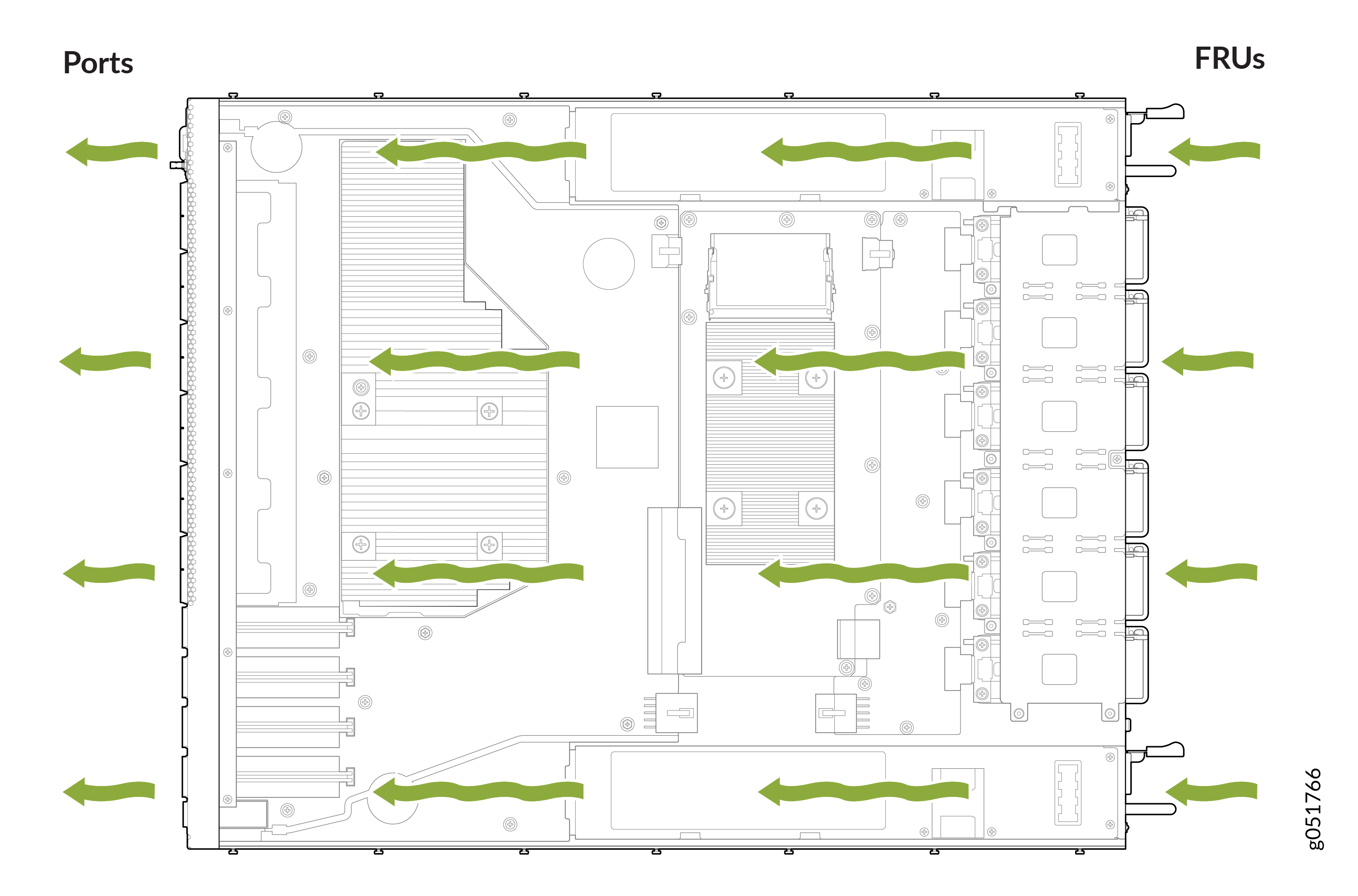
In the QFX5140 switch models that have back-to-front airflow, the air intake to cool the chassis is through the vents on the rear panel and hot air exhausts through the vents on the front panel of the switch. a
Figure 2 shows the airflow through the QFX5140 chassis that uses a back-to-front cooling system.
Temperature sensors in the chassis monitor the temperature within the chassis. Under normal operating conditions, the fan modules operate at a moderate speed. If a fan fails, the speed of the remaining fans is automatically adjusted to keep the temperature within the acceptable range. If the ambient temperature rises above a threshold, similarly, fan speeds are automatically adjusted to maintain the acceptable temperature range. If the ambient temperature exceeds the specified threshold and the system cannot adequately cool down, the Routing Engine shuts down the router by disabling output power from each power supply.
If one of the fans in a fan module fails, the QFX5140 Switch will raise an alarm for the fan tray slot with the failed fan. The router will however continue to operate without issues. You can leave the fan module with the failed fan in the chassis until a replacement fan module is available. When a replacement fan module is available and if the router is online, you can replace one fan module at a time. During replacement, the router will raise a major alarm for the missing fan module and continue to operate for a certain period after which the router will shut down. To avoid the router from shutting down, you must replace the fan module within this time.
If you remove more than one fan module while the router is online, the router will shut down within 30 seconds.
To avoid disturbing the airflow and cooling, don't operate the router when a fan module is removed.
Power Supply Cooling System
The power supply units (PSUs) are self-cooling with inbuilt fans. The PSUs are located at the rear of the QFX5140. A baffle directs airflow through an isolated air channel from the front of the chassis specifically to help the PSUs maintain thermal requirements.
QFX5140-FANAO
Figure 3 shows the location of the fan modules on the back panel of the QFX5140 switch.
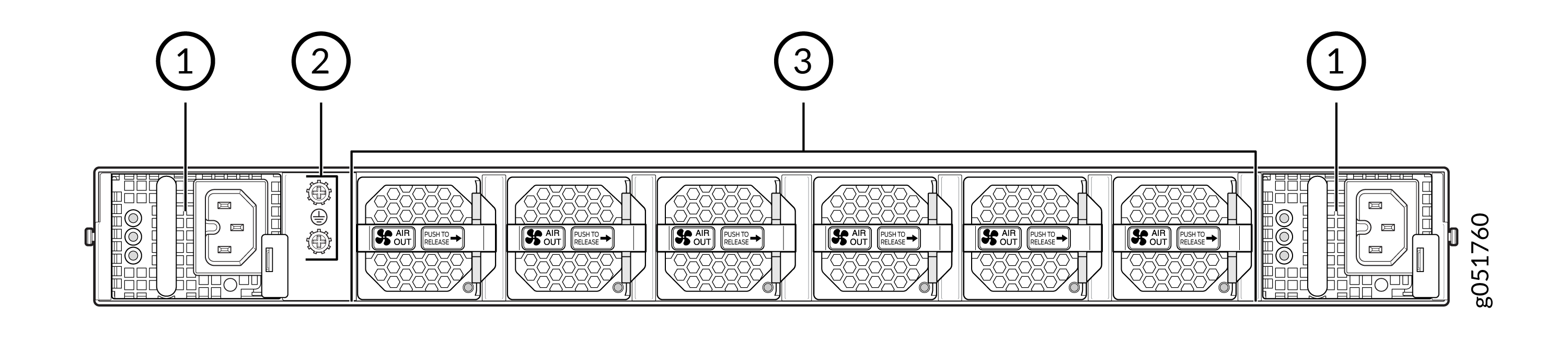
1 — AC Power Supply Unit | 3 — Fan Modules (6 units) |
2 — Grounding Point |
The AIR OUT label and the Juniper Gold handle indicates front-to-back airflow.
QFX5140-FANAO Specifications
QFX5140-FANAO Specifications shows the physical specifications of the fan module.| Specification | Value |
|---|---|
|
Height |
1.57 in. (4 cm) |
|
Width |
1.57 in. (4 cm) |
|
Depth |
2.20 in. (5.6 cm) |
|
Weight |
0.21 lbs (97 g) |
|
Airflow |
AFO |
QFX5140-FANAO LED
You can check the status of each fan module through the show chassis
fan or show chassis environment commands. You can
also check the status by looking at the LED of each fan module. The LED is
positioned beneath the handle of the fan module, on the right side.
Figure 4 shows the location of the LED on the fan module.
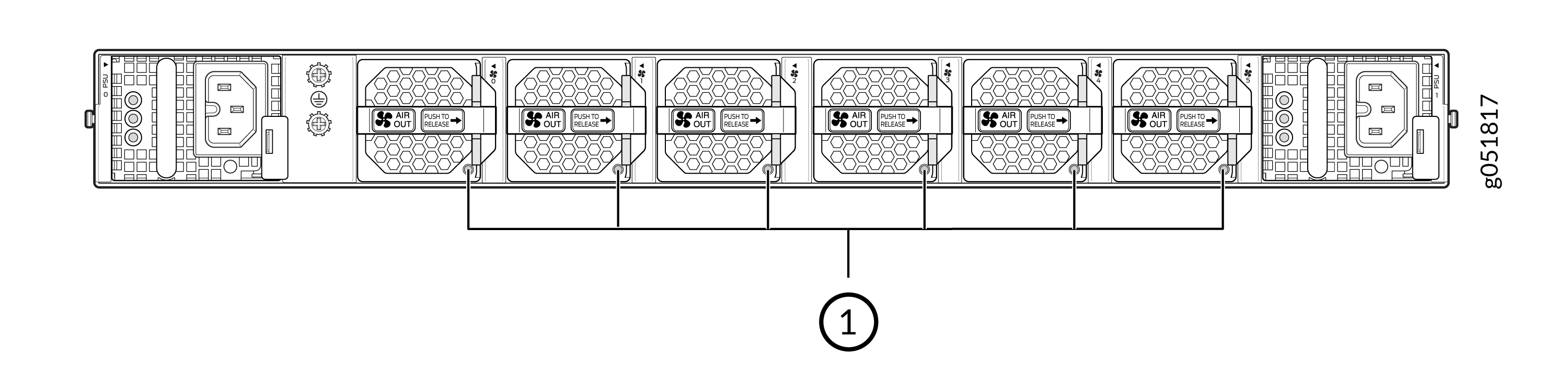
Table 2 describes the QFX5140-FANAO LED fan module status LED.
| Callout | LED Color | State | Description |
|---|---|---|---|
| `1 | Green | On Steadily | Fan functioning normally |
| Red | On Steadily | Fan not detected or fan not functioning |
You can also get information about the fan modules using the show chassis
fan command. Here is an example of the CLI output:
QFX5140 with Six Fan Modules
user@device> show chassis fan
Item                      Status      Measurement
Fan Tray 0 Fan 1          OK           13650 RPM
Fan Tray 0 Fan 2          OK           12300 RPM
Fan Tray 1 Fan 1          OK           13800 RPM
Fan Tray 1 Fan 2          OK           12300 RPM
Fan Tray 2 Fan 1          OK           13650 RPM
Fan Tray 2 Fan 2          OK           12300 RPM
Fan Tray 3 Fan 1          OK           13650 RPM
Fan Tray 3 Fan 2          OK           12150 RPM
Fan Tray 4 Fan 1          OK           13800 RPM
Fan Tray 4 Fan 2          OK           12300 RPM
Fan Tray 5 Fan 1          OK           13650 RPM
Fan Tray 5 Fan 2          OK           12450 RPM