Maintain the QFX5120 Cooling System
Remove a Fan Module from a QFX5120 Switch
Before you remove a fan module in from the switch, ensure that you have the following parts and tools available:
-
Number 2 Phillips (+) screwdriver—not provided
-
An antistatic bag or an antistatic mat—not provided
-
A replacement fan module
We ship QFX5120-32C switches with 5+1 redundant fans preinstalled in the rear panel. We ship QFX5120-48T, QFX5120-48Y, and QFX5120-48YM switches with 4+1 redundant fans preinstalled in the rear panel. The fan modules are hot-removable and hot-insertable field-replaceable units (FRUs) installed in the rear panel of the switch: You can remove and replace them without powering off the switch or disrupting switch functions.
-
Grasp the handle on the fan module and pull it firmly
to slide the fan module out of the chassis. Figure 1 shows how to remove
a fan module from a QFX5120-32C switch.
Figure 3 shows how to remove
a fan module from a QFX5120-48T or QFX5120-48Y switch. Figure 2 shows how to remove
a fan module from a QFX5120-48YM switch.
Figure 1: Remove a Fan Module from a QFX5120-32C Switch
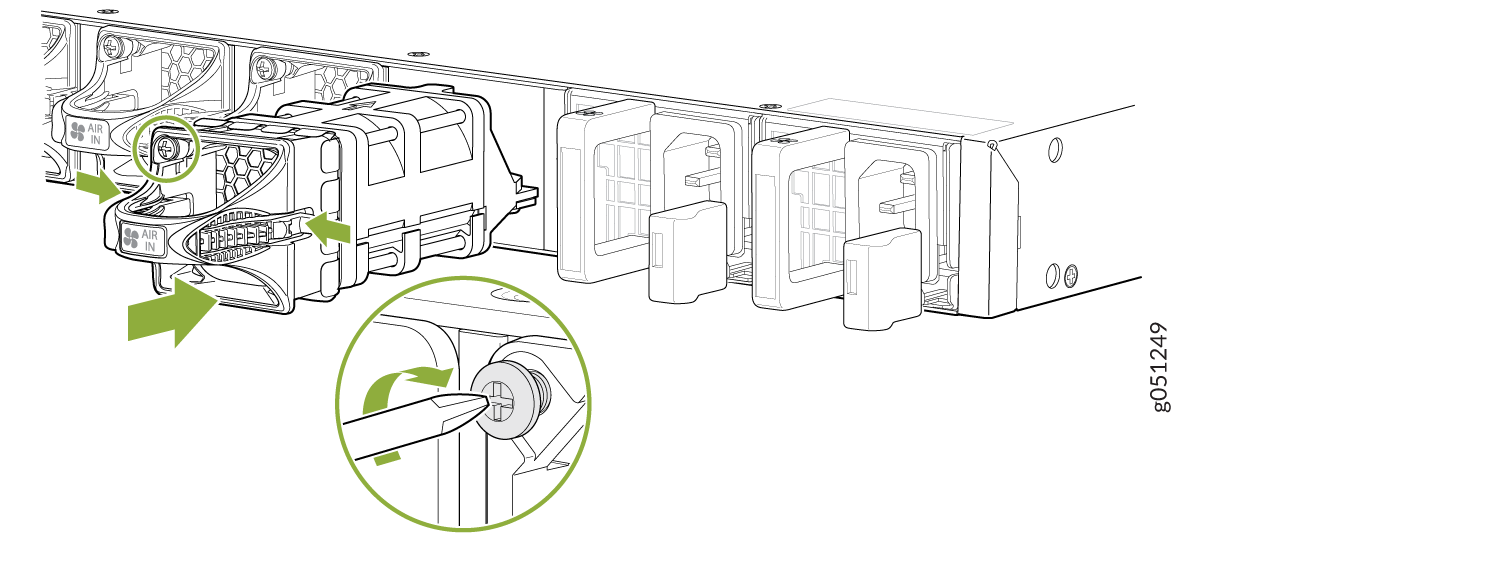
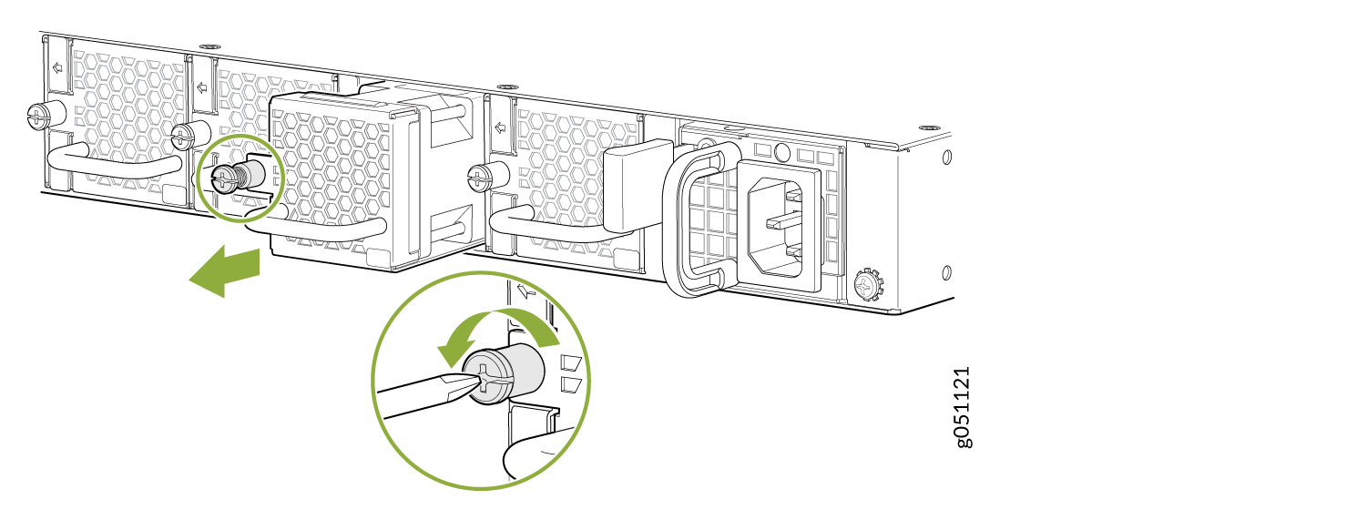 Figure 2: Remove a Fan Module from a QFX5120-48T or QFX5120-48Y Switch
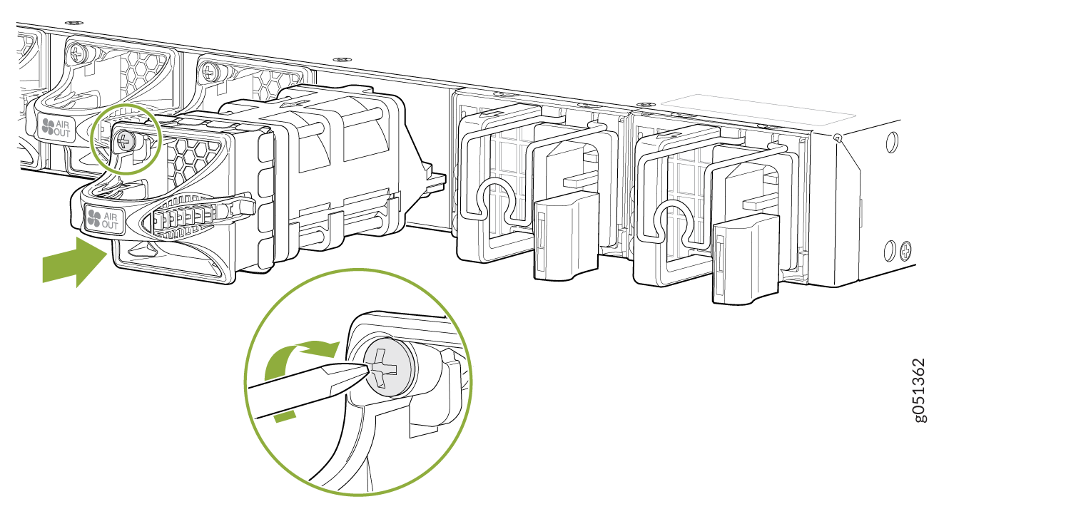
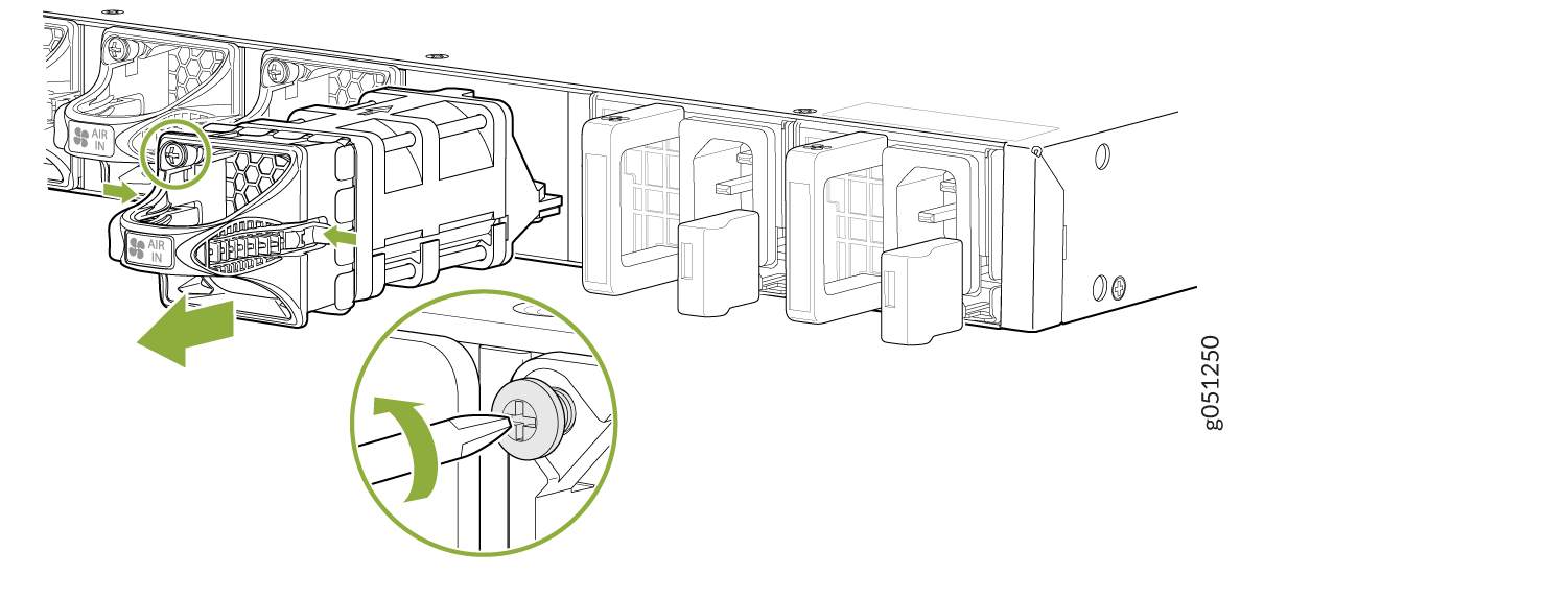 Figure 3: Remove a Fan Module from a QFX5120-48YM Switch
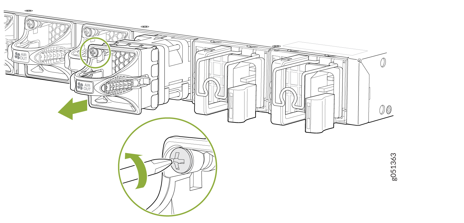
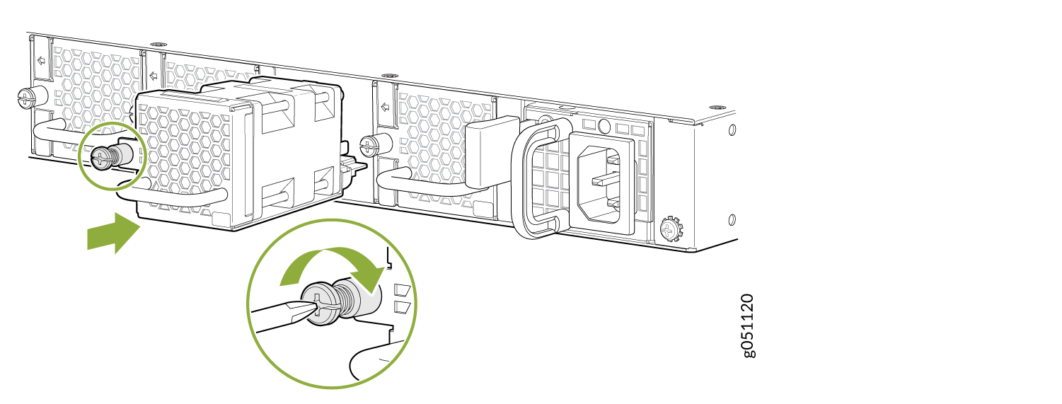
Install a Fan Module in a QFX5120 Switch
Before you install a fan module in the switch:
-
Ensure that you understand how to prevent electrostatic discharge (ESD) damage (see Prevention of Electrostatic Discharge Damage).
-
Ensure that you have the following parts and tools available:
-
ESD grounding strap—not provided
-
Number 2 Phillips (+) screwdriver—not provided
-
We ship QFX5120-32C switches with 5+1 redundant fans preinstalled in the rear panel. We ship QFX5120-48T, QFX5120-48Y, and QFX5120-48YM switches with 4+1 redundant fans preinstalled in the rear panel. The fan modules are hot-removable and hot-insertable field-replaceable units (FRUs) installed in the rear panel of the switch: You can remove and replace them without powering off the switch or disrupting switch functions.
Do not mix:
-
Fan modules with different airflow directions in the same chassis.
-
Power supplies with different airflow directions in the same chassis.
-
Fan modules and power supplies with different airflow directions in the same chassis.
If you have a Juniper J-Care service contract, register any addition, change, or upgrade of hardware components at https://www.juniper.net/customers/support/tools/updateinstallbase/. Failure to do so can result in significant delays if you need replacement parts. This note does not apply if you replace existing components with the same type of component.