Connect the QFX5120 to External Devices
Connect a Device to a Network for Out-of-Band Management
Ensure that you have an Ethernet cable that has an RJ-45 connector at either end.
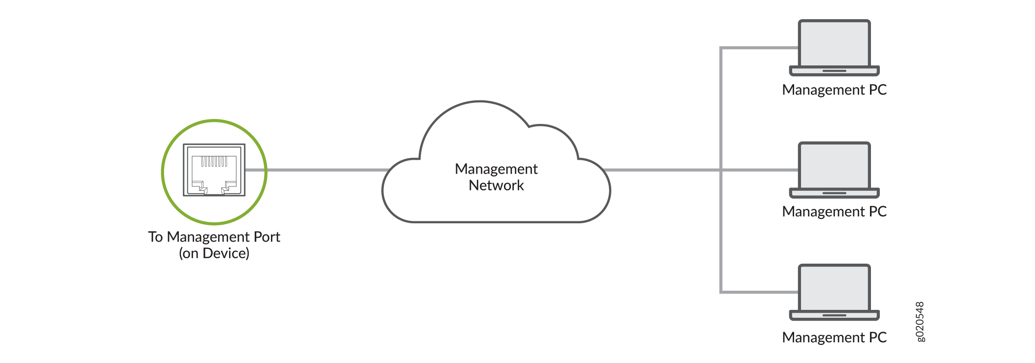
You can monitor and manage a network device, such as a router or a switch, by using a dedicated management channel. Each device has a management port to which you can connect an Ethernet cable with an RJ-45 connector. Use the management port to connect the device to the management device.
To connect a device to a network for out-of-band management:
- Connect one end of the Ethernet cable to the management port on the device.
- Connect the other end of the Ethernet cable to the management device.
Connect a Device to a Management Console Using an RJ‑45 Connector
Ensure that you have an Ethernet cable that has an RJ-45 connector at either end and an RJ-45-to-DB-9 serial port adapter.
- RJ-45 to DB-9 adapter (JNP-CBL-RJ45-DB9)
- RJ-45 to USB-A adapter (JNP-CBL-RJ45-USBA)
- RJ-45 to USB-C adapter (JNP-CBL-RJ45-USBC)
If you want to use RJ-45 to USB-A or RJ-45 to USB-C adapter, you must have X64 (64-Bit) Virtual COM port (VCP) driver installed on your PC. See https://ftdichip.com/drivers/vcp-drivers/ to download the driver.
If your laptop or desktop PC does not have a DB-9 plug connector pin and you want to connect your laptop or desktop PC directly to the device, use a combination of the RJ-45-to-DB-9 socket adapter and a USB-to-DB-9 plug adapter. You must provide the USB-to-DB-9 plug adapter.
You can configure and manage your network devices using a dedicated management channel. Each device has a console port that you can connect to using an Ethernet cable with an RJ-45 connector. Use the console port to connect the device to the console server or management console. The console port accepts a cable that has an RJ-45 connector.
To connect the device to a management console:
- Connect one end of the Ethernet cable to the console port (labeled CON, CONSOLE, or CON1) on the device.
- Connect the other end of the Ethernet cable to the console server (see Figure 3) or management console (see Figure 4).


Connecting 1-PPS and 10-MHz Measurement Devices to the QFX5120 Switch
Before you connect a QFX5120-48T or QFX5120-48YM switch to measurement devices:
Ensure that the measurement equipment is compatible with transistor-transistor logic (TTL) (5.0 V).
Ensure that you have a cable with length up to 3 m.
QFX5120-48T and QFX5120-48YM switches have one 2x1 DIN 1.0/2.3 connector that supports 1-PPS-OUT and 10-MHz-OUT measurement ports, labeled PPS OUT and 10M OUT, on the rear panel of the switch.
To connect the DIN cable to the external measurement device:
- Connect one end of the DIN cable connectors to the 1-PPS-OUT and the 10-MHz-OUT ports, labeled PPS OUT and 10M OUT, on the rear panel of the switch.
- Connect the other end of the DIN cable connectors to the measurement equipment.