QFX5110 Cooling System
QFX5110 Cooling System and Airflow Description
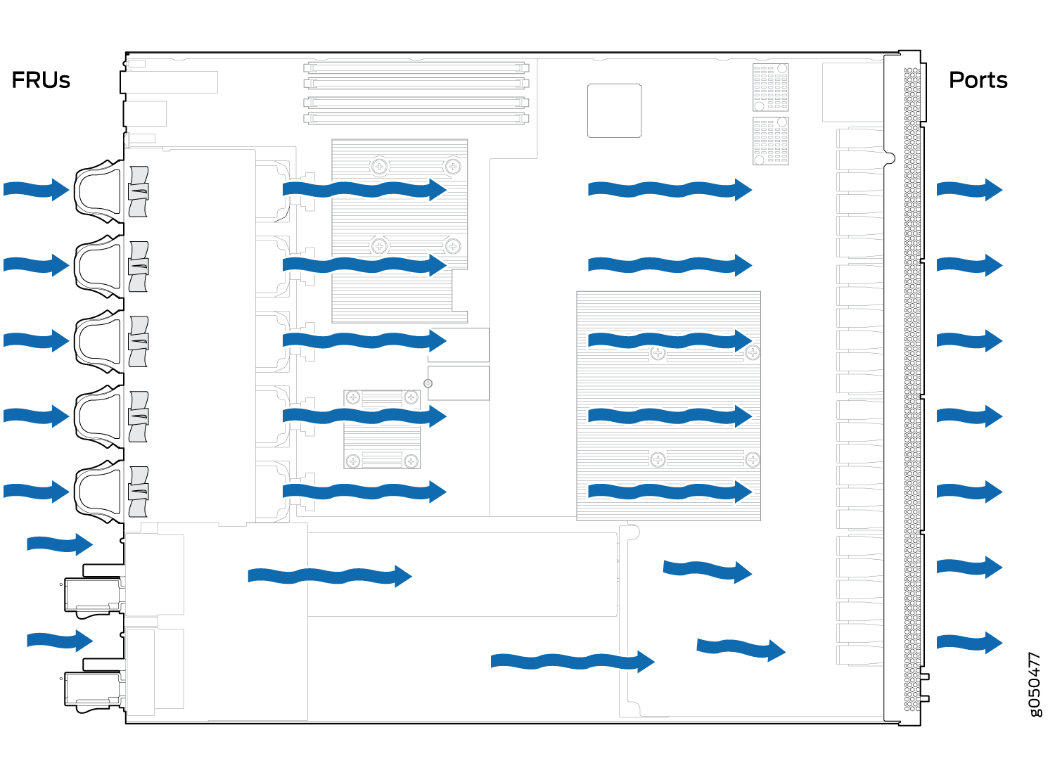
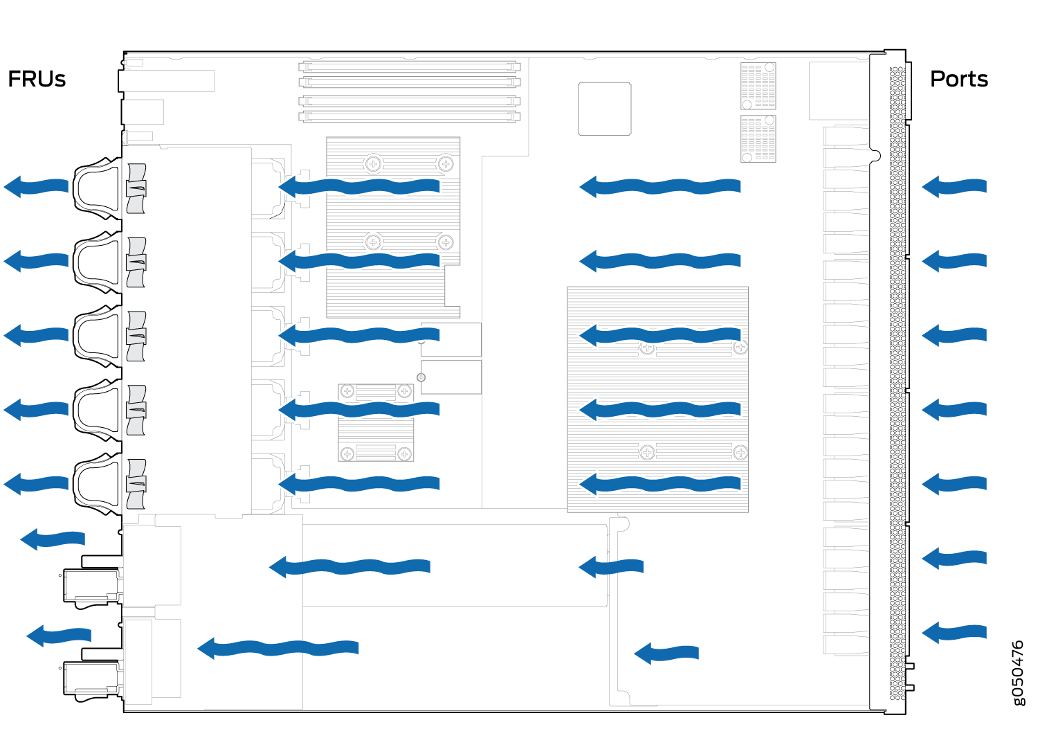
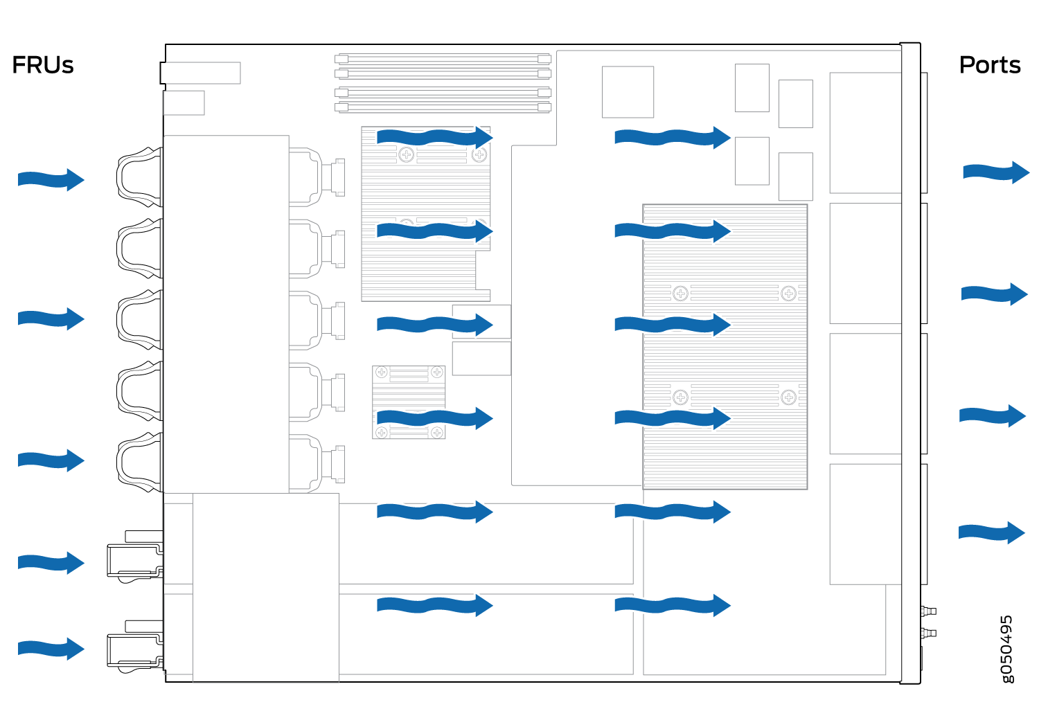
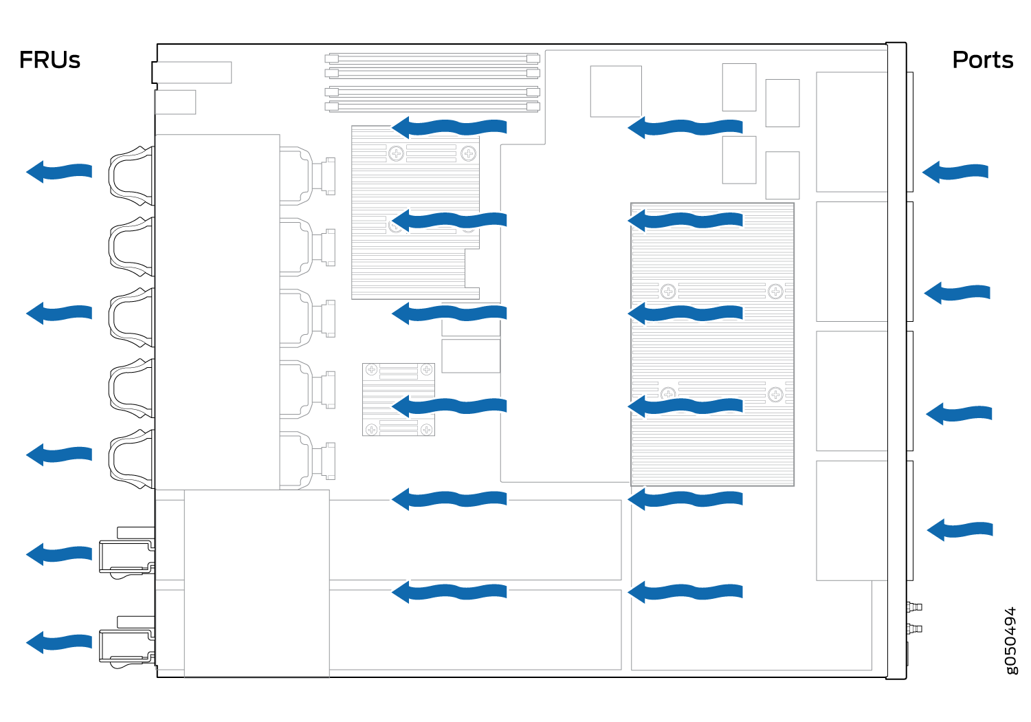
The cooling system in an QFX5110 device consists of five fan modules and a single fan in each power supply. The switch can be set up to work in one of two airflow directions:
-
Airflow In–Air comes into the switch through the vents in the field-replaceable units (FRUs)
-
Airflow Out–Air comes into the switch through the vents in the port panel.
All QFX5110 switches, except the QFX5110-32Q-CHAS, are shipped with five fan modules and two power supplies. Order fans for the QFX5110-32Q-CHAS separately.
Airflow In and Airflow Out fans and power supplies cannot be mixed in the same chassis.
This topic describes:
Fan Modules
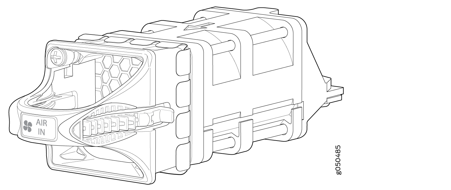
The fan modules in QFX5110 devices are hot-insertable and hot-removable FRUs. These fan modules are designed for one of the two available airflow directions (Airflow In or Airflow Out). The fan modules are also color-coded for the airflow direction. The fan modules are installed in the fan module slots between the management panel and the power supplies.
The QFX5110 fan modules have five fan modules numbered 0 through 4 counting from left to right. Each fan module slot has a fan icon next to it.
Figure 1 shows the fan module.
You remove and replace a fan module from the FRU end of the chassis. The switch continues to operate for a limited period of time (30 seconds) during the replacement of the fan module without thermal shutdown.
All fan modules must be installed for optimal operation of the switch.
The fan modules are available in two product SKUs that have different airflow directions, airflow in and airflow out. Airflow in is indicated on the module by the azure blue color and a label marked AIR IN. Airflow in this version of the fan module bring air into the fans and power supplies and exhaust air through the ports. Likewise, airflow out is indicated by a gold color and a label marked AIR OUT. Airflow out versions of the fan module brings air into the switch through the vents around the ports and exhaust air through the fans and power supplies. Table 1 lists the available fan module product SKUs and the direction of airflow in them.
|
Fan Module |
Airflow Diagram |
Label on the Fan Module |
Color of Fan Module |
Direction of Airflow in the Fan Module |
Power Supplies |
|---|---|---|---|---|---|
|
QFX5110-48S-FANAFI |
AIR IN |
Juniper Azure Blue |
FRU-to-port, that is, air comes in from the end of the switch with the fans; air exhausts from the switch end with ports (also known as back-to-front airflow). |
You must install only power supplies that have AIR IN labels in switches in which the fan modules have AIR IN labels. |
|
|
QFX5110-48S-FANAFO |
AIR OUT |
Juniper Gold |
Port-to-FRU, that is, air comes in through vents on the end with ports; air exhausts out the end with the fans (also known as front-to-back airflow). |
You must install only power supplies that have AIR OUT labels in switches in which the fan modules have AIR OUT labels. |
|
|
QFX5110-32Q-FANAFI |
AIR IN |
Juniper Azure Blue |
FRU-to-port, that is, air comes in from the end of the switch with the fans; air exhausts from the switch end with ports (also known as back-to-front airflow). |
You must install only power supplies that have AIR IN labels in switches in which the fan modules have AIR IN labels. |
|
|
QFX5110-32Q-FANAFO |
AIR OUT |
Juniper Gold |
Port-to-FRU, that is, air comes in through vents on the end with ports; air exhausts out the end with the fans (also known as front-to-back airflow). |
You must install only power supplies that have AIR OUT labels in switches in which the fan modules have AIR OUT labels. |
In data center deployments, position the switch in such a manner that the AIR IN labels on switch components are next to the cold aisle, and AIR OUT labels on switch components are next to the hot aisle. See Figure 2 through Figure 5.
Do Not Install Components with Different Airflow or Wattage in the Switch
Do not mix power supplies with different airflow. If the power supplies are color-coded, ensure they are either all azure blue for airflow in models or all gold for airflow out models. If the power supplies are not color-coded but have a label, ensure that the chassis is either using all airflow in (AFI ) or all airflow out (AFO). Likewise, ensure that all fan modules have the same airflow and match the airflow of the power supplies. Fan modules are also either color-coded azure blue for airflow in or gold for airflow out. If the fan module has a label instead of being color-coded, ensure that labels (AIR IN and AIR OUT) are not mixed. If the fan modules have AIR IN labels, the power supplies must also have AIR IN labels; if the fan modules have AIR OUT labels, the power supplies must also have AIR OUT labels.
Mixing components with different airflows in the same chassis hampers the performance of the cooling system of the switch and leads to overheating of the chassis.
The system raises an alarm if a fan module fails or if the ambient temperature inside the chassis rises above the acceptable range. If the temperature inside the chassis rises above the threshold temperature, the system shuts down automatically.
Do not mix fan modules with different wattage. Only use the replacement fan modules that are designed for use with your product number. See Table 1 for the correct part number for your QFX5110.
Do not mix AC and DC power supplies in the same chassis.
However, if you need to convert a QFX5110 to have a different airflow, you can change the airflow pattern. To convert an AIR IN product SKU to an AIR OUT product SKU or an AIR OUT product SKU to a AIR IN product SKU, you must replace all of the fans and power supplies at one time to use the new direction. The system raises an alarm when the system is converted, which is normal.
QFX5110 Fan Module LED
Figure 6 shows the location of the LED next to the fan module.
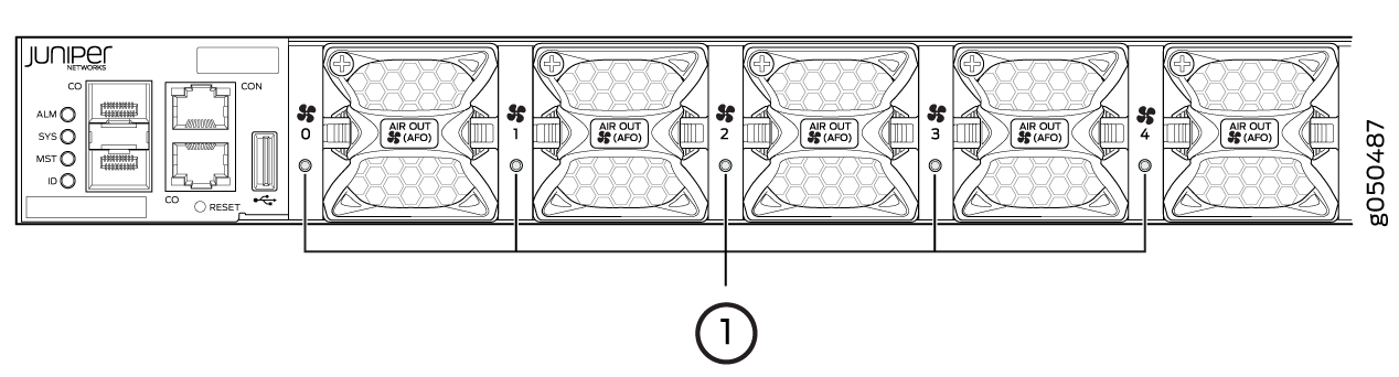
1 — Fan LED |
Table 2 describes the function of the fan tray LED.
|
Name |
Color |
State |
Description |
|---|---|---|---|
|
Fan |
Green |
On steadily |
The fan module is operating normally. The system has verified that the module is engaged, that the airflow is in the correct direction, and that the fan is operating correctly. |
|
Amber |
Blinking |
An error has been detected in the fan module. Replace the fan module as soon as possible. Either the fan has failed or it is seated incorrectly. To maintain proper airflow through the chassis, leave the fan module installed in the chassis until you are ready to replace it. |
Under normal operating conditions, the fan modules operate at a moderate speed. Temperature sensors in the chassis monitor the temperature within the chassis.
The system raises an alarm if a fan module fails or if the ambient temperature inside the chassis rises above the acceptable range. If the temperature inside the chassis rises above the threshold temperature, the system shuts down automatically.