QFX10002 Management Panel
QFX10002 Management Panel
The QFX10002 management panel is found next to the ports as shown in Figure 1 through Figure 3. See Figure 4 and Figure 5 for management panel detail.
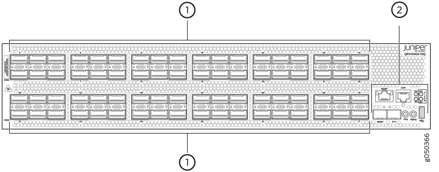
1 — Port panel | 2 — Management panel |
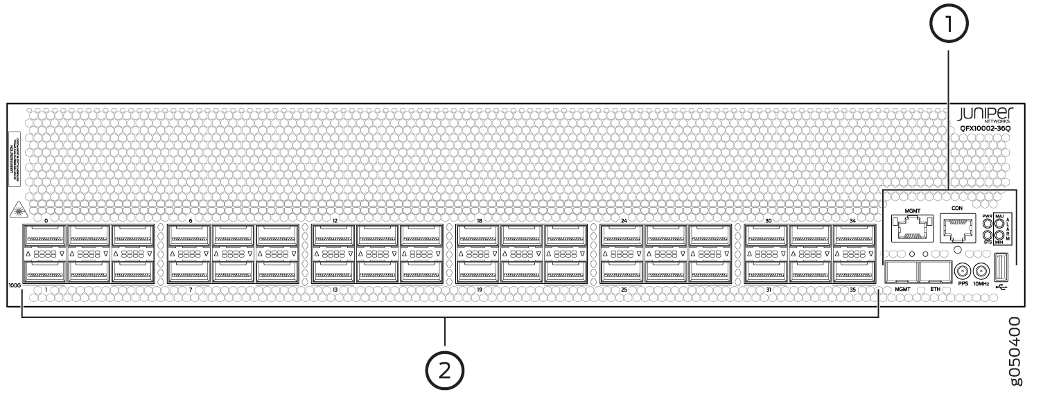
1 — Management panel | 2 — Port panel with QSFP+ network interface or uplink ports (36) |
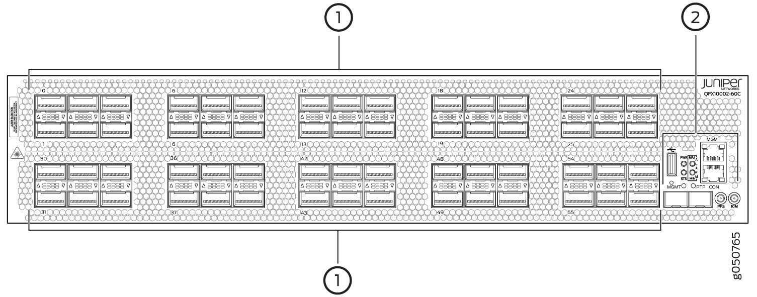
1 — Port panel | 2 — Management panel |
1 — em0–RJ-45 (1000BASE-T) management Ethernet port (MGMT). | 6 — PTP Ethernet–SFP (1000BASE-T) port (ETH) |
2 — RJ-45 console port (CON) to support RS-232 serial ports. The LED below the port indicates status and link. | 7 — 10 Hz pulses-per-second (PPS) SubMiniature B (SMB) connector for input and output measuring of the timing drift to and from a grandmaster clock |
3 — Reset button. Press and hold 5 seconds to reset the hardware. Clock functions and FPGA status registers are not reset. | 8 — 10 MHz SMB timing connector (10MHz) |
4 — Status LEDs–Power (PWR), status (STA), major alarm (MJR), and minor alarm (MIN). | 9 — USB port |
5 — em1–SFP management Ethernet port (MGMT). |
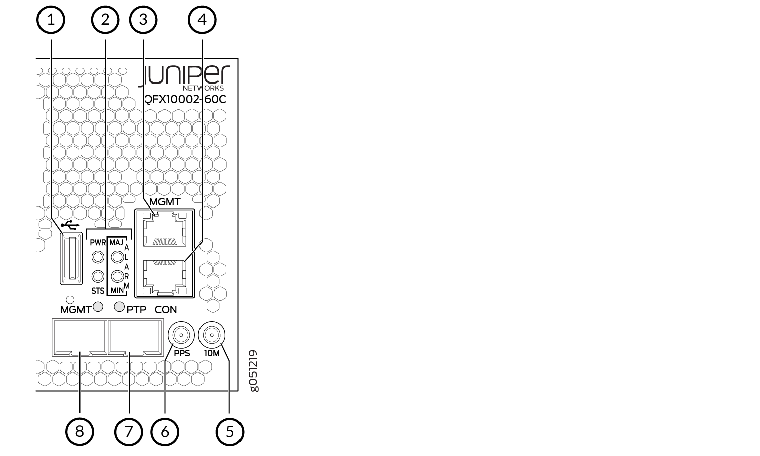
1 — USB port | 5 — 10 MHz SMB timing connector (10MHz) |
2 — Status LEDs–Power (PWR), status (STA), major alarm (MJR), and minor alarm (MIN). | 6 — 10 Hz pulses-per-second (PPS) SubMiniature B (SMB) connector for input and output measuring of the timing drift to and from a grandmaster clock |
3 — em0–RJ-45 (1000BASE-T) management Ethernet port (MGMT). | 7 — PTP Ethernet–SFP (1000BASE-T) port (ETH) |
4 — RJ-45 console port (CON) to support RS-232 serial ports. | 8 — em1–SFP management Ethernet port (MGMT). |
See Also
QFX10002 Management Port LEDs
There are two managements ports on a QFX10002 that have LEDs that indicate link status and link activity. These two ports, located on the management panel next to the access ports, are both labeled MGMT. The top management port is for 10/100/1000 BASE-T connections and the lower port is for 10/100/1000 BASE-T and small-form pluggable (SFP) 1000 BASE-X connections (see Figure 6). The copper, RJ45, port has separate LEDs for status and activity. The fiber, SFP, port has a combination link and activity LED.
1 — Status LED (RJ45) | 3 — Green indicates the link is up; blinking indicates activity (SFP) |
2 — Activity LED (RJ45) |
Table 1 and Table 2 describes the management port LEDs.
|
LED |
Color |
State |
Description |
|---|---|---|---|
|
Link/Activity |
Unlit |
Off |
No link is established, there is a fault, or the link is down. |
|
Yellow |
Blinking or flickering |
A link is established, and there is link activity. |
|
|
Status |
Unlit |
Off |
Either the port speed is 10 M or the link is down. |
|
Green |
On steadily |
The port speed is 1000 M. |
|
|
LED |
Color |
State |
Description |
|---|---|---|---|
|
Link/Activity |
Unlit |
Off |
No link is established or the link is down. |
|
Green |
On steadily |
Link is up and there is no activity. |
|
|
Green |
Blinking |
A link is established, and there is link activity. |
QFX10002 Chassis Status LEDs
The QFX10002 has four status LEDs on the port side of the chassis, next to the access ports (see Figure 7).
1 — PWR | 3 — MIN |
2 — MJR | 4 — STA |
Table 3 describes the chassis status LEDs on a QFX10002, their colors and states, and the status they indicate.
|
Name |
Color |
State |
Description |
|---|---|---|---|
|
PWR–Alarm |
Unlit |
Off |
The switch is powered off; no power to the device. |
|
Green |
On steadily |
Power is working correctly. |
|
|
Yellow |
Blinking |
There is a problem with chassis power. Power off the QFX10002 by setting the AC power source outlet to the OFF (O) position, or unplugging the AC power cords. Correct any voltage issues. Power on the QFX10002 and monitor the power supply and fan LEDs to help determine where the error is occurring. If there is any CPU power failure, the system will not boot. |
|
|
STA–Status |
Unlit |
Off |
The switch is powered off or halted. |
|
Green |
On steadily |
Junos OS for QFX Series is loaded on the switch. |
|
|
Green |
Blinking |
The beacon feature is enabled on the switch. This feature
is enabled using the |
|
|
Yellow |
Blinking |
The switch detects a fault. |
|
|
MJR–Major alarm |
Unlit |
Off |
There are no major alarms. |
|
Red |
On steadily |
A major hardware fault has occurred, such as a temperature alarm or power failure, and the switch has halted. |
|
|
MIN–Minor alarm |
Unlit |
Off |
There are no minor alarms. |
|
Yellow |
On steadily |
A minor alarm has occurred, such as a software error. |
For power and temperature alarms, you can use the show
chassis environment fpc operational mode command to get detailed
information on the internal state of the chassis. For example:
user@device> show chassis environment fpc

FPC 0 status:
  State                      Online
  Temperature                51 degrees C / 123 degrees F
  Voltage:
    PE0 VDD Core 0.9V            949 mV
    PE0 AVDD 1.0V               1000 mV
    PE0 HMC VDD 0.9V             897 mV
    PE0 HMC AVDD 1.2V           1197 mV
    PE01 HMC VDD 1.2V           1197 mV
    PE1 VDD Core 0.9V            949 mV
    PE1 AVDD Core 1.0V           999 mV
    PE1 HMC VDD 0.9V             899 mV
    PE1 HMC AVDD 1.2V           1197 mV
    PE2 VDD Core 0.9V            950 mV
    PE2 AVDD Core 1.0V           999 mV
    PE2 HMC VDD 0.9V             897 mV
    PE2 HMC AVDD 1.2V           1197 mV
    PE23 HMC AVDD 1.2V          1197 mV
    PE3 VDD Core 0.9V            949 mV
    PE3 AVDD Core 1.0V           999 mV
    PE3 HMC VDD 0.9V             899 mV
    PE3 HMC AVDD 1.2V           1200 mV
    PE4 VDD Core 0.9V            949 mV
    PE4 AVDD Core 1.0V           999 mV
    PE4 HMC VDD 0.9V             899 mV
    PE4 HMC AVDD 1.2V           1197 mV
    PE45 HMC AVDD 1.2V          1197 mV
    PE5 VDD Core 0.9V            949 mV
    PE5 AVDD Core 1.0V          1000 mV
    PE5 HMC VDD 0.9V             899 mV
    PE5 HMC AVDD 1.2V           1200 mV
    XMB VDD 3.3V                3316 mV
    MAIN VDD 3.3V               3298 mV
    RT VDD 1.0V                  999 mV
    MAIN VDD 2.5V               2502 mV
    MAIN PFE 1.5V               1502 mV
    PE6 VDD Core 0.9V            949 mV
    PE6 AVDD 1.0V               1000 mV
    PE6 HMC VDD 0.9V             897 mV
    PE6 HMC AVDD 1.2V           1204 mV
    PE67 HMC VDD 1.2V           1197 mV
    PE7 VDD Core 0.9V            949 mV
    PE7 AVDD Core 1.0V           999 mV
    PE7 HMC VDD 0.9V             897 mV
    PE7 HMC AVDD 1.2V           1197 mV
    PE8 VDD Core 0.9V            949 mV
    PE8 AVDD Core 1.0V           999 mV
    PE8 HMC VDD 0.9V             897 mV
    PE8 HMC AVDD 1.2V           1200 mV
    PE78 HMC AVDD 1.2V          1197 mV
    PE9 VDD Core 0.9V            950 mV
    PE9 AVDD Core 1.0V           999 mV
    PE9 HMC VDD 0.9V             897 mV
    PE9 HMC AVDD 1.2V           1200 mV
    PE10 VDD Core 0.9V           949 mV
    PE10 AVDD Core 1.0V          999 mV
    PE10 HMC VDD 0.9V            899 mV
    PE10 HMC AVDD 1.2V          1200 mV
    PE910 HMC AVDD 1.2V         1200 mV
    PE11 VDD Core 0.9V           950 mV
    PE11 AVDD Core 1.0V          999 mV
    PE11 HMC VDD 0.9V            899 mV
    PE11 HMC AVDD 1.2V          1200 mV
    PF0 VDD Core 0.9V            950 mV
    PF0 AVDD Core 1.0V           999 mV
    PF1 VDD Core 0.9V            950 mV
    PF1 AVDD Core 1.0V           999 mV
    XDB VDD 3.3V                3298 mV
    XDB RT VDD 1.0V              999 mV
    MEZZ VDD 2.5V               2502 mV
    MEZZ PFE 1.5V               1502 mV
    MEZZ GEX 1.0V                999 mV
    VCC 1.0V                    1009 mV
    VCC 0.85V                    862 mV
    VDD RAIL 12.0V                 0 mV
    VCC 1.8V                    1793 mV
    VDD 1.2V                    1215 mV
    PCH VCC 1.0V                 999 mV
    CPU VCC 1.8V                1803 mV
    BIAS 1 3.3V                 3312 mV
    AUX VCC 5.0V                4165 mV
    DDR VDD 1.5V                1499 mV
    VTT SA CPU 0.8V              803 mV
    VTT CPU 1.05V               1048 mV
    CORE CPU 1.0V                940 mV
    PCH VCC 1.5V                1509 mV
    PCH VCC 1.05V               1058 mV
    VDD 2.5V                    2508 mV