Help us improve your experience.

Let us know what you think.

Do you have time for a two-minute survey?


Connecting the PTX5000 to DC Power

Tools and Parts Required to Provide DC Power to the PTX5000

If you have a DC-powered router, gather the tools required to connect the PTX5000 to DC power:

  • 7/16-in. (11-mm) nut driver, between 23 lb-in. to 25 lb-in. (2.6 Nm to 2.8 Nm) tightening torque, for tightening nuts to the terminal studs.

    CAUTION:

    You must use an appropriate torque-controlled tool to tighten the nuts. Applying excessive torque damages the terminal studs. The maximum torque that may be applied to this nut is 62 lb-in. (7 Nm).

  • Phillips (+) screwdriver, number 2

  • DC power cables, which you must provide

  • DC power lugs

Installing the PTX5000 Cable Management System for a High Capacity DC PDU

Identifying the Parts of the Cable Management System

Note:

You cannot install this cable management system on a two-post rack.

  1. Remove the cable management system parts from the accessories kit in the shipping crate.
  2. Identify all the parts of the cable management system.
    • Two comb panel assemblies—the comb assembly, fixed to the extension panel with four screws, is detachable. See Figure 1 for left and right side views of the cable manager.

    • Four number 12 or M6 screws to install the comb panel assembly to the rack (not provided).

Figure 1: Cable Manager for a PTX5000 with High Capacity Power SystemCable Manager for a PTX5000 with High Capacity Power System
  1

Comb assembly

  3

Extension panel—Outside piece

  2

Extension panel—Inside piece


Installing the Cable Management Comb Assembly with Extension

Note:

Ensure that while mounting the PTX5000 chassis on the four-post rack, you leave at least 1.75 in. (4.45 cm) between the bottom of the PTX5000 chassis and the floor, so that there is enough space to install the High Capacity DC power system and to connect the cables.

To install the comb assembly to the rack:

  1. Attach an electrostatic discharge (ESD) grounding strap to your bare wrist, and connect the strap to one of the ESD points on the chassis.
  2. Align a cable manager assembly for one PDU against the rack vertically. Move the comb assembly up or down so that the mounting holes are aligned to the mounting holes on the rack.
    Note:

    The cable manager assembly is installed with the side wall of the comb assembly closer to the PDU but you can also install it with the side wall away from the PDU. The cable manager is symmetric in both positions. It might be easier for you to handle the mounting screws if the extension piece side wall is closer to the PDU as shown in Figure 2. You might have to remove the comb assembly from the extension pieces and reinstall the comb assembly with the extension pieces upside down, so that the side wall is closer to the PDU.

  3. Secure the cable manager assembly to the rack by placing four screws and tightening them using a number 3 Phillips (+) screwdriver. To widen the cable management comb assembly extension, see Widening the Cable Management Comb Assembly Extension
    Note:

    If the provided screws are not compatible with your rack, you might have to use different types of screws (such as metric screws).

    CAUTION:

    The maximum torque that may be applied to the provided number 12 screws is 30.0 lb-in. (3.4 Nm).

  4. Similarly, secure the cable manager for the other PDU.

  5. Connect power cables to the PDU (see Connecting Power to the PTX5000 High Capacity DC PDUs ).
  6. Route the power cables through the comb assembly. Ensure that each row of cables from the PDU is passed through the same row of the comb. For example, route the bottom row cables from the PDU through the bottom comb (see Figure 3). You can secure the cables by tie-wrapping the cables to the comb.
Figure 2: Installing the Cable Manager on the Four-post RackInstalling the Cable Manager on the Four-post Rack
Figure 3: Routing Power Cables Through the Comb AssemblyRouting Power Cables Through the Comb Assembly

Widening the Cable Management Comb Assembly Extension

Note:

The cable manager comb assembly extension is fixed at the minimum (default) position when shipped. You can widen the comb assembly, if the rear edge of the PTX5000 chassis extends out from the rack post and you do not have enough space to route the cables with the default comb assembly extension width.

To widen the comb assembly extension:

  1. Unfasten the screws that join the two plates of the cable manager extension panel assembly. Realign the plates along the next set of holes so that the extension is at the maximum length. See Figure 1.
  2. Reassemble the extension plates by fastening the six screws by using a number 2 Phillips (+) screwdriver.
    Note:

    Ensure that you fasten at least two rows of screws (four screws on each extension bracket assembly) for required strength to hold the extension plates.

  3. See Installing the Cable Management Comb Assembly with Extension to install the cable management comb assembly.
    CAUTION:

    The maximum torque that may be applied to these screws is 9.0 lb-in. (1.0 Nm).

Installing the Cable Management Comb Assembly Without Extension

Note:

You can use only the comb assembly without the extension, if the rear edge of the PTX5000 chassis is aligned with the four-post rack. In such a scenario, only the comb assembly is sufficient to route the cables.

To install the comb assembly on the four-post rack:

  1. Attach an electrostatic discharge (ESD) grounding strap to your bare wrist, and connect the strap to one of the ESD points on the chassis.
  2. Unfasten the four screws attaching the comb assembly to the extension manager by using a Phillips (+) screwdriver and separate the comb assembly from the extension.
  3. Align the comb assembly for one PDU against the rack vertically. Move the comb assembly up or down so that the mounting holes are aligned to the mounting holes on the rack.
  4. Secure the comb assembly to the rack by using the four screws that were removed. See Figure 4.
    Note:

    If the provided screws are not compatible with your rack, you might have to use different types of screws (such as metric screws).

    CAUTION:

    The maximum torque that may be applied to the provided number 12 screws is 30.0 lb-in. (3.4 Nm).

  5. Similarly, secure the comb assembly to the rack for the other PDU.
  6. Route the power cables through the comb assembly. Ensure that you route each row of cables from the PDU through the corresponding row of the comb (see Figure 3).
Figure 4: Installing Comb Assembly Without ExtensionInstalling Comb Assembly Without Extension

Connecting Power to the PTX5000 60-A DC Input Power Trays

To connect the DC source power cables to the 60-A DC inputs:

  1. Verify that a properly rated customer-site circuit breaker for each DC power cable has been installed. See PTX5000 DC Power Electrical Safety Guidelines in the PTX5000 Packet Transport Router Hardware Guide for more information.
  2. Switch off the customer-site circuit breakers. Ensure that the voltage across the DC power source cable leads is 0 V and that there is no chance that the cable leads might become active during installation.
  3. Verify that a licensed electrician has attached appropriate cable lugs to the DC power cables. See PTX5000 DC Power Cable and Lugs Specifications in the PTX5000 Packet Transport Router Hardware Guide for more information.
  4. Attach an electrostatic discharge (ESD) grounding strap to your bare wrist, and connect the strap to one of the ESD points on the chassis.
  5. Switch the input power switches on the PDU faceplate to the off (O) position.
  6. Loosen the captive screw that fastens the input power tray to the PDU .
  7. Grasp the metal handle of the input power tray, and pull it out to remove the input power tray from the PDU (see Figure 5. The 60-A DC input power tray weighs 1.6 lb (0.7 kg).
    Figure 5: Removing the 60-A DC Input Power TrayRemoving the 60-A DC Input Power Tray
  8. Use a Phillips (+) screwdriver to loosen the screw on the metal input power tray cover.
  9. Open the metal input power tray cover.
  10. Loosen the cable restraints.
  11. Remove the nuts from the DC power terminal studs.
  12. Route the positive (+) DC source power cable through the cable restraint, and connect it to the RTN –1 input terminal (see Figure 6). Using a 7/16-in. (11-mm) nut driver, tighten the nut to secure the cable lug to the input terminal (see Figure 7).
    CAUTION:

    You must use an appropriate torque-controlled tool to tighten the nuts. Applying excessive torque damages the terminal studs and power supply. The maximum torque that may be applied to this nut is 99 lb-in. (11 Nm).

    Figure 6: 60-A DC Input Terminals60-A DC Input Terminals
    Figure 7: Connecting the DC Source Power Cable Lugs to an Input Power TrayConnecting the DC Source Power Cable Lugs to an Input Power Tray
    CAUTION:

    You must ensure that power connections maintain the proper polarity. The power source cables might be labeled (+) and (–) to indicate their polarity. There is no standard color coding for DC power cables. The color coding used by the external DC power source at your site determines the color coding for the leads on the power cables that attach to the terminal studs on each power supply.

    CAUTION:

    All inputs on the DC PDU in slot PDU0 must be powered by dedicated power feeds derived from feed A, and all inputs on the DC PDU in slot PDU1 must be powered by dedicated power feeds derived from feed B. This configuration provides the commonly deployed A/B feed redundancy for the system.

  13. Route the positive (+) DC source power cable through the cable restraint, and connect it to the RTN –2 input terminal (see Figure 6). Using a 7/16-in. (11-mm) nut driver, tighten the nut to secure the cable lug to the input terminal.
  14. Route the negative (–) DC source power cable through the cable restraint, and connect it to the -48 V –1 input terminal (see Figure 6). Using a 7/16-in. (11-mm) nut driver, tighten the nut to secure the cable lug to the input terminal.
  15. Route the negative (–) DC source power cable through the cable restraint, and connect it to the -48 V –2 input terminal (see Figure 6). Using a 7/16-in. (11-mm) nut driver, tighten the nut to secure the cable lug to the input terminal (see Figure 7).
  16. Tighten the cable restraints over the DC power cables.
  17. Verify that the source power cables are connected to the appropriate terminal: the positive (+) source cable to the return terminals (labeled RTN) and the negative (–) source cable to the input terminals (labeled –48V).
  18. Close the input power tray cover, and secure it with the screw.
  19. Insert the input power tray into the PDU (see Figure 8).
  20. Repeat the procedure for all input power trays in the PDU.
  21. Repeat the procedure for the other PDU.
  22. Verify that the DC power cables do not touch or block access to the components, and that they do not drape where people could trip on them.
Figure 8: Installing a 60-A DC Input Power TrayInstalling a 60-A DC Input Power Tray

Connecting Power to the PTX5000 120-A DC Input Power Trays

To connect the DC source power cables to the 120-A DC inputs:

  1. Ensure that the voltage across the DC power source cable leads is 0 V and that there is no chance that the cable leads might become active during installation.
  2. Attach an ESD grounding strap to your bare wrist, and connect the strap to one of the ESD points on the chassis.
  3. Switch the circuit breakers on the power distribution unit (PDU) faceplate to the off (O) position.
  4. Loosen the captive screw that fastens the input power tray to the PDU .
  5. Grasp the metal handle of the input power tray, and pull it out to remove the input power tray from the PDU (see Figure 9). The 120-A DC input power tray weighs 1.6 lb (0.7 kg).
    Figure 9: Removing the 120-A DC Input Power TrayRemoving the 120-A DC Input Power Tray
  6. Use a Phillips (+) screwdriver to loosen the screw on the metal input power tray cover.
  7. Open the metal input power tray cover.
  8. Loosen the cable restraints.
  9. Remove the nuts from the DC power terminal studs.
  10. Route the positive (+) DC source power cable lug through the left cable restraint.
  11. Secure the positive (+) DC source power cable lug to the RTN (return) terminal, located on the left, with a nut.

    Use a 10-mm nut driver to tighten the nut.

  12. Route the negative (–) DC source power cable lug through the right cable restraint.
  13. Attach the negative (–) DC source power cable lug to the –48V (input) terminal, located on the right (see Figure 10).

    Use a 10-mm nut driver to tighten the nut.

    CAUTION:

    You must use an appropriate torque-controlled tool to tighten the nuts. Applying excessive torque damages the terminal studs and power supply. The maximum torque that may be applied to this nut is 99 lb-in. (11 Nm).

    CAUTION:

    You must ensure that power connections maintain the proper polarity. The power source cables might be labeled (+) and (–) to indicate their polarity. There is no standard color coding for DC power cables. The color coding used by the external DC power source at your site determines the color coding for the leads on the power cables that attach to the terminal studs on each power supply.

    CAUTION:

    All inputs on the DC PDU in slot PDU0 must be powered by dedicated power feeds derived from feed A, and all inputs on the DC PDU in slot PDU1 must be powered by dedicated power feeds derived from feed B. This configuration provides the commonly deployed A/B feed redundancy for the system.

    Figure 10: Connecting the DC Source Power Cable Lugs to an Input Power TrayConnecting the DC Source Power Cable Lugs to an Input Power Tray
  14. Tighten the cable restraint over the DC power cables.
  15. Verify that the source power cables are connected to the appropriate terminal: the positive (+) source cable to the return terminal (labeled RTN) and the negative (–) source cable to the input terminal (labeled –48V).
  16. Close the input power tray cover, and secure it with the screw.
  17. Insert the input power tray into the PDU (see Figure 11).
  18. Repeat the procedure for all input power trays in the PDU.
  19. Repeat the procedure for the other PDU.
  20. Verify that the DC power cables do not touch or block access to the components, and that they do not drape where people could trip on them.
Figure 11: Installing a 120-A DC Input Power TrayInstalling a 120-A DC Input Power Tray

Connecting Power to the PTX5000 High Capacity DC PDUs

To connect the DC source power cables to the High Capacity DC inputs:

  1. Verify that a properly rated customer-site circuit breaker for each DC power cable has been installed. See PTX5000 DC Power Electrical Safety Guidelines in the PTX5000 Packet Transport Router Hardware Guide for more information.
  2. Switch off the customer-site circuit breakers. Ensure that the voltage across the DC power source cable leads is 0 V and that there is no chance that the cable leads might become active during installation.
  3. Verify that a licensed electrician has attached appropriate cable lugs to the DC power cables. See PTX5000 DC Power Cable and Lugs Specifications in the PTX5000 Packet Transport Router Hardware Guide for more information.
  4. Attach an ESD grounding strap to your bare wrist, and connect the strap to one of the ESD points on the chassis.
  5. Move the power switch to the standby () position.
  6. Unfasten the screw using a number 2 Phillips (+) screwdriver and remove the terminal block safety cover.
  7. Remove the nuts from the DC power terminal studs.
  8. Install heat-shrink tubing insulation around the power cables.

    To install heat-shrink tubing:

    1. Slide the tubing over the portion of the cable where it is attached to the lug barrel. Ensure that tubing covers the end of the wire and the barrel of the lug attached to it.

    2. Shrink the tubing with a heat gun. Ensure that you heat all sides of the tubing evenly so that it shrinks around the cable tightly.

    Figure 12 shows the steps to install heat-shrink tubing.

    Note:

    Do not overheat the tubing.

    Figure 12: How to Install Heat-Shrink Tubing How to Install Heat-Shrink Tubing
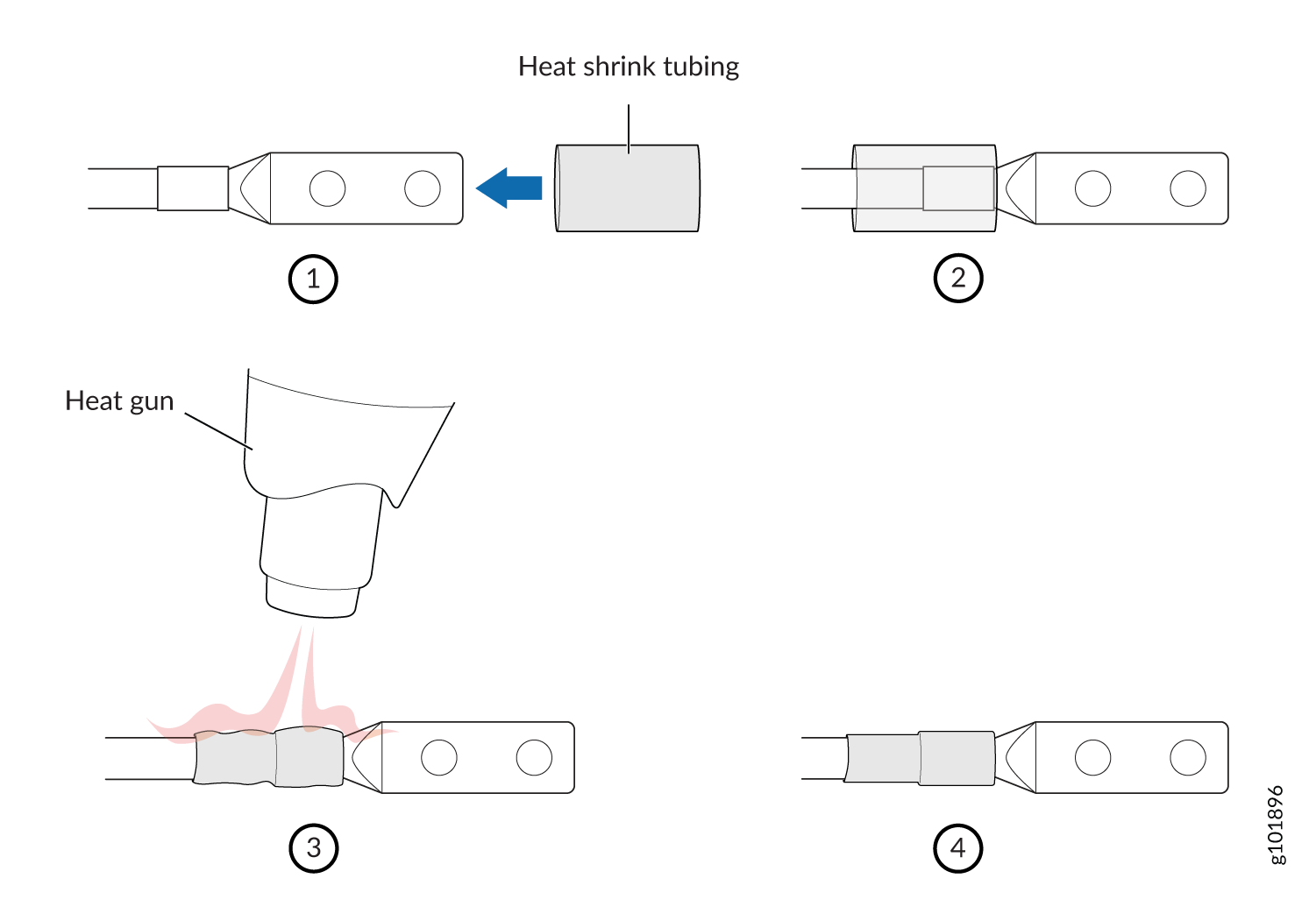
  9. Connect the positive (+) DC source power cable to the RTN input terminal (see Figure 13). Using a 7/16-in. (11-mm) nut driver, tighten the nut to secure the cable lug to the input terminal (see Figure 14).

    The terminal studs for each PSM are numbered on the faceplate. For example, the DC input terminals for PSM0 are PSM0_1 and PSM0_2, in the first and second rows of the terminal blocks. There are sixteen 60-A input terminals for the eight PSMs supported for each PDU.

    CAUTION:

    You must use an appropriate torque-controlled tool to tighten the nuts. Applying excessive torque damages the terminal studs and power supply. The maximum torque that may be applied to this nut is 65 lb-in. (7.3 Nm).

    Figure 13: High Capacity DC Input TerminalsHigh Capacity DC Input Terminals
    Figure 14: Connecting the DC Source Power Cable Lugs to an Input Power TerminalConnecting the DC Source Power Cable Lugs to an Input Power Terminal
    CAUTION:

    You must ensure that power connections maintain the proper polarity. The power source cables might be labeled (+) and (–) to indicate their polarity. There is no standard color coding for DC power cables. The color coding used by the external DC power source at your site determines the color coding for the leads on the power cables that attach to the terminal studs on each power supply.

    CAUTION:

    All inputs on the DC PDU in slot PDU0 must be powered by dedicated power feeds derived from feed A, and all inputs on the DC PDU in slot PDU1 must be powered by dedicated power feeds derived from feed B. This configuration provides the commonly deployed A/B feed redundancy for the system.

  10. Connect the negative (–) DC source power cable to the -48 V/60A input terminal (see Figure 14). Using a 7/16-in. (11-mm) nut driver, tighten the nut to secure the cable lug to the input terminal.
  11. Verify that the source power cables are connected to the appropriate terminal: the positive (+) source cable to the return terminals (labeled RTN) and the negative (–) source cable to the input terminals (labeled –48V/60A).
  12. Replace the terminal block safety cover and ensure that the cables fit into the slots of the safety cover.
  13. Repeat the procedure for the input power terminals for all the PSMs in the PDU.
  14. Repeat the procedure for the other PDU.
  15. Verify that the DC power cables do not touch or block access to the components, and that they do not drape where people could trip on them.