PTX12008 Routing and Control Board
Learn about the PTX12008 Routing and Control Board and its components and LEDs.
The Routing and Contol Board (RCB) is an integrated board and a single field-replaceable unit (FRU) that provides Routing Engine (RE) and Control Board (CB) functionality. The RE performs all route-processing functions, whereas the CB performs chassis control and management plane functions. The RCB performs routing protocol processes and software processes that control the router’s interface, the chassis components, system management functions, and user access to the router.
Each RCB provides all the functions needed to manage chassis operation:
-
System control functions such as monitoring environmental conditions
-
Routing Layer 2 and Layer 3 protocols
-
Communication to all components such as Flexible PIC Concentrators (FPCs), Forwarding Engine Boards (FEBs), power system components, and cooling system components
-
Transparent clocking
-
Alarm and logging functions
The router can run with one or two RCBs. When two RCBs are installed, one functions as the primary RCB and the other as the backup RCB. If the primary RCB is removed, the backup becomes the primary RCB given Graceful Routing Engine Switchover (GRES) is configured.
Routing and Control Board Functions
The RCB integrates the control plane and Routing Engine functions into a single management unit. Each RCB performs all the functions needed to manage the modular chassis operation:
-
System control functions such as monitoring environmental conditions
-
Routing Layer 2 and Layer 3 protocols
-
Communication to all components such as FPCs, Switch Interface Boards (SIBs), and power system components and cooling system components
-
Transparent clocking
-
Alarm and logging functions
Routing and Control Board Internal Components
Each RCB consists of the following internal components:
-
10-core 2.9-GHz CPU
-
256-GB DDR-4 RAM
-
Two 400-GB SSDs
Routing and Control Board Faceplate
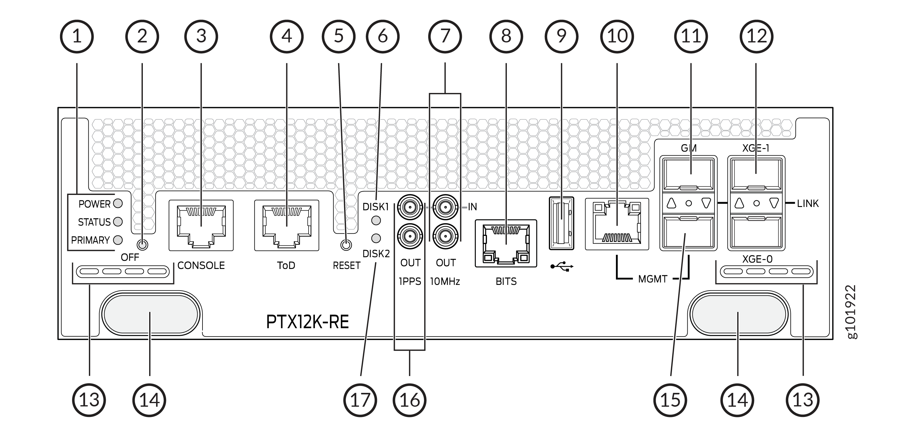
1 — Power, Status, and Primary─RCB status LEDs | 10 — MGMT—10/100/1000 BASE-T RJ-45 Ethernet management port (em0). You must use either the RJ-45 port or the SFP port as the management port. |
2 — Off—When the RCB is online, you can press the button for more than 4 seconds to power off the RCB. When the RCB is offline, you can press the button for more than 4 seconds to power on the RCB. | 11 — GM—Grandmaster clock port that connects the RCB to a timing device. |
3 — CONSOLE—Console port that connects the RCB to a system console by using a serial cable with an RJ-45 connector. | 12 — XGE-0 and XGE-1—SFP+ ports for connecting to external service appliances. |
4 — ToD—Time-of-Day (TOD) port that connects the RCB to external timing signal sources. | 13 — Airflow vents |
5 — RESET—Button to reset the RCB. A short press of the button reboots the RCB; the button press event is logged in the reset-reason logs. If you press the button for more than 10 seconds, the RCB reboots with BIOS recovery. | 14 — Ejector knobs |
6 — DISK1—Status LED for the solid-state drive 1. | 15 — Management port (em1) that supports small-form factor pluggable (SFP-X) transceivers. You must use either the RJ-45 port or the SFP port as the management port. |
7 — 10MHz—The 10-MHz timing connector that connects to external clock signal sources. | 16 — 1PPS—1-pulses per second (PPS) connector that connects to external clock signal sources. |
8 — BITS—The building-integrated timing system (BITS) port that connects to the external clocking interface for connecting to external clocking devices. | 17 — DISK2—Status LED for the solid-state drive 2. |
9 — USB port—Provides a removable media interface through which you can install Junos OS Evolved manually. |
Routing and Control Board Status Panel LEDs
The RCB status panel LEDs indicate the state of the RCB.
|
LED |
Color |
State |
Description |
|---|---|---|---|
|
POWER (Power) |
Green |
On steadily |
The RCB is receiving adequate power. |
|
Red |
Blinking |
The RCB has detected an error. |
|
|
None |
Unlit |
The RCB is not powered up. |
|
|
STATUS (Status) |
Green |
On steadily |
The RCB is online and functioning correctly. |
| Green | Slow blink | The RCB is booting. | |
|
Green |
Blinking |
Software is loading. |
|
|
Yellow |
Blinking |
The RCB has detected an error. |
|
|
None |
Unlit |
The RCB is offline. |
|
|
PRIMARY (Primary) |
Green |
On steadily |
The RCB is the primary RCB. |
|
None |
Unlit |
The RCB is the backup RCB. |
RJ-45 Management Port LEDs
The RJ-45 management port on the RCB labeled MGMT has LEDs that indicate the link status and link activity.
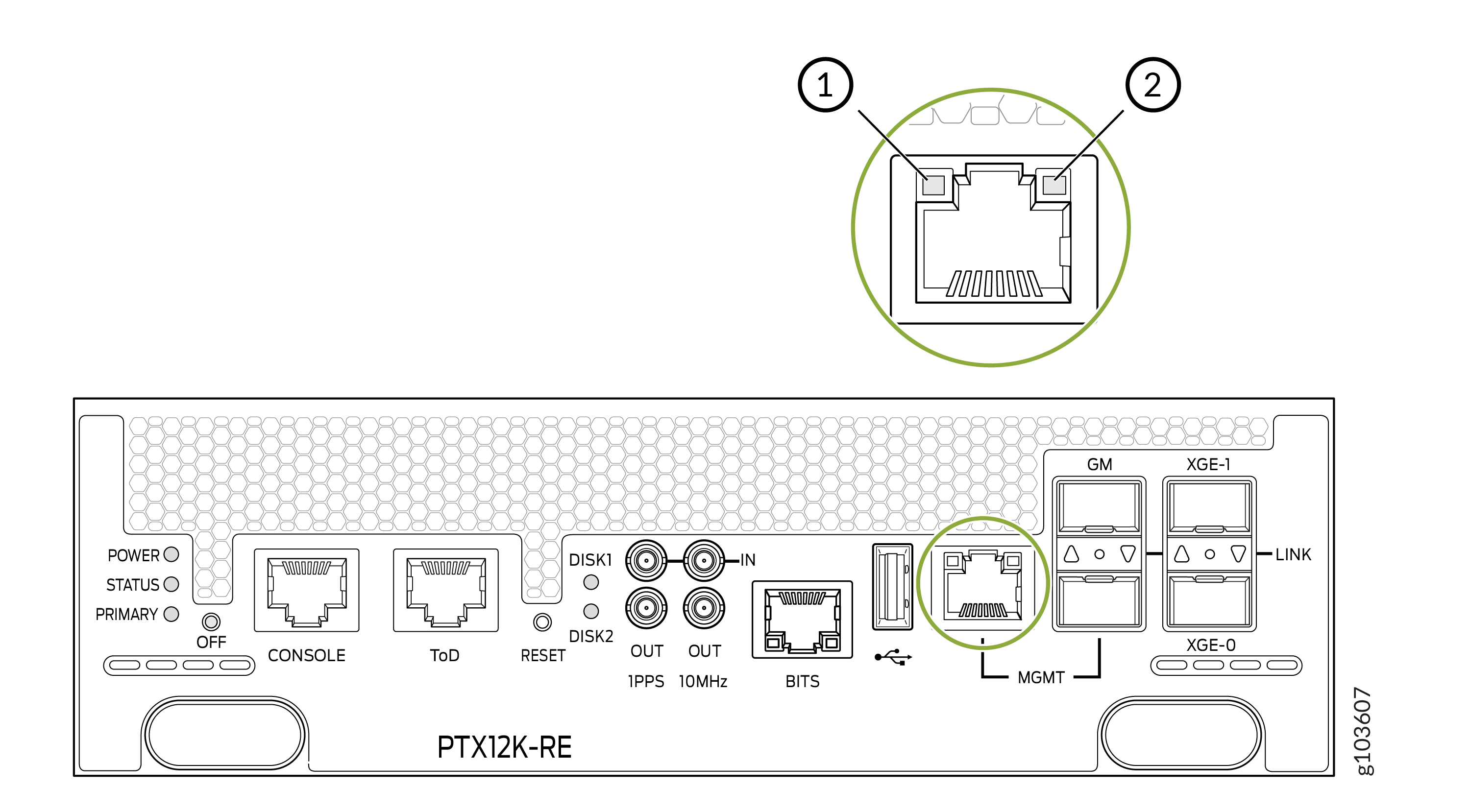
1 — Activity LED | 2 — Link LED |
|
LED |
Color |
State |
Description |
|---|---|---|---|
|
Link |
Unlit |
Off |
The link is down |
|
Green |
On steadily |
The port speed is 1000 MB. |
|
|
Green |
Blinking |
The port speed is 100 MB. |
|
|
Unlit |
Off |
The port speed is 10 MB or there is no link activity. |
|
|
Activity |
Unlit |
Off |
There is no link activity. |
|
Green |
Blinking |
There is link activity. |
SFP Management Port LED
The SFP management port on the RCB has an LED that indicate link status and link activity.
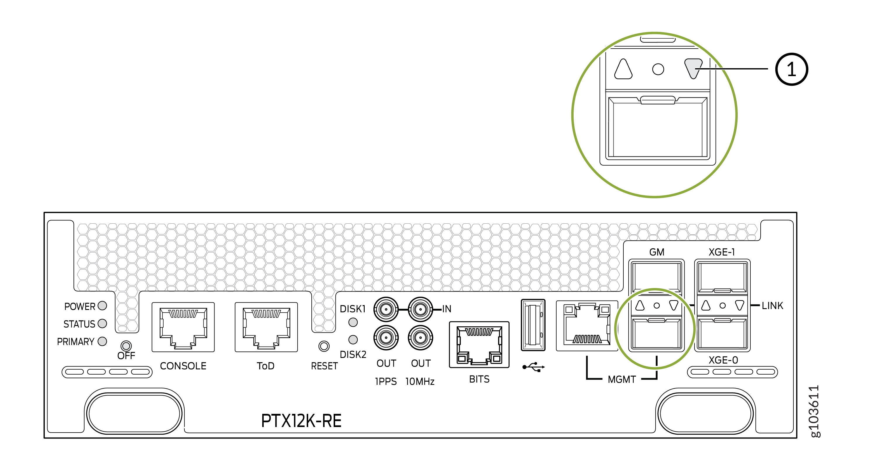
1 — Port LED |
|
Color |
State |
Description |
|---|---|---|
|
Green |
On steadily |
The port is enabled. |
|
Green |
Blinking |
There is link activity. |
|
Yellow |
Blipping |
The beacon function is enabled on the port. |
|
Yellow |
Blinking |
There is a fault in the port. |
|
Unlit |
Unlit |
The port is disabled. |
SSD LEDs
The solid-state drive (SSD) LEDs indicate the status of the secondary drive.
|
LED |
Color |
State |
Description |
|---|---|---|---|
|
DISK1 and DISK2 |
Green |
On steadily |
An SSD drive is present. |
|
Green |
Blinking |
The drive is active. |
|
|
Unlit |
Off |
A drive is not installed or a drive is installed, but there is no disk activity. |
BITS LED
The BITS LED indicates whether clocking is active.
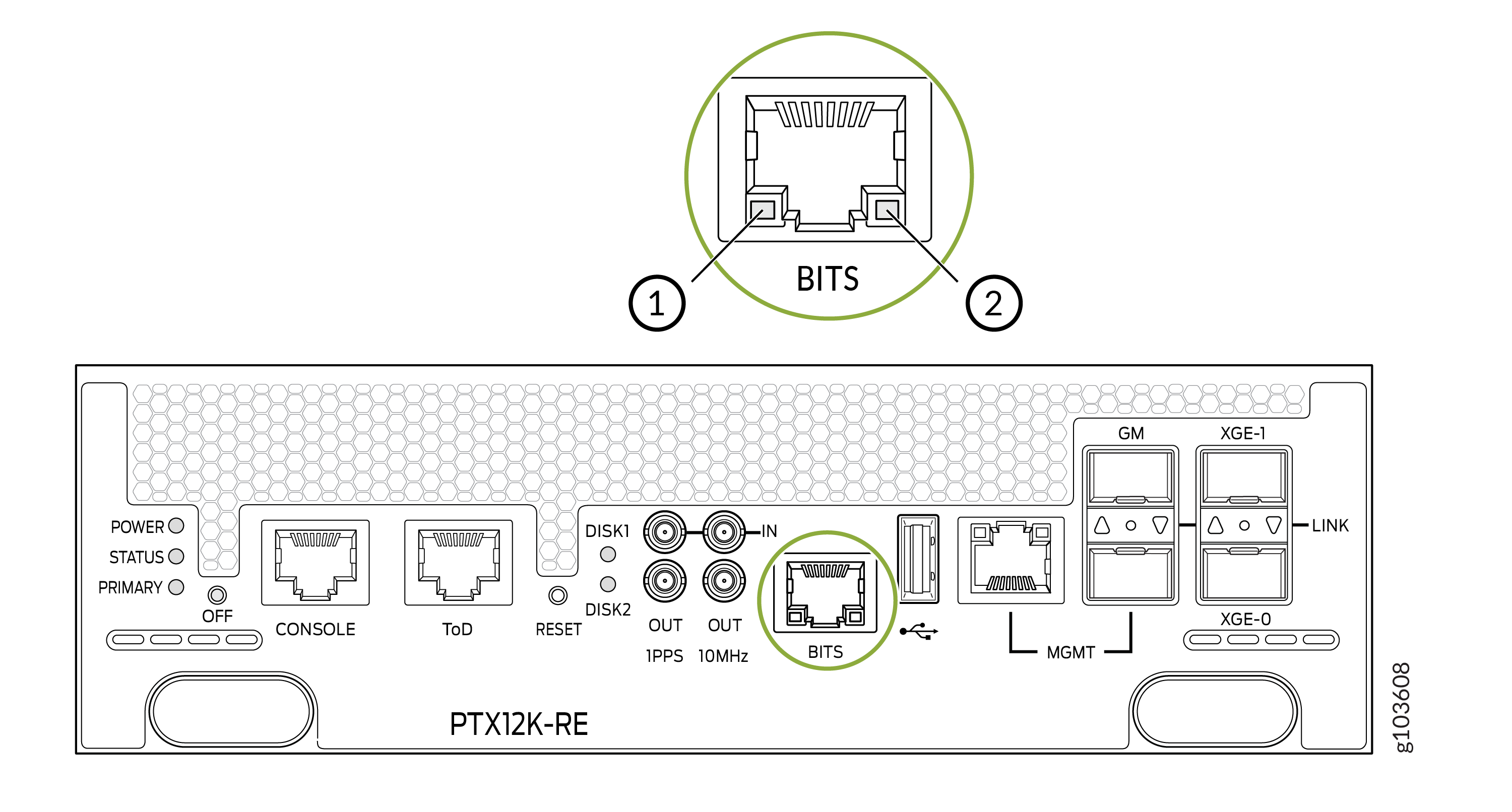
1 — Loss of clock LED | 2 — Active clock LED |
|
LED |
Color |
State |
Description |
|---|---|---|---|
|
Loss of clock |
Yellow |
On steadily |
An error has occurred. |
|
Unlit |
Off |
The clock is not configured. |
|
|
Active clock |
Green |
On steadily |
The clock is active. |
|
Unlit |
Off |
The clock is not configured. |
GM Port LED
The grandmaster clocking port (GM) LED shows the status of the GM port.
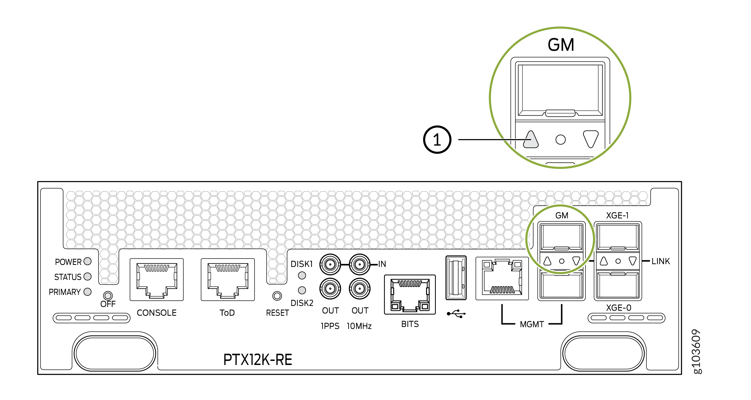
1 — GM Port LED |
|
LED |
Color |
State |
Description |
|---|---|---|---|
|
GM |
Green |
On |
The link is active. |
|
Yellow |
On |
An error has occurred. | |
|
Unlit |
Off |
A transceiver is not installed. |
XGE Ports LED
The XGE ports LED shows the status of the XGE0 and XGE1 ports.
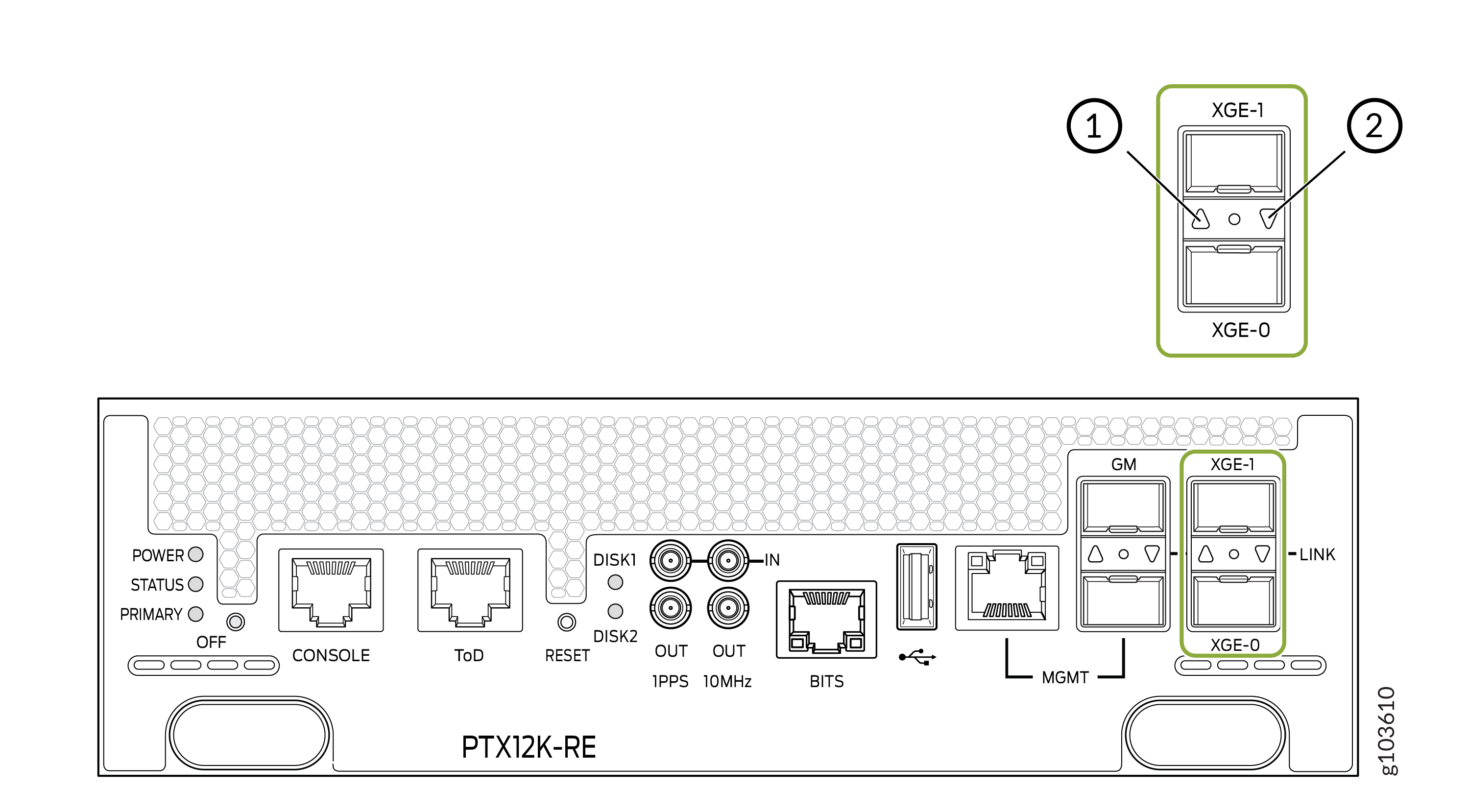
1 — Port LED for XGE-0 Port | 2 — Port LED for XGE-1 Port |
|
LED |
Color |
State |
Description |
|---|---|---|---|
|
XGE0 and XGE1 |
Green |
On |
The link is active. |
|
Green |
Blinking |
There is link activity. |
|
|
Yellow |
On |
An error has occurred. | |
|
Unlit |
Off |
A transceiver is not installed or the link is not active. |