Mount the PTX10016 by Using the JNP10004-RMK-4POST Rack Mount Kit
You can mount a PTX10016 router in a four-post closed frame rack or a four-post open frame rack by using a rack mount kit. The rack mount kit with the part number JNP10004-RMK-4POST is shipped by default. You can order the rack mount kit with the part number EX-MOD-RMK-4POST separately. In this topic, we describe how to mount the router by using the JNP10004-RMK-4POST rack mount kit.
Before you mount the PTX10016 router:
-
Prepare the site for installation as described in PTX10016 Site Preparation Checklist.
-
Unpack the router as described in Unpack the PTX10016 Shipping Pallet.
-
Review the chassis lifting guidelines in PTX10016 Chassis Lifting Guidelines.
Ensure that you have the following parts and tools available:
-
A mechanical lift rated for 1000 lb (453.6 kg)
-
32 rack mount screws appropriate for your rack to secure the mounting blades, mounting tray, chassis, and safety restraint to the rack (not provided)
-
A Phillips (+) screwdriver, number 1, 2, or 3, depending on the size of your rack screws (not provided)
The rack mount kit consists of the following components:
-
One mounting tray
-
Two mounting blades
-
One safety restraint
-
12 Phillips 8-32 x .375 flat-head screws
Install line cards and other components in the chassis only after you mount the chassis securely.
Before mounting the router on a rack, have a qualified technician verify that the rack is strong enough to support the router's weight and is adequately supported at the installation site.
If you are mounting multiple units on a rack, plan to mount the first router at the bottom of the rack. Mount the heaviest unit at the bottom of the rack and mount the other units from the bottom of the rack to the top in decreasing order of the weight of the units.
To mount the router:
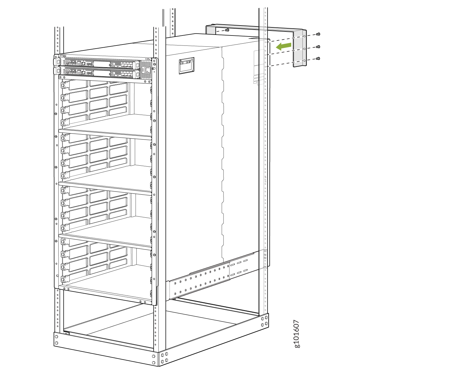
-
Attach the mounting blades to the front rack posts by using eight rack mount
screws appropriate for your rack and a screwdriver (see Figure 1).
Figure 1: Attach the Mounting Blades
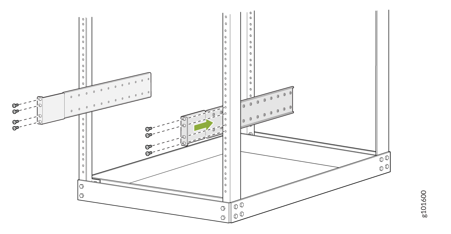
-
From the rear of the rack, slide the mounting tray into the rear posts of the
rack such that the mounting blades slide into the grooves on the mounting tray.
Attach the tray to the rear rack posts by using six rack mount screws
appropriate for your rack and a screwdriver (see Figure 2).
Figure 2: Attach the Mounting Tray
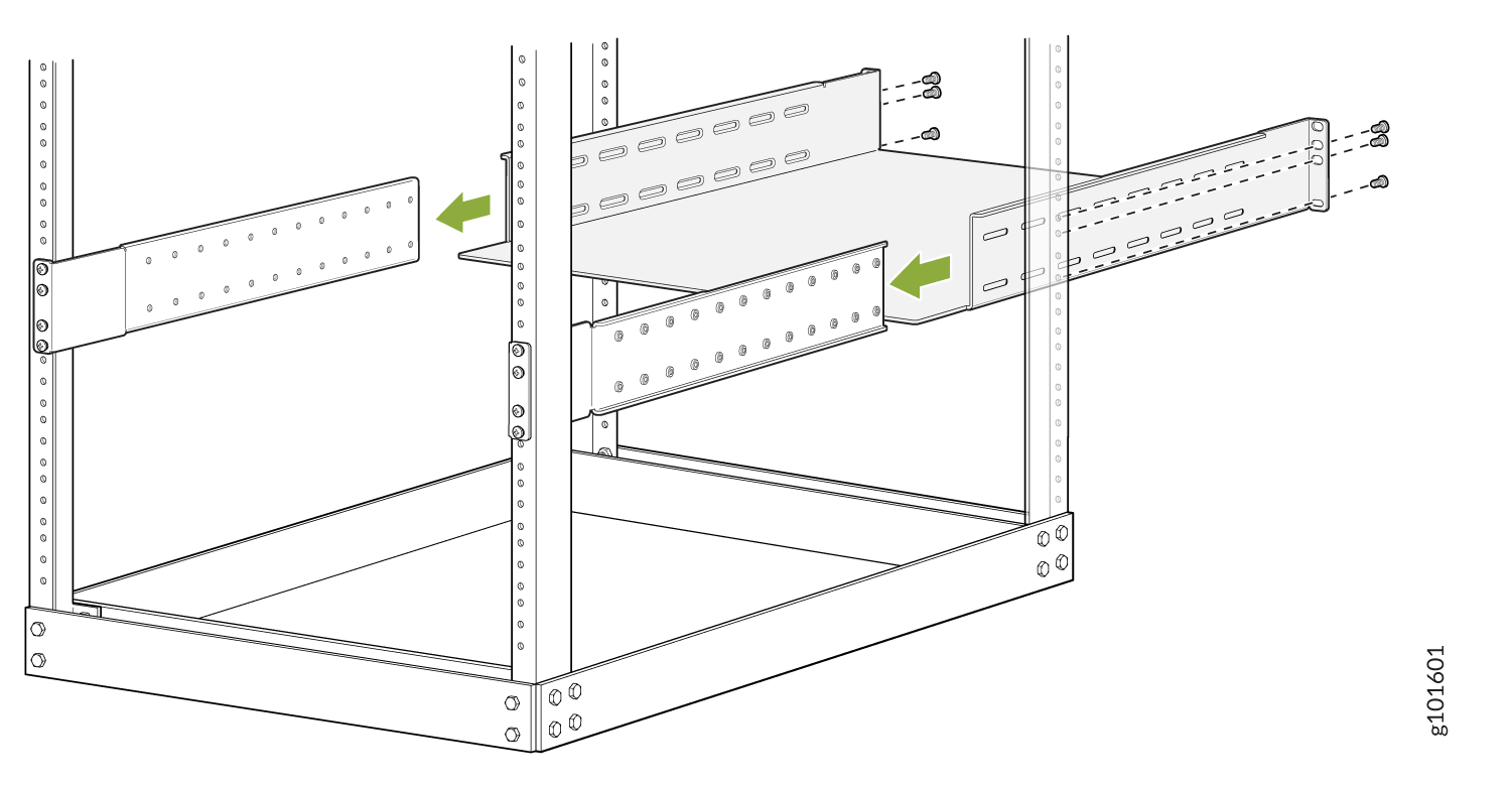
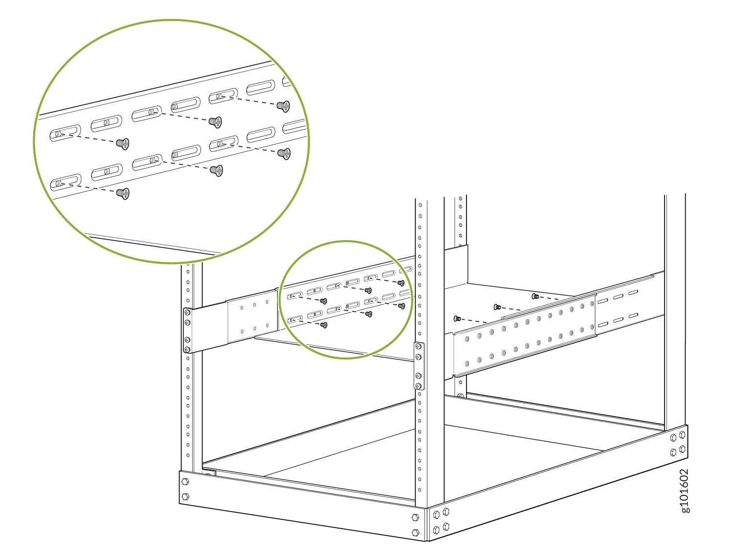
-
Attach the mounting blades to the tray with the 12 Phillips 8-32 x .375 in.
flat-head screws (see Figure 3).
Figure 3: Attach the Mounting Blades to the Mounting Tray
-
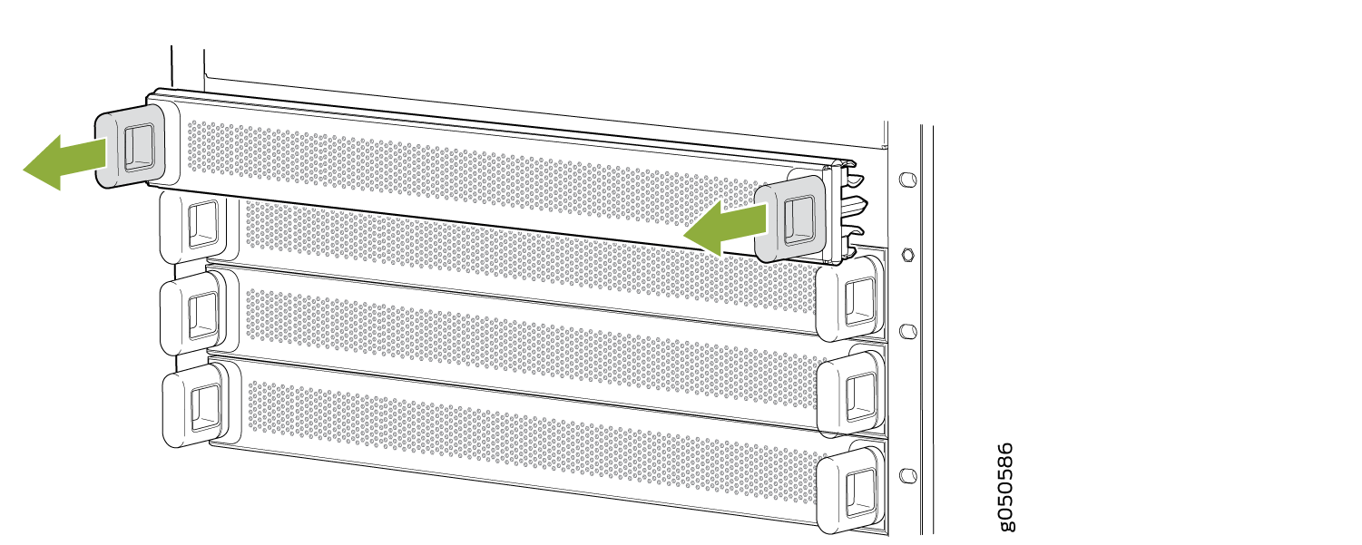
Remove the line card slot covers by grasping the handles and pulling the covers
straight out (see Figure 4).
Store the covers.
Figure 4: Remove the Line Card Slot Covers
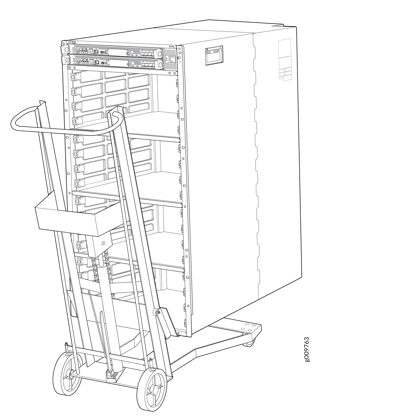
-
Load the router onto the lift, making sure it rests securely on the lift
platform (see Figure 5).
Figure 5: Load the PTX10016 onto a Mechanical Lift
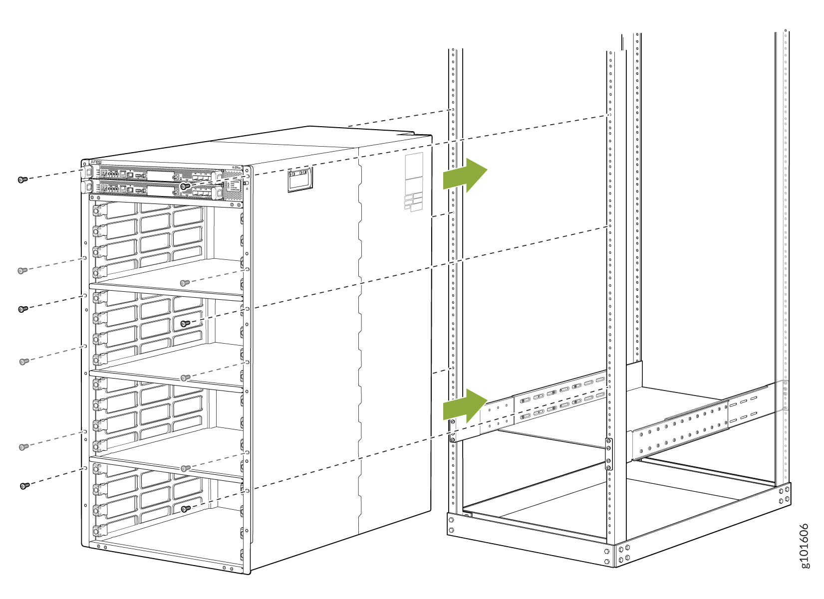
-
Attach the chassis to the rack by installing 12 rack mount screws through each
open flange hole and rack hole (see Figure 6).
Figure 6: Attach the Chassis to the Rack
-
Attach the restraint to the rack by installing six rack mount screws through
each open flange hole and rack hole (see Figure 7).
Tighten the screws.
Figure 7: Attach the Safety Restraint