PTX10003 Management Panel
The PTX10003-8T management panel is in the upper right corner of the port panel (see Figure 1).
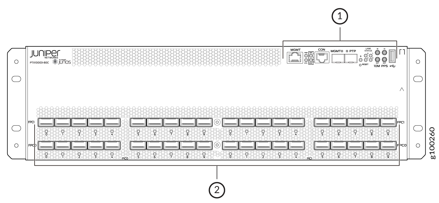
1 — Management panel | 2 — Port panel |
PTX10003 Management Panel Components
You manage the PTX10003 by using the Junos OS Evolved software CLI, which is accessible through the console and out-of-band management ports on the management panel. The management panel, located in the upper right corner of the port panel, has system status LEDs that alert you to minor and major alarms, and other issues with the router. It also has external clock synchronization ports and a USB port to support software installation and recovery. Figure 2 shows the management panel in detail.
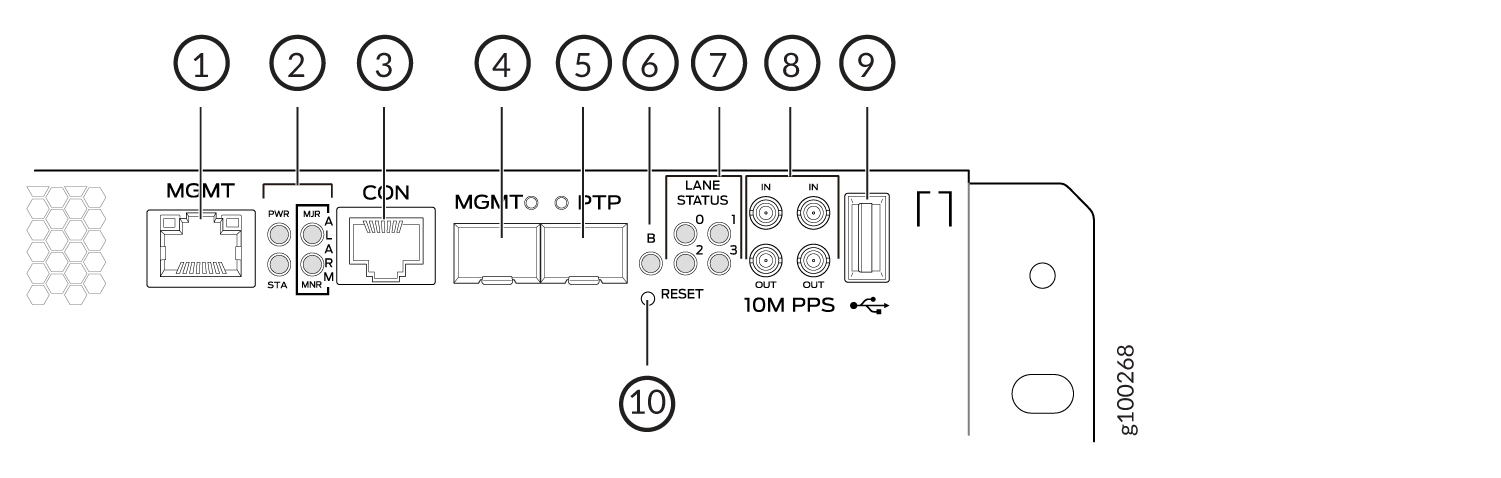
1 — RJ-45 Ethernet management port(MGMT) | 6 — Beacon LED |
2 — Power (PWR) Status (STA) and alarm LEDs (MJR= major alert; MNR=minor alert) | 7 — Four LANE STATUS LEDs numbered 0, 1, 2, 3 for lane identification of the QSFP channel. The lane ID LEDs work in conjunction with the activity LEDs that appear beneath the optics. These optics can support up to four independent lanes. Since there is only one LED per QSFP, the lane ID LEDs indicate which physical QSFP lane corresponds to the LED indicator that is currently active. |
3 — RJ-45 console UART (CON) port. An optional GPS Time of Day (TOD) is also supported. | 8 — Four co-axial input/output (IN/OUT SMB connectors for external 1PPS and 5MHz/10MHz simultaneous I/O bi-directional timing. BITS is not supported. |
4 — SFP (MGMT) port for 1G system management | 9 — USB 2.0 port for connection to the CPU |
5 — SFP (PTP) port for an IEEE 1588 PTP timing source | 10 — Reset (RESET) push button for resetting the CPU |
PTX10003 Management Panel LEDs
Table 1 describes the management panel LEDs on the PTX10003.
|
LED Name |
Color/State |
Definition |
|---|---|---|
|
RJ-45 10/100/1000 Management Port LED MGMT |
Off |
Link up, no activity |
|
Yellow/Blinking |
Link up, activity |
|
|
Power LEDs PWR |
Green/On |
Power is ok |
|
Yellow/Blinking |
Power fault |
|
|
Off |
Offline |
|
|
SFP Optic Management Port LED MGMT |
Green |
Link up, no activity |
|
Green/Blinking |
Link up, activity |
|
|
Off |
Link down |
|
|
PTP Port LED PTP |
Green |
Link up, no activity |
|
Green/Blinking |
Link, activity |
|
|
Off |
Link down |
|
|
Alarm LEDs MJR |
Red/On |
Alarm is active |
|
Off |
No alarm |
|
|
MNR |
Yellow/On |
Minor alarm is active |
|
No alarms |
Off |
No alarms are active |
|
Beacon (B) |
Blue/off |
Used as chassis locator |
|
LANE STATUS |
Green/off, 2x2 LED matrix |
Indicates which lane of optics corresponds to LED traffic indicator beneath optics. Upper left corner LED corresponds to lane 0, proceeding clock wise – lane 1,2,3 |
For power and temperature alarms, use the show chassis environment fpc
operational mode command to get detailed information on the internal state of the chassis.
For example:
user@device> show chassis environment fpc

FPC 0 status:
  State                      Online
  Temperature                51 degrees C / 123 degrees F
  Voltage:
    PE0 VDD Core 0.9V            949 mV
    PE0 AVDD 1.0V               1000 mV
    PE0 HMC VDD 0.9V             897 mV
    PE0 HMC AVDD 1.2V           1197 mV
    PE01 HMC VDD 1.2V           1197 mV
    PE1 VDD Core 0.9V            949 mV
    PE1 AVDD Core 1.0V           999 mV
    PE1 HMC VDD 0.9V             899 mV
    PE1 HMC AVDD 1.2V           1197 mV
    PE2 VDD Core 0.9V            950 mV
    PE2 AVDD Core 1.0V           999 mV
    PE2 HMC VDD 0.9V             897 mV
    PE2 HMC AVDD 1.2V           1197 mV
    PE23 HMC AVDD 1.2V          1197 mV
    PE3 VDD Core 0.9V            949 mV
    PE3 AVDD Core 1.0V           999 mV
    PE3 HMC VDD 0.9V             899 mV
    PE3 HMC AVDD 1.2V           1200 mV
    PE4 VDD Core 0.9V            949 mV
    PE4 AVDD Core 1.0V           999 mV
    PE4 HMC VDD 0.9V             899 mV
    PE4 HMC AVDD 1.2V           1197 mV
    PE45 HMC AVDD 1.2V          1197 mV
    PE5 VDD Core 0.9V            949 mV
    PE5 AVDD Core 1.0V          1000 mV
    PE5 HMC VDD 0.9V             899 mV
    PE5 HMC AVDD 1.2V           1200 mV
    XMB VDD 3.3V                3316 mV
    MAIN VDD 3.3V               3298 mV
    RT VDD 1.0V                  999 mV
    MAIN VDD 2.5V               2502 mV
    MAIN PFE 1.5V               1502 mV
    PE6 VDD Core 0.9V            949 mV
    PE6 AVDD 1.0V               1000 mV
    PE6 HMC VDD 0.9V             897 mV
    PE6 HMC AVDD 1.2V           1204 mV
    PE67 HMC VDD 1.2V           1197 mV
    PE7 VDD Core 0.9V            949 mV
    PE7 AVDD Core 1.0V           999 mV
    PE7 HMC VDD 0.9V             897 mV
    PE7 HMC AVDD 1.2V           1197 mV
    PE8 VDD Core 0.9V            949 mV
    PE8 AVDD Core 1.0V           999 mV
    PE8 HMC VDD 0.9V             897 mV
    PE8 HMC AVDD 1.2V           1200 mV
    PE78 HMC AVDD 1.2V          1197 mV
    PE9 VDD Core 0.9V            950 mV
    PE9 AVDD Core 1.0V           999 mV
    PE9 HMC VDD 0.9V             897 mV
    PE9 HMC AVDD 1.2V           1200 mV
    PE10 VDD Core 0.9V           949 mV
    PE10 AVDD Core 1.0V          999 mV
    PE10 HMC VDD 0.9V            899 mV
    PE10 HMC AVDD 1.2V          1200 mV
    PE910 HMC AVDD 1.2V         1200 mV
    PE11 VDD Core 0.9V           950 mV
    PE11 AVDD Core 1.0V          999 mV
    PE11 HMC VDD 0.9V            899 mV
    PE11 HMC AVDD 1.2V          1200 mV
    PF0 VDD Core 0.9V            950 mV
    PF0 AVDD Core 1.0V           999 mV
    PF1 VDD Core 0.9V            950 mV
    PF1 AVDD Core 1.0V           999 mV
    XDB VDD 3.3V                3298 mV
    XDB RT VDD 1.0V              999 mV
    MEZZ VDD 2.5V               2502 mV
    MEZZ PFE 1.5V               1502 mV
    MEZZ GEX 1.0V                999 mV
    VCC 1.0V                    1009 mV
    VCC 0.85V                    862 mV
    VDD RAIL 12.0V                 0 mV
    VCC 1.8V                    1793 mV
    VDD 1.2V                    1215 mV
    PCH VCC 1.0V                 999 mV
    CPU VCC 1.8V                1803 mV
    BIAS 1 3.3V                 3312 mV
    AUX VCC 5.0V                4165 mV
    DDR VDD 1.5V                1499 mV
    VTT SA CPU 0.8V              803 mV
    VTT CPU 1.05V               1048 mV
    CORE CPU 1.0V                940 mV
    PCH VCC 1.5V                1509 mV
    PCH VCC 1.05V               1058 mV
    VDD 2.5V                    2508 mV