Replace Fan Trays in the PTX10002-60MR
Maintaining the cooling system in the PTX10002-60MR includes removing and installing the fan trays.
We ship the router with 2+1 redundant fan modules preinstalled in the rear panel. Fan modules in the PTX10002-60MR are hot-removable and hot-insertable field-replaceable units (FRUs) installed on the rear panel of the chassis. You can remove and replace the fan modules without powering off the PTX10002-60MR or disrupting the device functions.
Remove a Fan Module from the PTX10002-60MR
Before you remove a fan module, ensure that you have taken the necessary precautions to prevent electrostatic discharge (ESD) damage (see Prevention of Electrostatic Discharge Damage).
Ensure that you have the following parts and tools available:
-
An ESD grounding strap—not provided
-
An antistatic bag or an antistatic mat—not provided
-
A Phillips (+) screwdriver, number 1—not provided
-
A replacement fan module
Replace the fan module within the time specified below to prevent components in the chassis from overheating and shutting down:
-
Device with 800 Gbps optics -
-
replace within 40 seconds at 40° C, Sea Level
-
replace within 90 minutes at 25° C, Sea Level
-
-
Device with 400 Gbps optics -
-
replace within 60 seconds at 40° C, Sea Level
-
replace within 90 minutes at 25° C, Sea Level
-
-
Device with 100 Gbps optics -
-
replace within 10 minutes at 40° C, Sea Level
-
replace within 90 minutes at 25° C, Sea Level
-
If you replace a fan module when the ambient temperature is below 96.8° F (36° C) and the power drawn by each transceiver installed in the router is below 25 W, none of the transceivers would shut down due to overheating. Before removing the fan module, ensure you have a replacement fan module available.
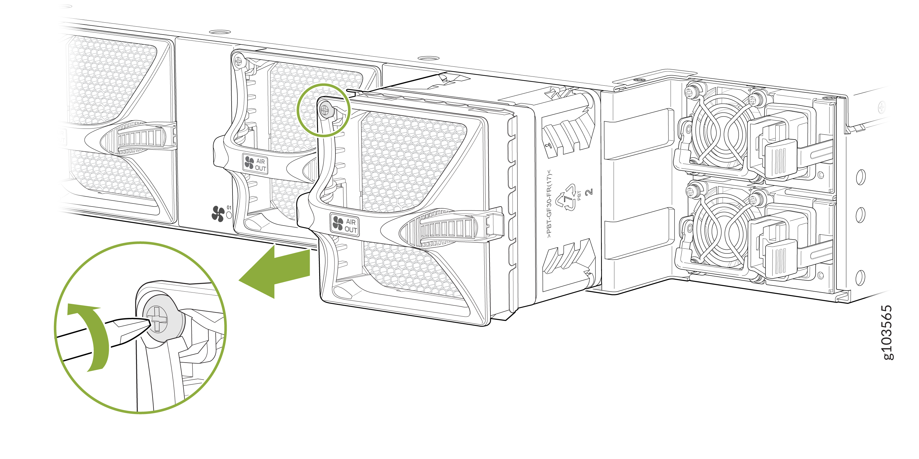
To remove a fan module:
-
Using the Phillips screwdriver, loosen the locking screw (3 or 4 turns to
the left).
Figure 1: Remove a Fan Module
When a fan module is removed, the CLI message Fan/Blower is
Absent is logged in the system log, and the system raises a
major alarm.
Install a Fan Module in the PTX10002-60MR
Before you install a fan module, ensure that you have taken the necessary precautions to prevent electrostatic discharge (ESD) damage (see Prevention of Electrostatic Discharge Damage).
Ensure that you have the following parts and tools available:
-
An ESD grounding strap—not provided
-
A Phillips (+) screwdriver, number 1—not provided
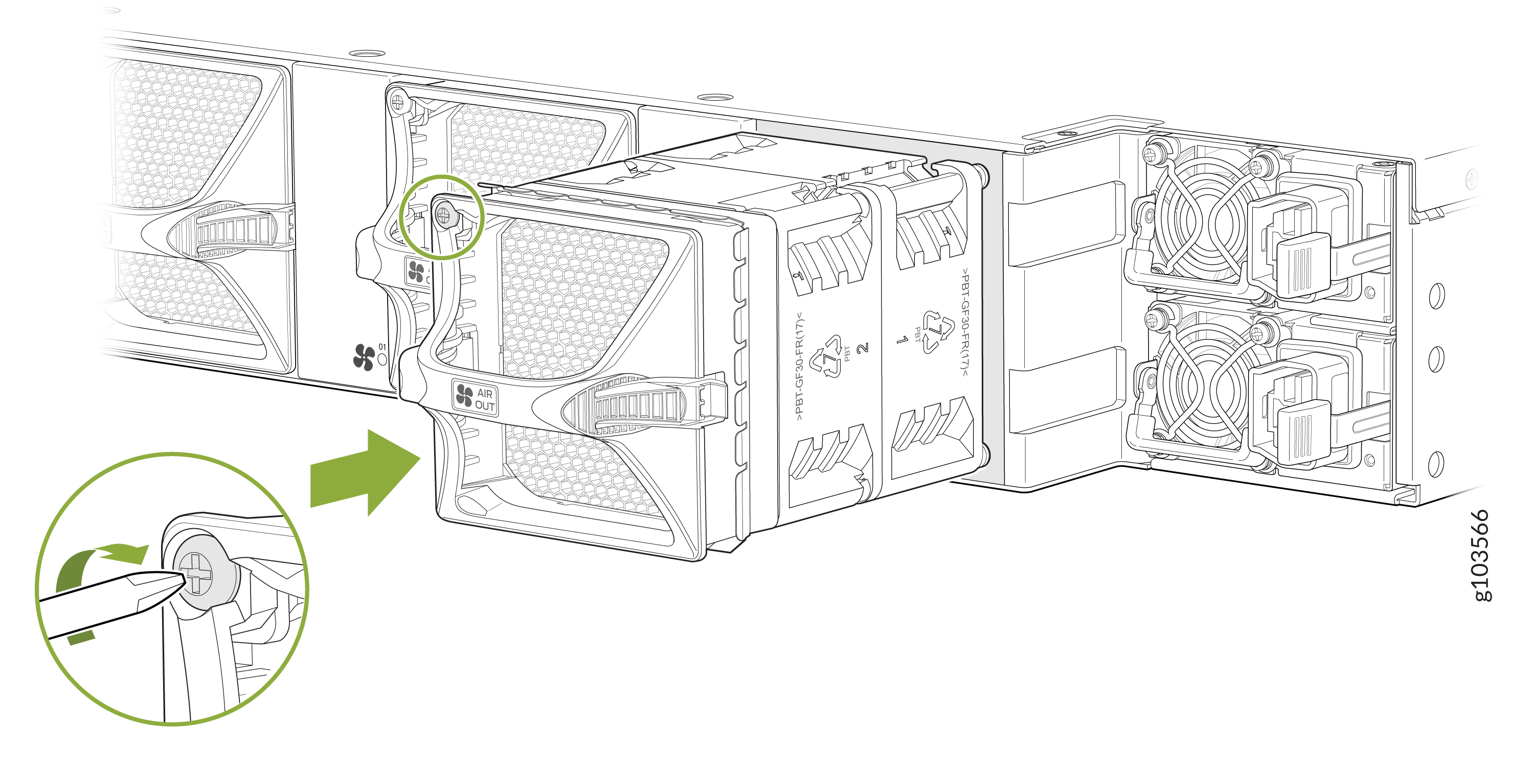
To install a fan module:
-
Align the module with the empty fan module slot on the rear panel of the
router and slide it in until it is fully seated.
Figure 2: Install a Fan Module