
PTX10002-60MR Models
This topic provides details of the PTX10002-60MR Router and its specifications, information on the number and types of ports in the router, and the components in the router shipment.
|
Model |
AC/HVAC/HVDC variant |
DC variant |
Front-to-back airflow variant |
Back-to-front airflow variant |
|---|---|---|---|---|
|
PTX10002-60MR |
✔ |
✔ |
✔ |
- |
Color coding and labeling system is used to identify the direction of cooling airflow in hot-swappable hardware components like fan trays and power supplies.
Airflow Direction Indicators
- Front-to-Back Airflow (AFO / Airflow Out)
- Visual Cue: Juniper Gold handle.
- Text Label: AIR OUT (meaning air exhausts out of this side of the component).
- Back-to-Front Airflow (AFI / Airflow In)
- Visual Cue: Juniper Azure Blue handle.
- Text Label: AIR IN (meaning air is pulled into this side of the component)
PTX10002-60MR
Components on the Front and Rear Panels
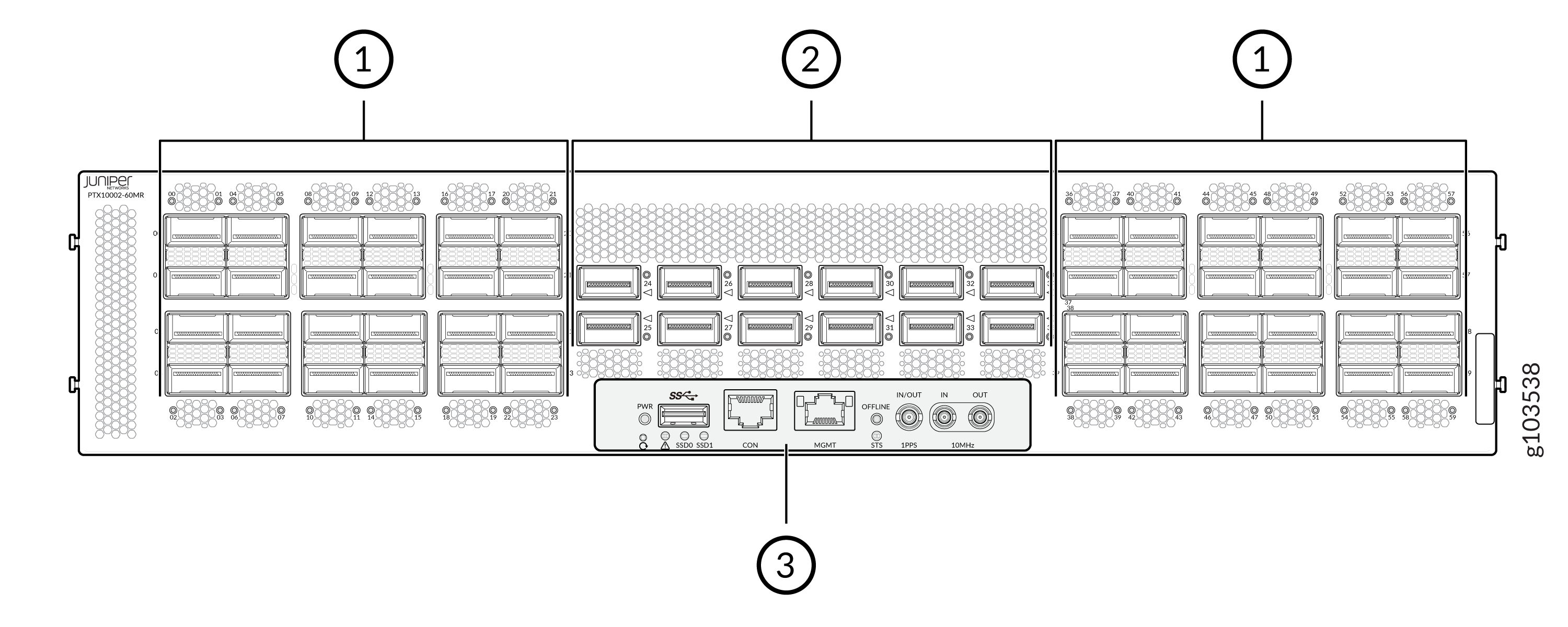
| Callout | Item | Description |
|---|---|---|
|
1 |
48 QSFP28 ports |
Quad Small Form-factor Pluggable 28 (QSFP28) ports are high-density, hot-pluggable interfaces designed for 100-Gbps data rates. Each port uses 4 lanes, each lane carrying up to 28 Gbps (often 25 Gbps). |
|
2 |
12 QSFP112 DD ports |
High-density, eight lane interface designed for 800G networking, supporting 100G PAM4 per lane. These ports offer backward compatibility with 400G, 200G, and 100G modules. |
|
3 |
Front panel controls |
Front panel controls. See Figure 2. |
|
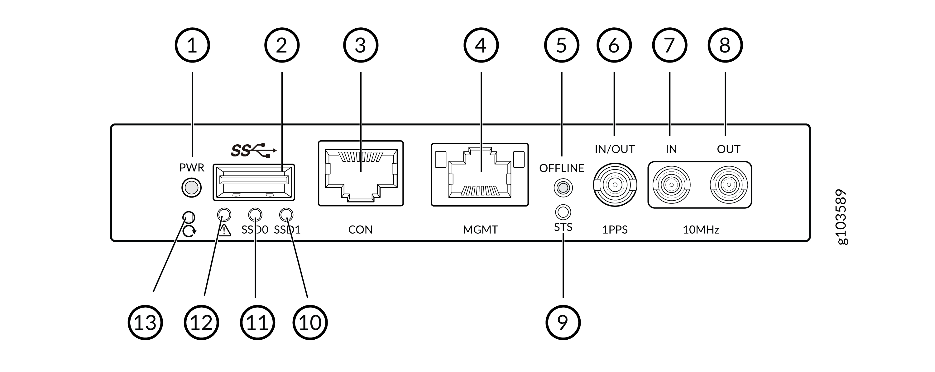
Component Type |
Callout |
Item |
Description |
|---|---|---|---|
|
Ports |
2 |
USB 3.0 interface |
USB port |
|
3 |
Console port |
Console port |
|
|
4 |
Management port |
RJ-45 Management port |
|
|
6 7 8 |
PTP ports |
Three DIN connectors on the front panel for external 10M IN, 10M OUT and PPS IN/OUT for PTP. |
|
|
Buttons |
5 |
Online/Offline |
Press the Online button momentarily causes the router to switch on. Pressing the Offline button continuously > 4 sec causes the router to power off. |
|
13 |
Reset |
Pressing this causes the switch to momentarily (~250ms) reset. Pressing for >10s will enter BIOS restore mode. |
|
|
LEDs |
1 |
Power (PWR) LED |
Indicates if the power supply board has a fault condition. |
|
9 |
STS LED |
Status LED. Indicates if the system is online. |
|
|
10 |
SSD1 LED |
Indicates if the second SSD is being accessed or not. |
|
|
11 |
SSD0 LED |
Indicates if the first SSD is being accessed or not. |
|
|
12 |
Alarm LED |
Indicates if the system has alarms |
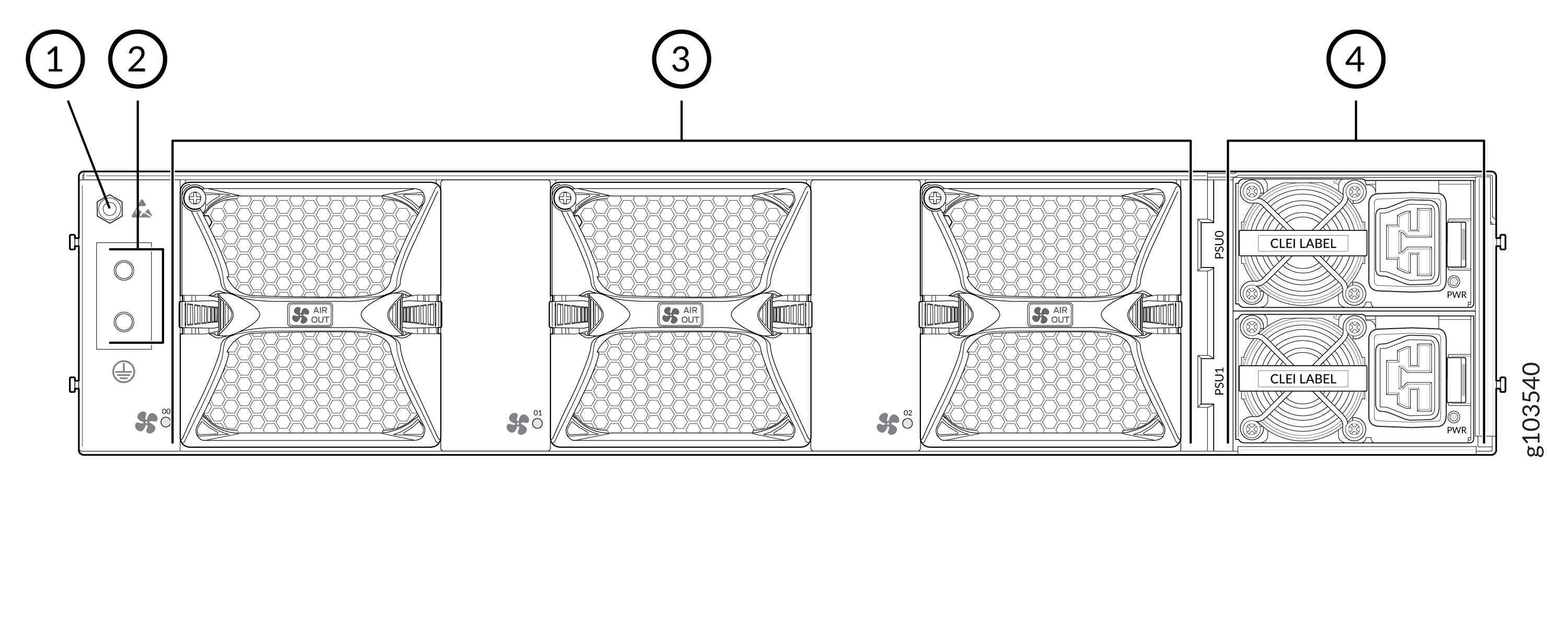
| Callout | Item | Description |
|---|---|---|
|
1 |
ESD point |
Electrostatic discharge (ESD) point |
|
2 |
Protective earthing terminal |
Protective earthing terminal |
|
3 |
Fan modules |
Fan modules |
|
4 |
PSUs |
Two PSUs |
PTX10002-60MR Power System and Cooling System
| Component | Slots | Shipped | Notes |
|---|---|---|---|
|
Power supplies |
2 |
One AC, 2200 W, 200-277 V, AC/HVAC/HVDC (190 V-410 V), AFO One DC, 2200 W, 48/60 V, AFO |
1 + 1 AC or 1 + 1 DC |
|
Fan modules |
3 |
3 fan modules |
3 fan modules each with 2 fans |