
PTX10002-60MR LEDs
This topic describes the status LEDs for the chassis and ports on the PTX10002-60MR.
The LEDs on the PTX10002-60MR indicate the status of the device and its components. You can also use the LEDs for troubleshooting.
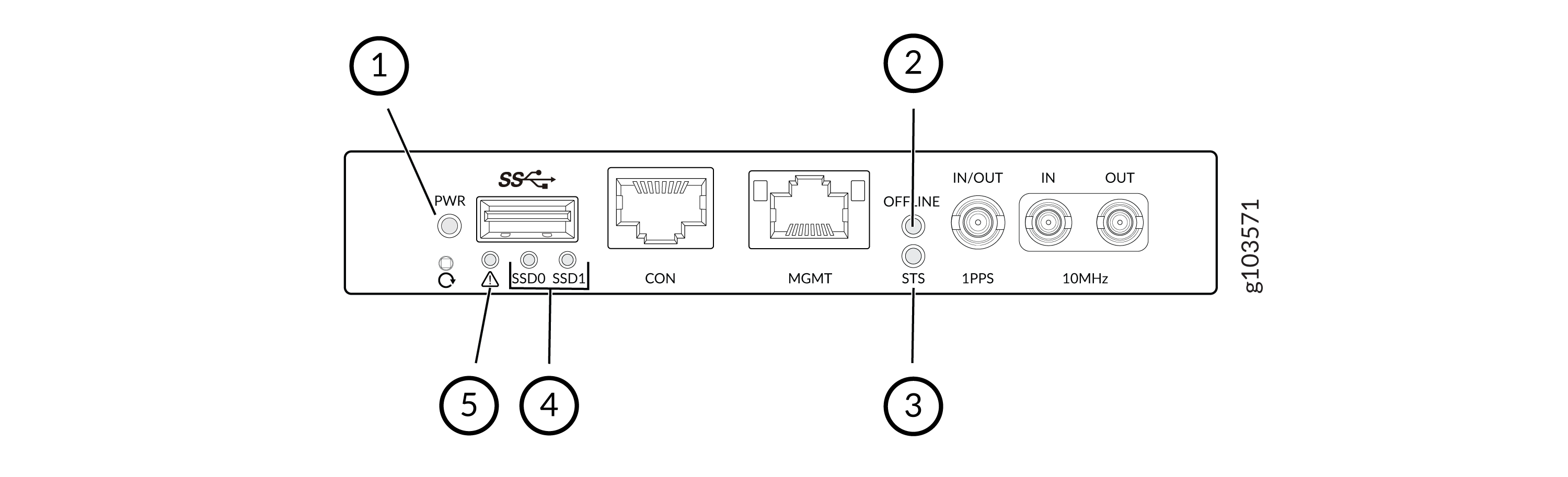
|
Callout |
Label/LED Type |
State |
Description |
|---|---|---|---|
|
1 |
PWR |
Green |
This LED indicates power status of the system. If there is power in the system, the LED glows Green. |
|
Red |
Indicates that there is no power in the system. |
||
|
2 |
Online/Offline |
Off |
System is offline |
|
Blipping green |
Default at power up |
||
|
Blinking Green |
System is loading software |
||
|
Green |
Software loaded |
||
|
3 |
STS |
Green |
Stands for Status LED. It indicates the operational state of the system. Steady Green color indicates that the system is online and functioning normally. |
|
Blinking red |
Indicates that the system has a fault condition |
||
|
4 |
SSD0 SSD1 |
Off |
SSD0 and/or SSD1 is not being accessed |
|
Blinking Green |
SSD0 and/or SSD1 storage device is being accessed |
||
|
5 |
Alarm |
Off |
No alarm |
|
Red |
Major alarm |
||
|
Yellow |
Minor alarm |
||
|
Yellow Blinking |
Both major and minor alarms are present |
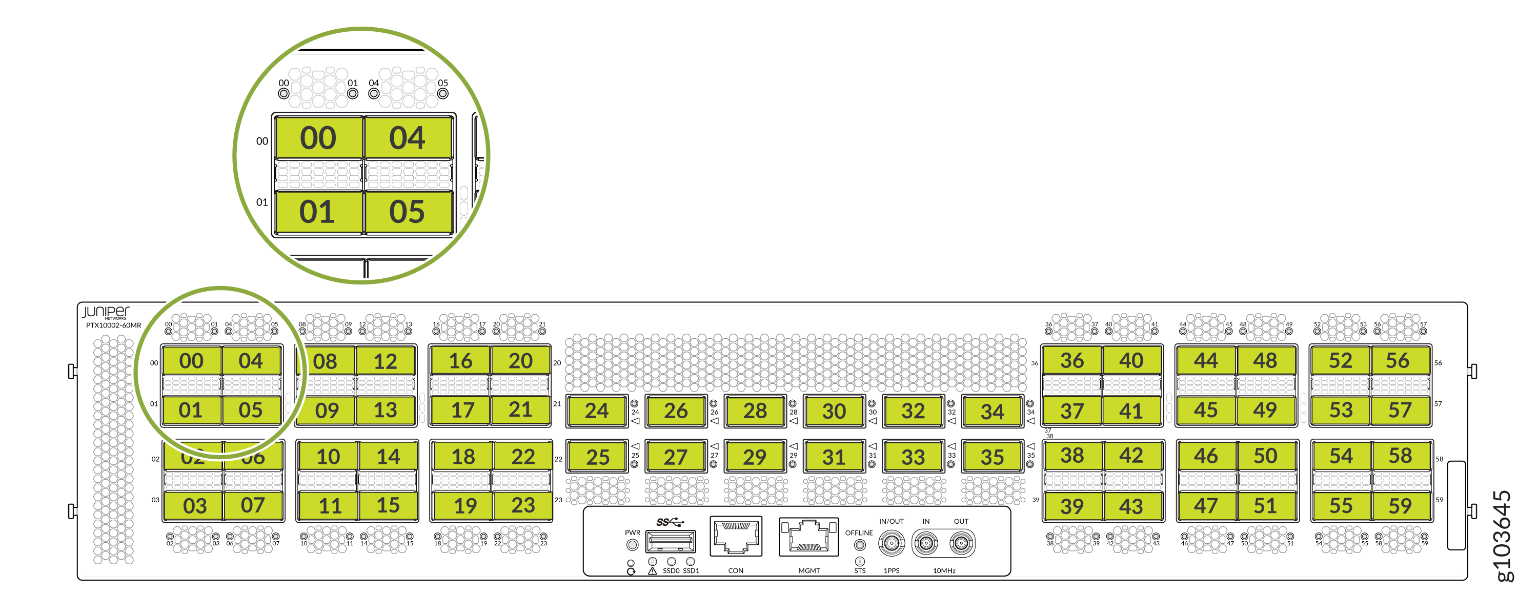
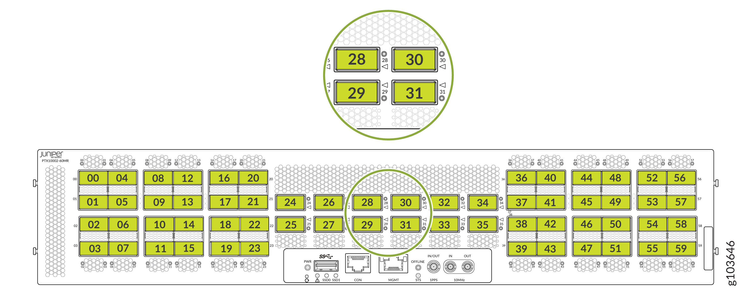
|
State |
Color |
Pattern |
Description |
|---|---|---|---|
|
On |
Green |
On steadily |
A link is established and all the channels are up. |
|
On |
Green |
Blinking |
The lane LED is indicating the fault in a port that is not receiving any signal. |
|
On |
Red |
On steadily |
The transceiver installed in the port has a failure. |
|
On |
Red |
Blinking |
The port is down; there is a failure in the transceiver hardware. |
|
On |
Amber |
On steadily |
The port has a fault (other than failure of the transceiver installed in it and the port not receiving any signal) and is not functioning normally. |
|
On |
Amber |
Blinking |
The port is down because of a failure other than in the transceiver hardware or the port is not receiving any signal. |
|
Off |
Unlit |
Unlit |
The port is not receiving any signal. |
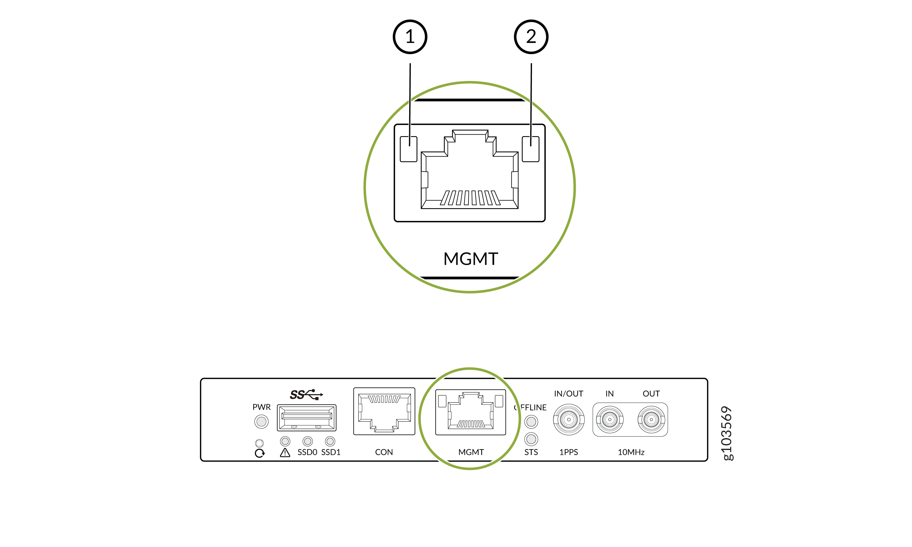
1 — Link Status LED | 2 — Activity LED |
|
LED |
LED Color |
Description |
|---|---|---|
|
Link status |
Off |
Link Down or Link up in 10M |
|
Yellow |
Link up in 100M |
|
|
Green |
Link up in 1G |
|
|
Activity LED |
Blinking Green |
Link is active |
|
Off |
Link is down |
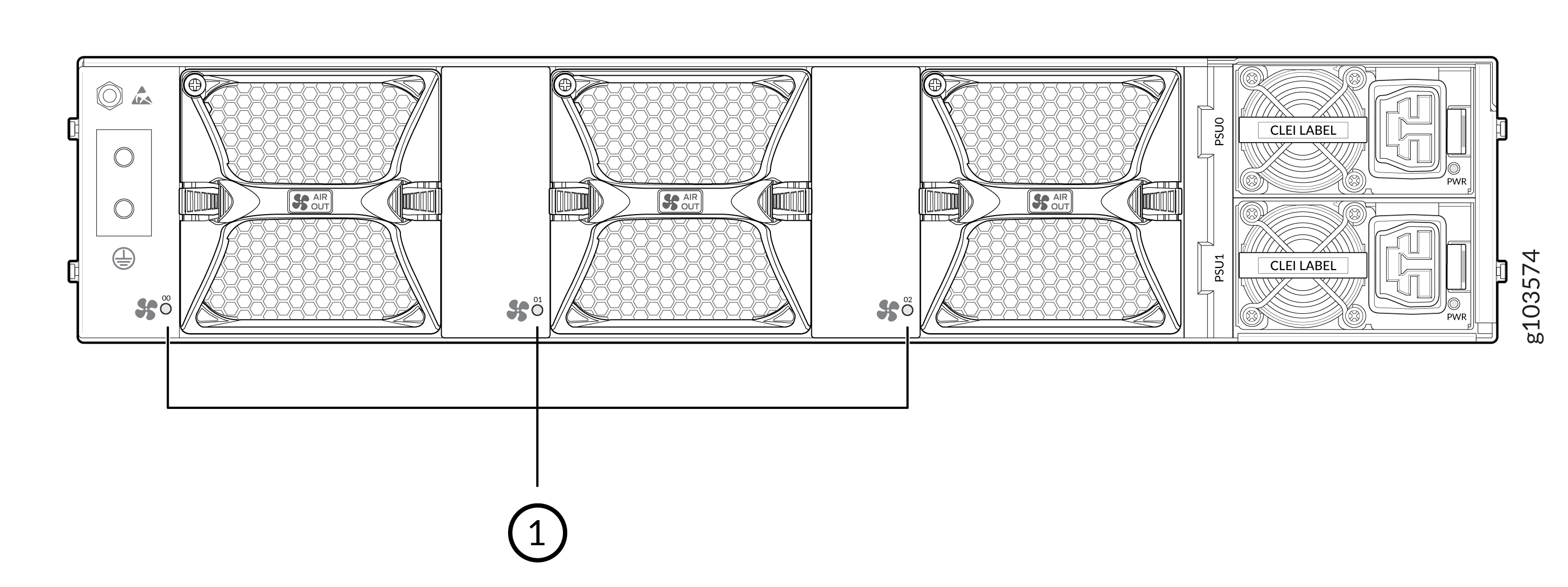
|
Callout |
Color |
Description |
|---|---|---|
|
1 |
Off |
Fan module is not present |
|
Blinking green |
Fan module software initialization is in progress. |
|
|
Green |
Fan initialization is complete and the fan is working normally. |
|
|
Amber |
Fan is faulty |

|
Callout |
Color |
Description |
|---|---|---|
|
1 |
Unlit |
PSU is off |
|
Green |
PSU is receiving power |
|
|
Amber |
PSU has a fault condition |