ON THIS PAGE
PTX10002-60MR Chassis
Learn about the components in the PTX10002-60MR chassis.
The PTX10002-60MR chassis is a rigid sheet-metal structure that houses all the device components.
PTX10002-60MR Physical Specifications
|
Description |
Weight |
Height |
Width |
Depth (Excluding Handle) |
|---|---|---|---|---|
|
Chassis |
~ 25 kgs |
88 mm |
445 mm |
564 mm |
| AC power supply units (PSUs) |
~ 1.5 kgs |
40.2 mm |
73.5 mm |
276 mm |
| DC PSUs |
~ 1.5 kgs |
40.2 mm |
73.5 mm |
276 mm |
|
Fan trays |
~ 0.6 kgs |
80 mm |
80 mm |
142.3 mm |
Install the routers only in restricted-access areas, such as dedicated equipment rooms and equipment closets, in accordance with Articles 110-16, 110-17, and 110-18 of the National Electrical Code, ANSI/NFPA 70.
Environmental Specifications
You must install the router in a rack or cabinet. You must house the router in a dry, clean, well-ventilated, and temperature-controlled environment.
Follow these environmental guidelines:
-
Keep the site as dust-free as possible, because dust can clog air intake vents and filters, reducing the efficiency of the router cooling system.
-
Maintain ambient airflow for normal router operation. If the airflow is blocked or restricted, or if the intake air is too warm, the router might overheat, leading to the router temperature monitor shutting down the device to protect the hardware components.
The following table provides the required environmental conditions for normal router operation.
|
Description |
Tolerance |
|---|---|
|
Altitude |
No performance degradation up to 6000 feet (1829 meters) |
|
Relative humidity |
Normal operation ensured in relative humidity range of 5% through 90%, noncondensing. |
|
Temperature |
|
|
Seismic |
Designed to comply with Zone 4 earthquake requirements according to NEBS GR DC 3160. |
General Site Guidelines
Efficient device operation requires proper site planning. For the device to operate properly, you must ensure maintenance and proper layout of the equipment, rack or cabinet, and wiring closet.
To plan and create an acceptable operating environment for your device and prevent environmentally caused equipment failures:
-
Keep the area around the chassis free from dust and conductive material, such as metal flakes.
-
Follow the prescribed airflow guidelines to ensure that the cooling system functions properly. Ensure that the exhaust from other equipment does not blow into the intake vents of the device.
-
Follow the prescribed electrostatic discharge (ESD) prevention procedures to prevent damaging the equipment. Static discharge can cause components to fail completely or intermittently over time.
-
Install the device in a secure area, so that only authorized personnel can access the device.
Site Electrical Wiring Guidelines
The following table describes the factors you must consider while planning the electrical wiring at your site.
You must provide a properly grounded and shielded environment and use electrical surge-suppression devices.
Avertissement Vous devez établir un environnement protégé et convenablement mis à la terre et utiliser des dispositifs de parasurtension.
|
Site Wiring Factor |
Guidelines |
|---|---|
|
Signaling limitations |
If your site experiences any of the following problems, consult experts in electrical surge suppression and shielding:
|
|
Radio frequency interference |
To reduce or eliminate RFI from your site wiring:
|
|
Electromagnetic compatibility |
If your site is susceptible to problems with electromagnetic compatibility (EMC), particularly from lightning or radio transmitters, seek expert advice. Strong sources of electromagnetic interference (EMI) can cause:
|
General Electrical Safety Guidelines and Warnings
Certain ports on the device are designed for use as intrabuilding (within-the-building) interfaces only (Type 2 or Type 4 ports as described in GR-1089-CORE) and require isolation from the exposed outside plant (OSP) cabling. To comply with NEBS (Network Equipment-Building System) requirements and protect against lightning surges and commercial power disturbances, the intrabuilding ports must not be metallically connected to interfaces that connect to the OSP or its wiring. The intrabuilding ports on the device are suitable for connection to intrabuilding or unexposed wiring or cabling only. The addition of primary protectors is not sufficient protection for connecting these interfaces metallically to OSP wiring.
Avertissement Certains ports de l’appareil sont destinés à un usage en intérieur uniquement (ports Type 2 ou Type 4 tels que décrits dans le document GR-1089-CORE) et doivent être isolés du câblage de l’installation extérieure exposée. Pour respecter les exigences NEBS et assurer une protection contre la foudre et les perturbations de tension secteur, les ports pour intérieur ne doivent pas être raccordés physiquement aux interfaces prévues pour la connexion à l’installation extérieure ou à son câblage. Les ports pour intérieur de l’appareil sont réservés au raccordement de câbles pour intérieur ou non exposés uniquement. L’ajout de protections ne constitue pas une précaution suffisante pour raccorder physiquement ces interfaces au câblage de l’installation extérieure.
Before removing or installing components of a device, connect an electrostatic discharge (ESD) grounding strap to an ESD point and wrap and fasten the other end of the strap around your bare wrist. Failure to use an ESD grounding strap could result in damage to the device.
Attention Avant de retirer ou d’installer des composants d’un appareil, raccordez un bracelet antistatique à un point de décharge électrostatique et fixez le bracelet à votre poignet nu. L’absence de port d’un bracelet antistatique pourrait provoquer des dégâts sur l’appareil.
Install the device in compliance with the following local, national, and international electrical codes:
-
United States—National Fire Protection Association (NFPA 70), United States National Electrical Code.
-
Other countries—International Electromechanical Commission (IEC) 60364, Part 1 through Part 7.
-
Evaluated to the TN power system.
-
Canada—Canadian Electrical Code, Part 1, CSA C22.1.
-
Suitable for installation in Information Technology Rooms in accordance with Article 645 of the National Electrical Code and NFPA 75.
Peut être installé dans des salles de matériel de traitement de l’information conformément à l’article 645 du National Electrical Code et à la NFPA 75.
-
Locate the emergency power-off switch for the room in which you are working so that if an electrical accident occurs, you can quickly turn off the power.
-
Ensure that you clean grounding surface and give them a bright finish before making grounding connections.
-
Do not work alone if potentially hazardous conditions exist anywhere in your workspace.
-
Never assume that power is disconnected from a circuit. Always check the circuit before starting to work.
-
Carefully look for possible hazards in your work area, such as moist floors, ungrounded power extension cords, and missing safety grounds.
-
Operate the device within marked electrical ratings and product usage instructions.
-
To ensure that the device and peripheral equipment function safely and correctly, use the cables and connectors specified for the attached peripheral equipment, and make certain they are in good condition.
You can remove and replace many device components without powering off or disconnecting power to the device, as detailed elsewhere in the hardware documentation for this device. Never install equipment that appears to be damaged.
Rack Requirements
You can mount the device on two-post racks or four-post racks.
|
Rack Requirement |
Guidelines |
|---|---|
|
Rack Type |
A U is the standard rack unit defined by the Electronic Components Industry Association (ECIA) (http://www.ecianow.org). You can mount the device on a rack that provides bracket holes or hole patterns spaced at 1-U (1.75 in. or 4.45 cm) increments and meets the size and strength requirements to support the weight. |
|
Mounting bracket hole spacing |
The holes in the mounting brackets are spaced at 1-U (1.75 in. or 4.45 cm) so that the device can be mounted in any rack that provides holes spaced at that distance. |
|
Rack size and strength |
Ensure that the:
|
|
Rack connection to building structure |
|
Cabinet Requirements
You can mount the device in a cabinet that contains a 19-in. rack.
PTX10002-60MR supports closed racks (cabinets) and open racks (2-post/4-post).
|
Cabinet Requirements |
Guidelines |
|---|---|
|
Cabinet size and clearance |
|
|
Cabinet airflow requirements |
When you mount the device in a cabinet:
|
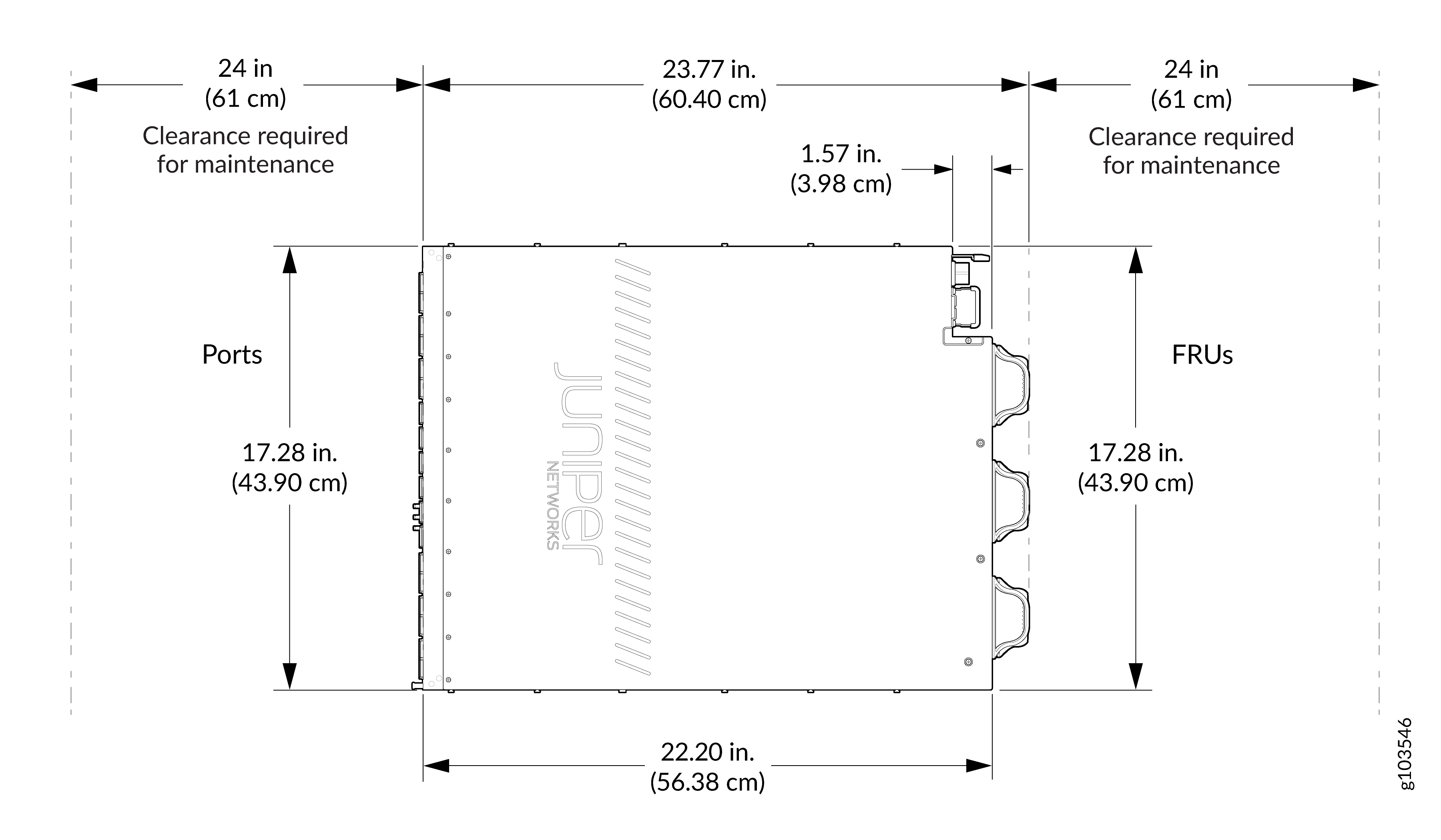
Clearance Requirements for Airflow and Hardware Maintenance for PTX10002-60MR Routers
When planning the site for installing a PTX10002-60MR Router, follow these clearance requirements:
-
For the cooling system to function properly, ensure that the airflow around the chassis is unrestricted.
-
If you are mounting the router on a rack or cabinet along with other equipment, ensure that the hot air exhaust from other equipment does not blow into the cold air intake vents of the chassis.
-
Allow at least 30 in. (76.2 cm) in front of the rack or cabinet and 24 in. (61 cm) behind the rack or cabinet.
-
Leave at least 24 in. (61 cm) clearance in front of and behind the router for service personnel to remove and install hardware components.