PTX10002-36QDD Rear Panel
The rear panel houses the power supply units (PSUs), fan modules, a BITS port, 10-MHz ports, pulse per second (PPS) ports, and a protective earthing terminal.
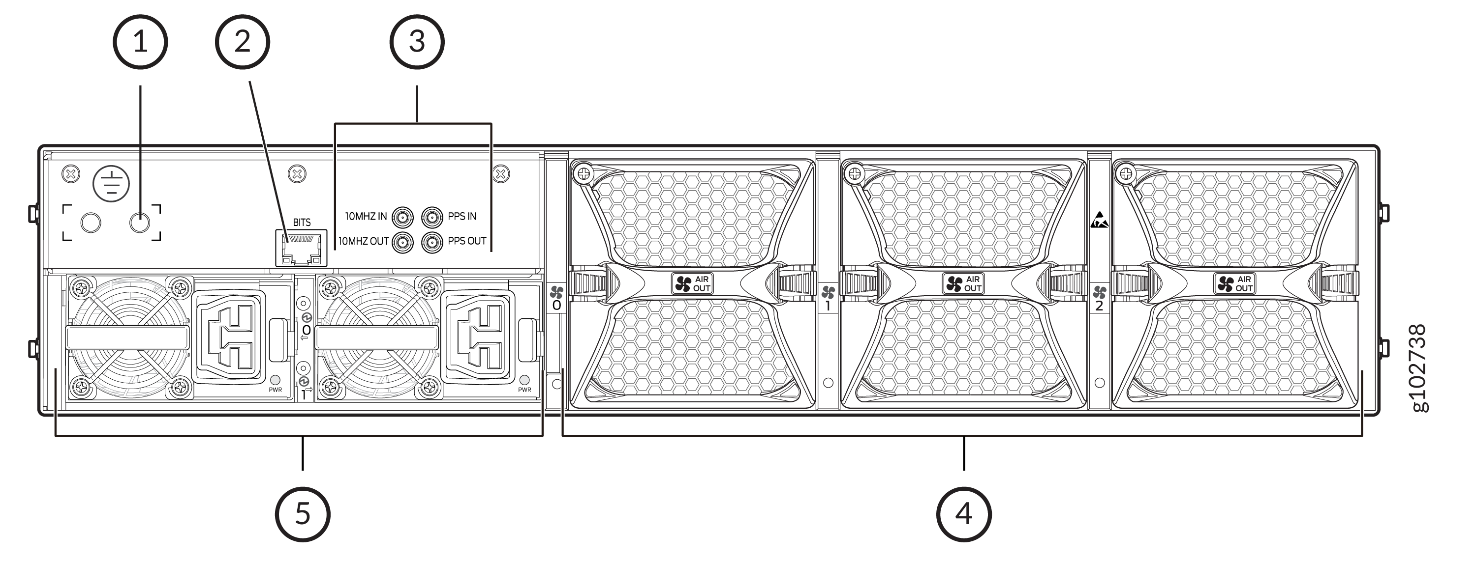
1 — Protective earthing terminal | 4 — Fan modules |
2 — BITS port | 5 — Power supply units |
3 — 10-MHz and PPS ports |
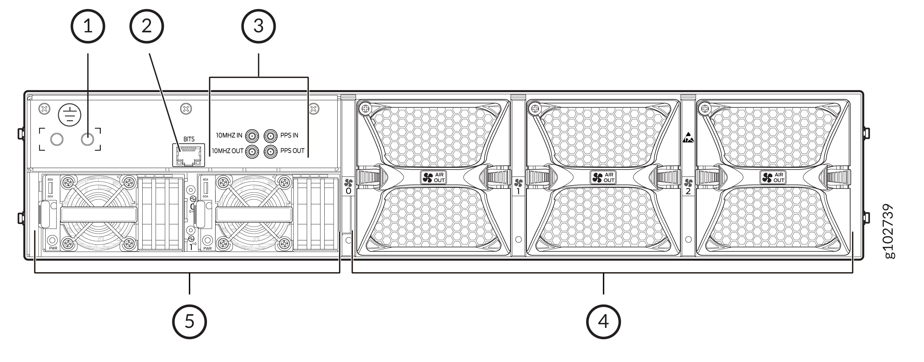
1 — Protective earthing terminal | 4 — Fan modules |
2 — BITS port | 5 — Power supply units |
3 — 10-MHz and PPS ports |
The 10-MHz and PPS input clock connectors are used to connect to an external clock source, such as a GNSS receiver with precise timing outputs. The 10-MHz and PPS outputs provide debug information for the Synchronous Ethernet and IEEE 1588 timing circuitry.
The LEDs on the BITS port are used to convey the status of the T1/E1 BITS timing interface. Table 1 describes BITS LEDs.
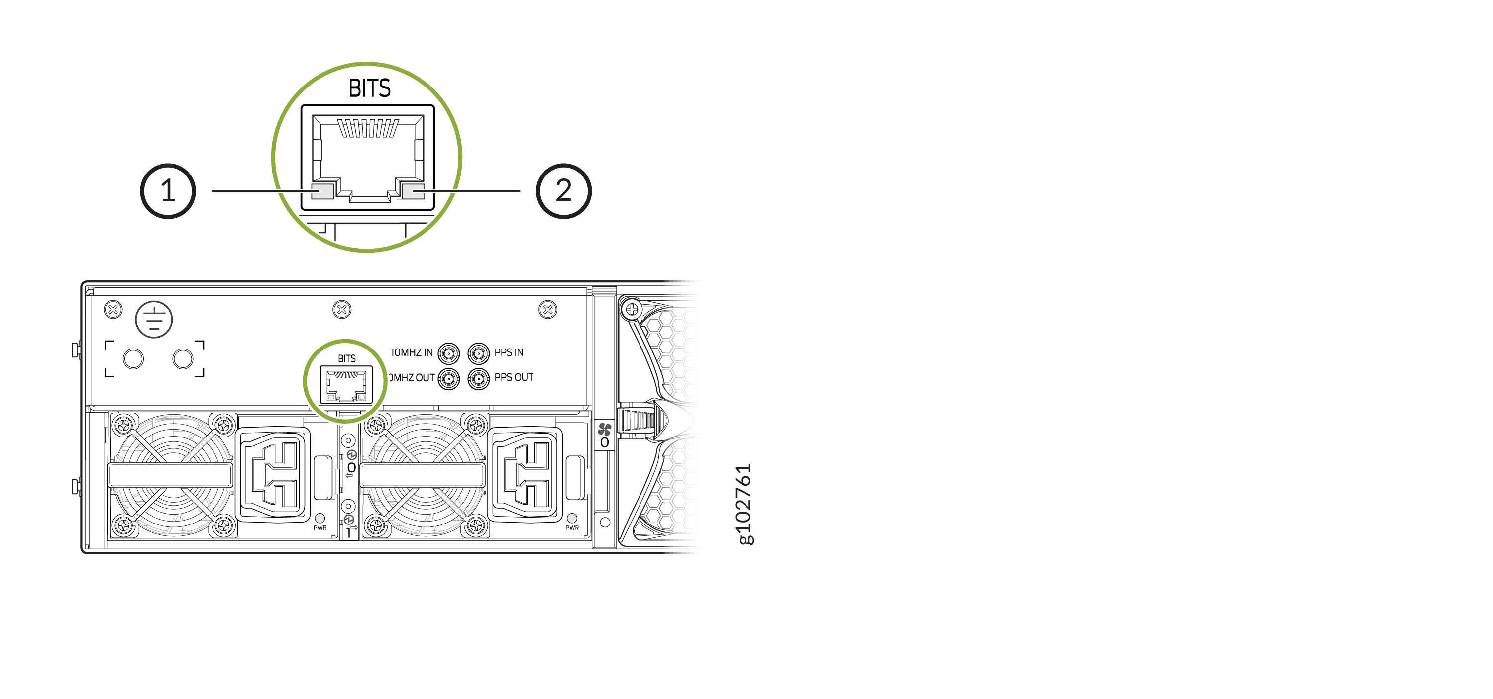
1 — Error LED | 2 — Link LED |
|
LED |
State |
Color |
Pattern |
Description |
|---|---|---|---|---|
|
Link LED |
On |
Green |
On steadily |
The link is active. |
|
Link LED |
Off |
— |
— |
The link is not active. |
|
Error LED |
On |
Amber |
Blinking |
There is an error. |