PTX10002-36QDD Management Panel
The management panel in the router is on the far right side of the front panel, above the port LEDs.
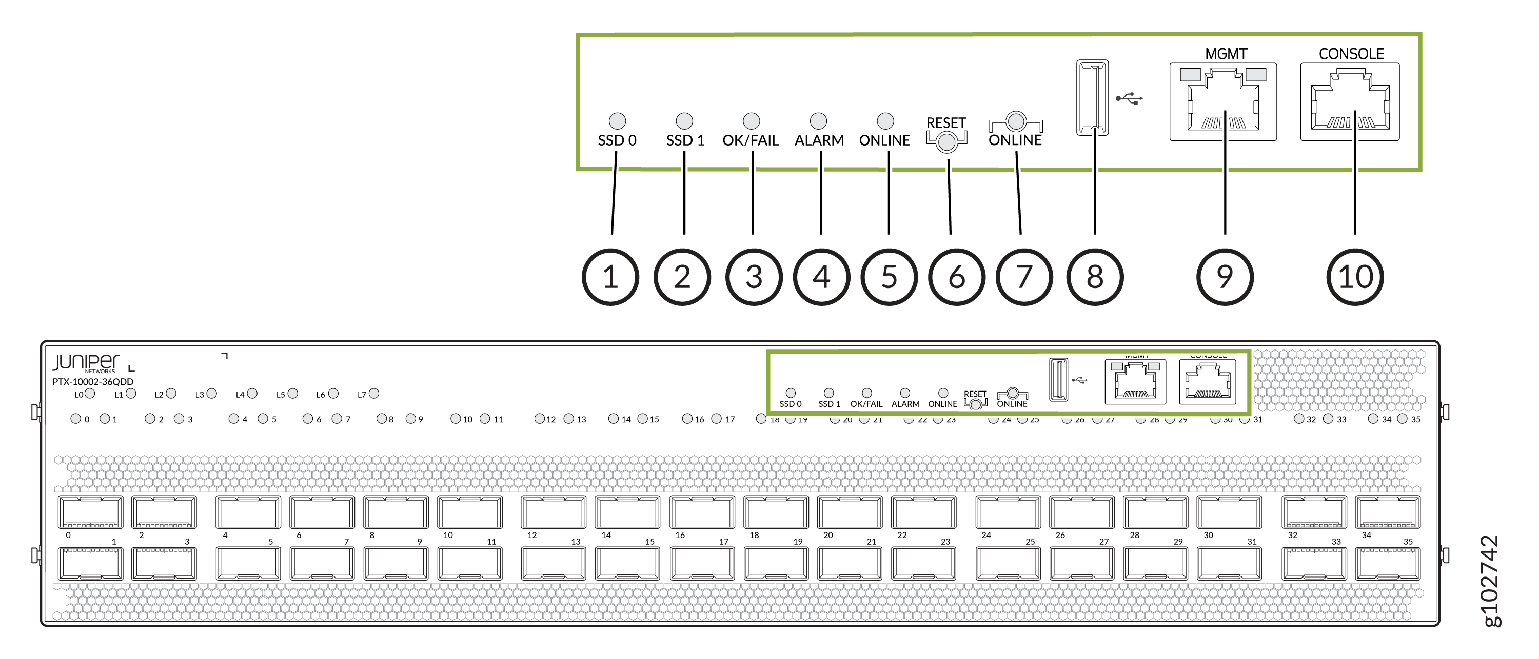
1 — SSD 0 LED | 6 — Reset button |
2 — SSD 1 LED | 7 — Online button |
3 — OK/FAIL LED | 8 — Management port with a Type A USB connector |
4 — Alarm LED | 9 — Management port with an RJ-45 connector |
5 — Online LED | 10 — Console port with an RJ-45 connector |
If you press the Reset button once, the router resets. If you press the Reset button for more than 10 seconds, the router enters the BIOS restore mode.
If you press the Online button for more than four seconds, all the power rails except the BIAS 3V3, which powers RE FPGA, power off. If you press it once more, the power-on sequence starts.
Table 1 describes the OK/FAIL LED.
|
State |
Color |
Pattern |
Description |
|---|---|---|---|
|
On |
Green |
On steadily |
The router does not have any fault and is functioning normally. |
|
On |
Red |
Blinking |
The router has a fault and is not functioning normally. |
Table 2 describes the Alarm LED.
|
State |
Color |
Pattern |
Description |
|---|---|---|---|
|
On |
Red |
On steadily |
There is a major alarm. |
|
On |
Yellow |
On steadily |
There is a minor alarm. |
|
On |
Yellow |
Blinking |
There is a major alarm and a minor alarm. |
|
Off |
— |
— |
There is no alarm. |
Figure 1 shows the LEDs on the management port. Table 3 describes the LEDs on the management port with an RJ-45 connector.
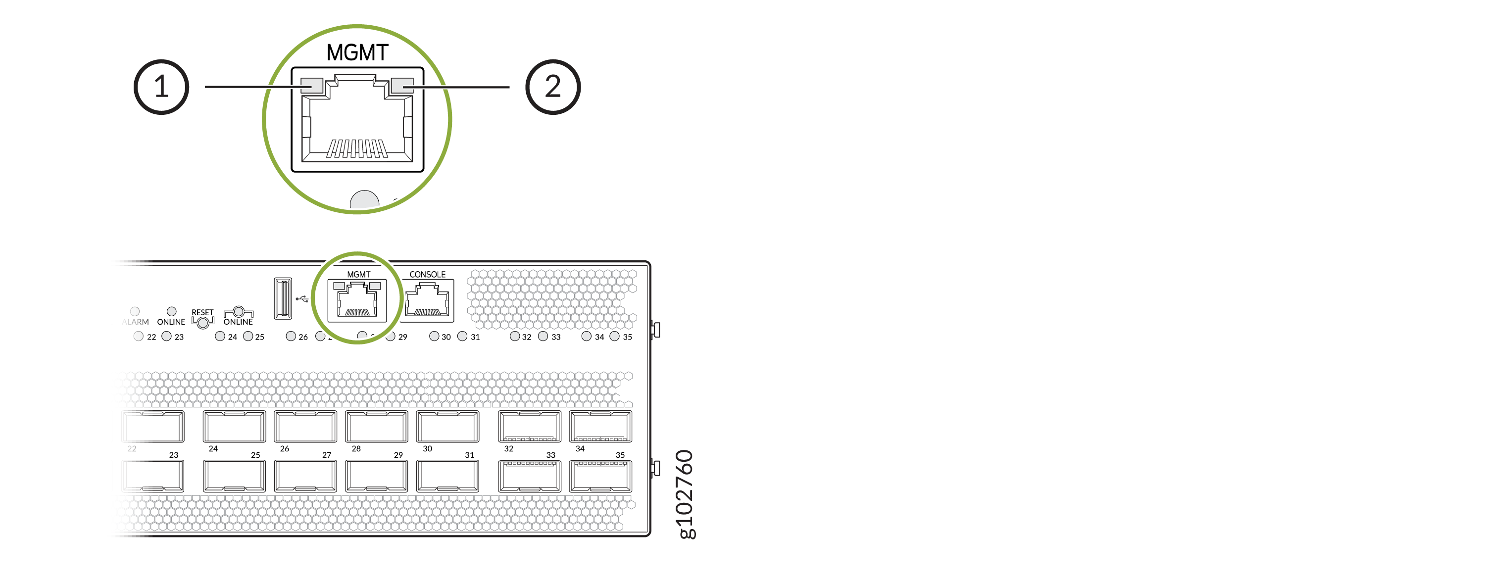
1 — Link activity LED | 2 — Speed status LED |
|
LED |
State |
Color |
Pattern |
Description |
|---|---|---|---|---|
|
Link activity LED |
On |
Green |
Blinking |
The port and the link are active, and there is link activity. |
|
Speed status LED |
On |
Green |
On steadily |
The link speed is 1000 Mbps. |
|
Speed status LED |
On |
Yellow |
On steadily |
The link speed is 100 Mbps. |
|
Speed status LED |
Off |
— |
— |
The link speed is 10 Mbps or the link is not active. |
Table 4 describes the SSD LEDs.
|
State |
Color |
Pattern |
Description |
|---|---|---|---|
|
On |
Green |
Blinking |
The corresponding SSD storage device is being accessed. |
|
Off |
— |
— |
The corresponding SSD is not being accessed. |
Table 5 describes the Online LED.
|
State |
Color |
Pattern |
Description |
|---|---|---|---|
|
On |
Green |
On steadily |
The software in the router is booted. |
|
On |
Green |
Blinking |
The software in the router is booting up. |
|
On |
Green |
Blipping |
The router is powering up. |
|
Off |
— |
— |
The router is offline. |