NFX350 Interface Modules
LTE on NFX350 Devices
- Overview
- Features Supported on the LTE Module for NFX Devices
- Understanding the LTE Physical Interface
- Understanding the LTE Logical Interface
Overview
The LTE module operates on both 3G and 4G networks and provides wireless WAN support on the NFX350 devices. The NFX350 portfolio consists of models with or without LTE support. provides a summary of the models that support LTE.
Model |
Mode |
Operating Region |
Frequency Band |
|---|---|---|---|
|
|
|
For LTE:
For 3G (HSPA+):
|
|
|
|
For LTE:
For 3G (HSPA+):
|
Features Supported on the LTE Module for NFX Devices
The LTE module supports the following features:
Automatic switchover between service providers through dual SIMs—The module supports up to two Subscriber Identity Module (SIM) cards. Dual SIM cards allow connectivity to two different ISP networks and provide a failover mechanism when the current active network fails. Each SIM card is associated with a profile, which is used to connect to the network.
Multiple service provider and access point name (APN) profiles—You can configure up to 16 profiles for each SIM, although only one profile can be active at a time. The LTE module supports two SIM cards and so you can configure a total of 32 profiles.
LTE carrier aggregation—Carrier aggregation expands the LTE bandwidth by combining secondary bands, which results in increased capacity and network efficiency.
SIM security functions—The module supports security functions such as SIM lock and unlock, and PIN change.
Always-on, dial-on-demand, and backup modes—The Mini-PIM can be configured in three modes:
Always-on—The LTE module connects to the 3G/4G network after booting. The connection is always maintained, as long as there are no network or connectivity problems.
Dial-on-demand—The Mini-PIM initiates a connection when it receives interesting traffic. You define interesting traffic using the dialer filter. To configure dial-on-demand using a dialer filter, you first configure the dialer filter and then apply the filter to the dialer interface.
Note:The dial-on-demand mode is supported only if the LTE module is configured as a primary interface.
Backup—The module connects to the 3G/4G network when the primary connection fails.
Primary and backup interface—You can configure the LTE module either as a primary interface or as a backup interface.
When configured as the primary interface, the LTE module supports both the Always-on and Dial-on-demand modes.
When configured as the backup interface, the LTE module connects to the network only when the primary interface fails.
Over-the-air upgrade for modem firmware—Over-the-air (OTA) firmware upgrade enables automatic and timely upgrade of modem firmware when new firmware versions are available. The OTA upgrade can be enabled or disabled on the LTE module.
Note:OTA upgrade is disabled by default.
Understanding the LTE Physical Interface
The physical interface for the LTE module uses the name cl-1/1/0. You configure the following properties on the physical interface:
A dialer pool to which the physical interface belongs and the priority of the interface in the pool.
Profiles for the SIM cards.
Radio access technology (automatic, 3G, LTE)
Understanding the LTE Logical Interface
The dialer interface, dl0, is a logical interface, which is used to trigger calls. When traffic is sent to the dl0 interface, it enables the physical interface in the dialer pool and places calls through the physical interface. The dialer interface can perform backup and dialer filter functions. You can configure the dialer interface to operate in any one of the following ways:
Primary interface—The dialer interface connects to the network and is always on.
Backup interface for the primary WAN connection—The dialer interface is activated only when the primary connection fails.
Dial-on-demand—The dialer interface activates the connection to the wireless network only when it receives interesting traffic.
The following rules apply when you configure dialer interfaces:
You cannot configure the dialer interface as a constituent link in a multilink bundle.
You cannot configure any dial-in options for the dialer interface.
You configure the following for a dialer interface:
A dialer pool to which the physical interface belongs.
Dial string (destination number to be dialed).
You can also specify optional operating parameters for the dialer interface:
Activation delay—Number of seconds after the primary interface is down before the backup interface is activated. The default value is 0 seconds, and the maximum value is 60 seconds.
Deactivation delay—Number of seconds after the primary interface is up before the backup interface is deactivated. The default value is 0 seconds, and the maximum value is 60 seconds.
LTE Expansion Module (NFX-LTE-AE and NFX-LTE-AA)
Figure 1 shows the front panel components of the LTE expansion module.
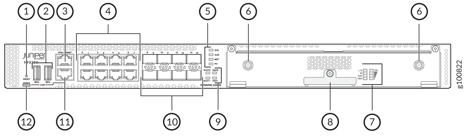
1 — Mini USB console port | 7 — SIM card signal strength and status of the network connection |
2 — RJ-45 console port | 8 — SIM card cover |
3 — One 10/100/1000BASE-T RJ-45 management port | 9 — Two 1-Gigabit Ethernet/10-Gigabit Ethernet SFP+ WAN ports |
4 — Four 10/100/1000BASE-T RJ-45 LAN ports | 10 — USB 3.0 port |
5 — System status LEDs | 11 — Reset button |
6 — Antenna slot |
Table 2 lists the components on the front panel of the LTE expansion module.
|
Component |
Description |
|---|---|
|
Antenna connectors |
Two SubMiniature version A (SMA) connectors. |
|
SIM slots |
Two slots, SIM1 and SIM2, for inserting the SIM cards. The LTE Mini-PIM supports standard, micro, and nano SIMs. The standard SIM can be inserted directly in the SIM slot. To insert micro and nano SIMs, use the SIM adapters supplied with the Mini-PIM. The Mini-PIM is shipped with two SIM adapters. |
|
LEDs |
Indicate the status at a glance. |
The LTE expansion module supports two multi-band swivel-mount dipole antennas, which can be rotated 360°. You can rotate the antennas and select the angle at which the signal strength is high. Table 3 lists the specifications for the antenna.
|
Specification |
Value |
|---|---|
|
Part number |
640-077768 |
|
Operating frequency range |
|
|
Voltage Standing Wave Ratio (VSWR) |
<=2.8 |
|
Impedance |
50 Ohms |
|
Radiation |
Omnidirectional |
|
Gain |
1-4 dBi |
|
Polarization |
Vertical |
|
Connector type |
SMA |
|
Length |
120 mm |
The antenna is connected to the NFX350 device through the magnetic antenna base. Table 4 lists the specifications for the antenna base.
|
Specification |
Value |
|---|---|
|
Part number |
640-077767 |
|
Cable length |
3 m |
|
Connector type |
SMA |
|
Dimensions (H x W x L) |
29.50 mm x 73 mm x 73 mm |
Table 5 provides the hardware specifications for the LTE expansion module.
|
Description |
Value |
|---|---|
|
Dimensions (W x D x H) |
8.40 in x 5.20 in x 1.45 in |
|
Weight |
368 grams |
|
Connector Type |
Golden Finger |
|
Environmental Operating Temperature |
32° to 104° F (0° to 40° C) |
|
Storage Temperature |
- 40°F to 158° F (-40° to 70° C) |
|
Relative Humidity |
(Operating) 5 to 90% non-condensing |