NFX350 Chassis
Front Panel of an NFX350 Device
Figure 1 shows the front panel components of an NFX350 device.
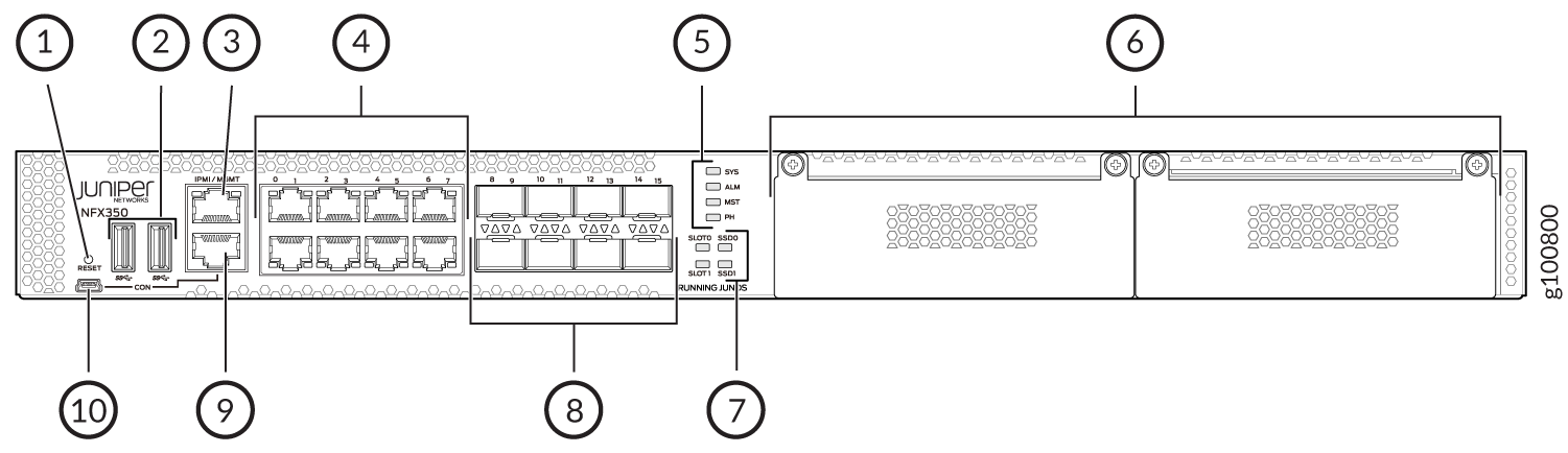
1 — Reset button | 6 — Two expansion slots |
2 — Two USB 3.0 ports | 7 — SSD and slot status LEDs |
3 — One 10/100/ 1000BASE-T RJ-45 management port | 8 — Eight 1-Gigabit Ethernet/10-Gigabit Ethernet SFP+ WAN ports |
4 — Eight 10/100/ 1000BASE-T RJ-45 LAN ports | 9 — RJ-45 console port |
5 — System status LEDs | 10 — Mini-USB console port |
Rear Panel of an NFX350 Device
Figure 2 shows the rear panel of the NFX350 device. The rear panel of the NFX350 device consists of the following components:
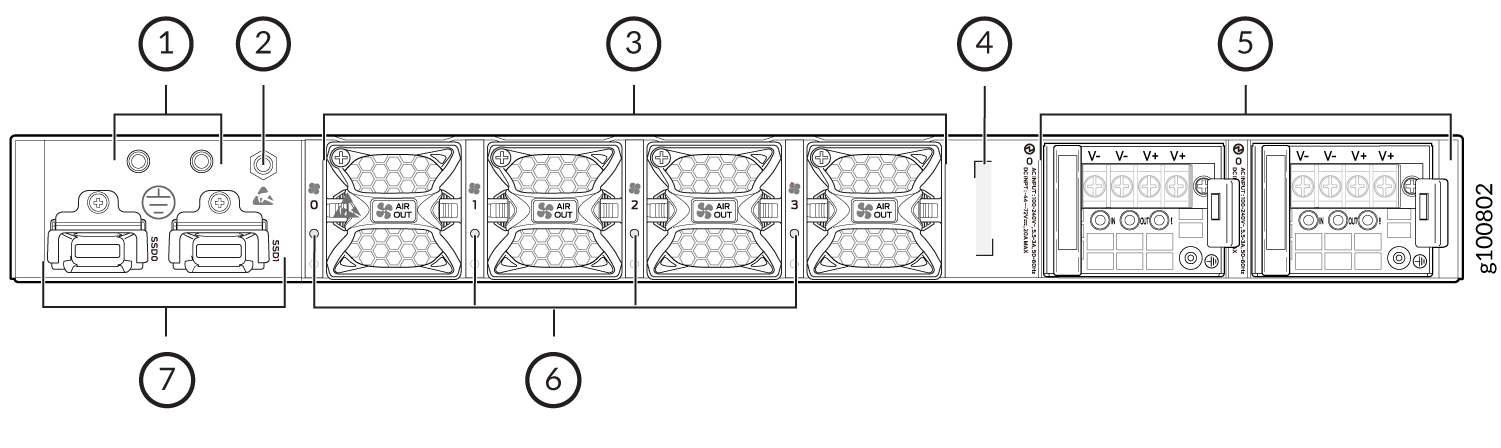
1 — Grounding point | 5 — Two power supply units |
2 — Electrostatic discharge (ESD) point | 6 — Fan status LEDs |
3 — Four fans | 7 — Two SSD trays |
4 — CLEI code |
LED Details of an NFX350 Device
Chassis Status LEDs
The front panel of an NFX350 device has chassis status LEDs labeled ALM, SYS, MST and PH.
Figure 3 shows the chassis status LEDs in an NFX350 device.
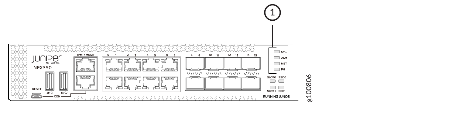
1 — Chassis status LEDs (ALM, SYS, MST, and PH) |
Table 1 describes
the chassis status LEDs in an NFX350 device, their colors and states,
and the status they indicate. You can view the colors of the four
LEDs remotely through the CLI by issuing the operational mode command show chassis led.
|
LED Label |
Color |
State and Description |
|---|---|---|
|
ALM |
Red |
There is a major alarm. |
|
Amber |
There is a minor alarm. |
|
|
Off |
There is no alarm or the device is halted. |
|
|
SYS |
Green solid (On) |
Junos OS has been loaded on the device. |
|
Green blinking |
The device is booting. |
|
|
Off |
The device is powered off or is halted. |
|
|
MST |
Green solid (On) |
The device is functioning normally. |
|
Off |
The device is powered off or is halted. |
|
|
Phone Home |
Green solid (On) |
Phone Home is terminated successfully. |
|
Green blinking |
Phone Home is in progress. |
|
|
Amber solid |
Phone Home is terminated unsuccessfully. |
|
|
Amber blinking |
Phone Home is waiting for user input. |
|
|
Off |
There is no Phone Home transaction. |
A major alarm (red) indicates a critical error condition that requires immediate action.
A minor alarm (amber) indicates a noncritical condition that requires monitoring or maintenance. A minor alarm left unchecked might cause interruption in service or performance degradation.
All four LEDs can be lit simultaneously.
Network Port and Uplink Port LEDs
Each network port and uplink port on the front panel of an NFX350 has two LEDs that indicate link activity and port status (see Figure 4).
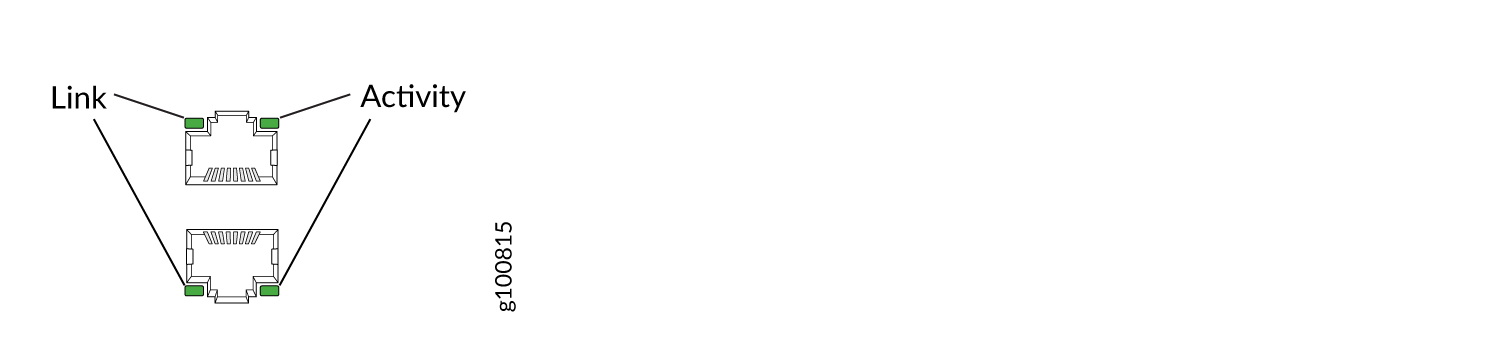
Table 2 describes the Link and Activity LED.
|
LED |
Color |
State and Description |
|---|---|---|
|
Link |
Green solid (On) |
The link is up. |
|
Off |
The link is down. |
|
|
Activity |
Green blinking |
The link is up and there is traffic on the port. |
|
Green solid (On) |
The link is up and but there is no traffic on the port. |
|
|
Off |
The link is down. |
Management Port LEDs
The management port on the front panel of an NFX350 device has two LEDs that indicate link activity and port status.
Table 3 describes the Link/Activity LED.
|
LED |
Color |
State and Description |
|---|---|---|
|
Link |
Green solid (On) |
The link is up. |
|
Off |
The link is down. |
|
|
Activity |
Green blinking |
There is traffic on this port. |
|
Off |
There is no traffic on this port. |
Table 4 describes the SSD LED.
|
LED |
Color |
State and Description |
|---|---|---|
|
SSD |
Green solid (On) |
SSD is active, but not accessed. |
|
Green blinking |
SSD is active and is accessed. |
|
|
Amber solid |
SSD locate bit is set. |
|
|
Amber blinking |
SSD has some issues. |
|
|
Off |
SSD is not present. |
Table 5 describes the slot LED.
|
LED |
Color |
State and Description |
|---|---|---|
|
Slot |
Green solid (On) |
Module initial process is successful. |
|
Amber solid |
Module initial process failed |
|
|
Off |
Module is not present. |
If NFX-LTE-AA or NFX-LTE-AE module (two slot width expansion module) is inserted, expansion module status is shown by slot LED0.
LTE Module LEDs
Table 6 lists the LEDs on the LTE module and their indications.
|
LED |
Color |
Description |
|---|---|---|
|
SIG (Received Signal Strength indicator) |
Solid green (One bar) |
Low signal strength (<= -99dBm) |
|
Solid green (Two bars) |
Low signal strength (from -98dBm to -87dBm) |
|
|
Solid green (Three bars) |
Low signal strength (from -86dBm to -76dBm) |
|
|
Solid green (Four bars) |
High signal strength (>=-75dBm) |
|
|
Off |
No signal |
|
|
3G |
Solid green |
3G connection is established |
|
Blinking green |
Connection to a 3G network |
|
|
LTE |
Solid green |
LTE connection is established |
|
Blinking green |
Connection to a LTE network |
|
|
SIM1 |
Solid green |
SIM1 is active |
|
SIM2 |
Solid green |
SIM2 is active |
If all the LEDs are blinking, it indicates that firmware updates are in progress. Do not power off the device before the updates complete.