MX960 Extended Cable Manager Installation Instructions
This topic describes how to install the extended cable manager on a Juniper Networks MX960 Universal Routing Platform.
This installation procedure requires you to power down the router.
Read this document completely before you install the extended cable manager.
Extended Cable Manager Description
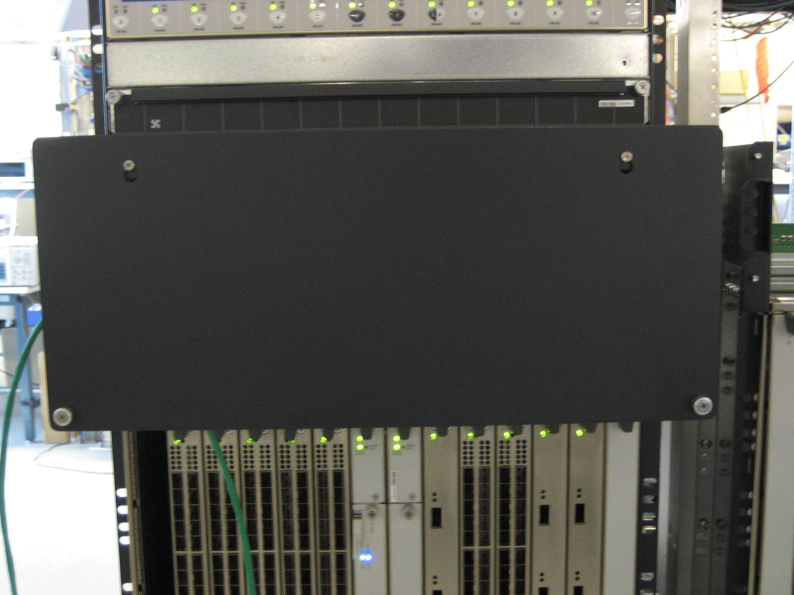
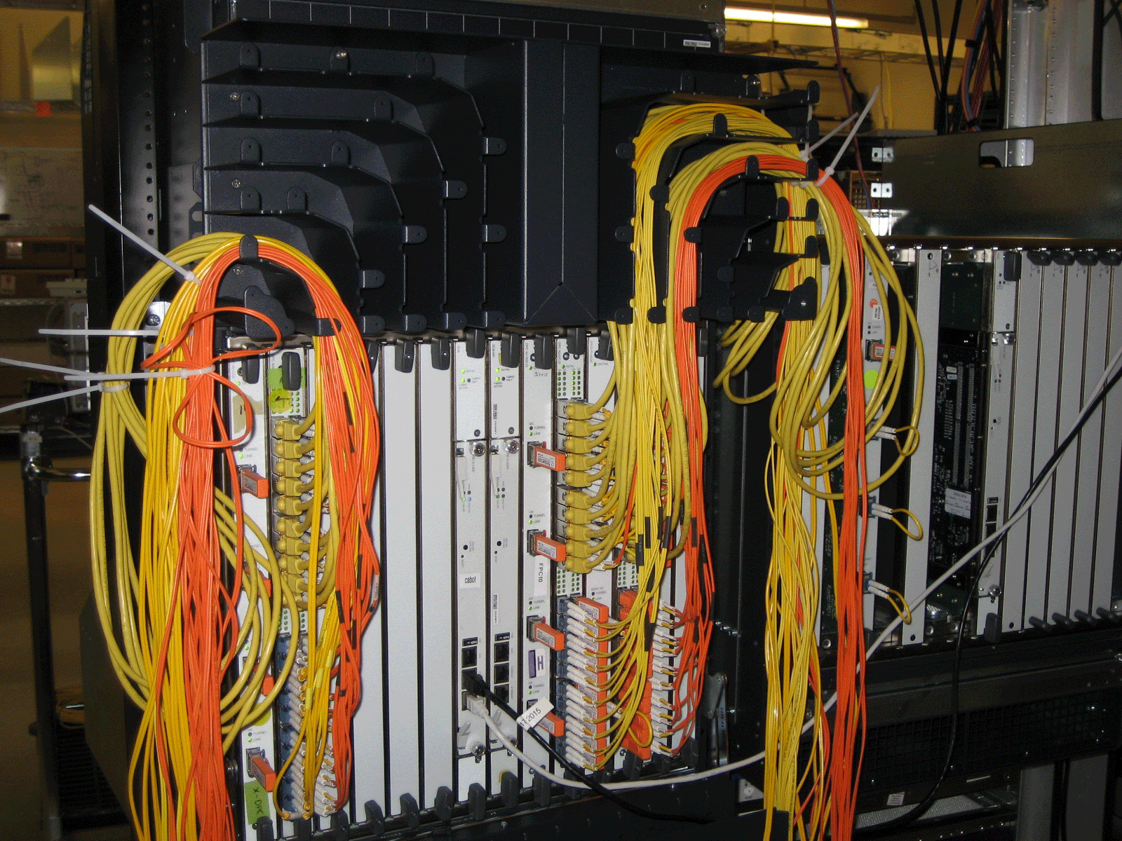
The extended cable manager allows you to manage a large number of fiber-optic and copper cables attached to the Dense Port Concentrators (DPCs) installed in the router. It is installed in the top of the MX960 chassis.
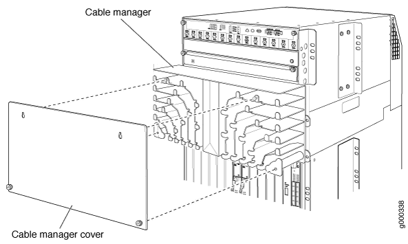
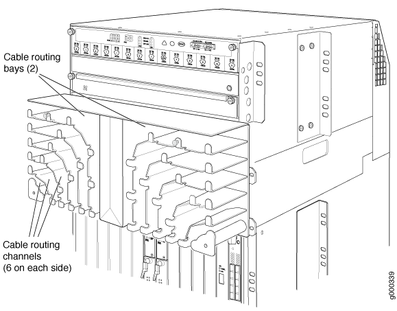
The extended cable manager consists of the following parts (see Figure 1 and Figure 2):
-
Top hat assembly—A sheet metal assembly that contains the cable routing channels and cable routing bay cover, the front panel ribbon cable, and the double-sided electrical connector for the upper fan tray.
-
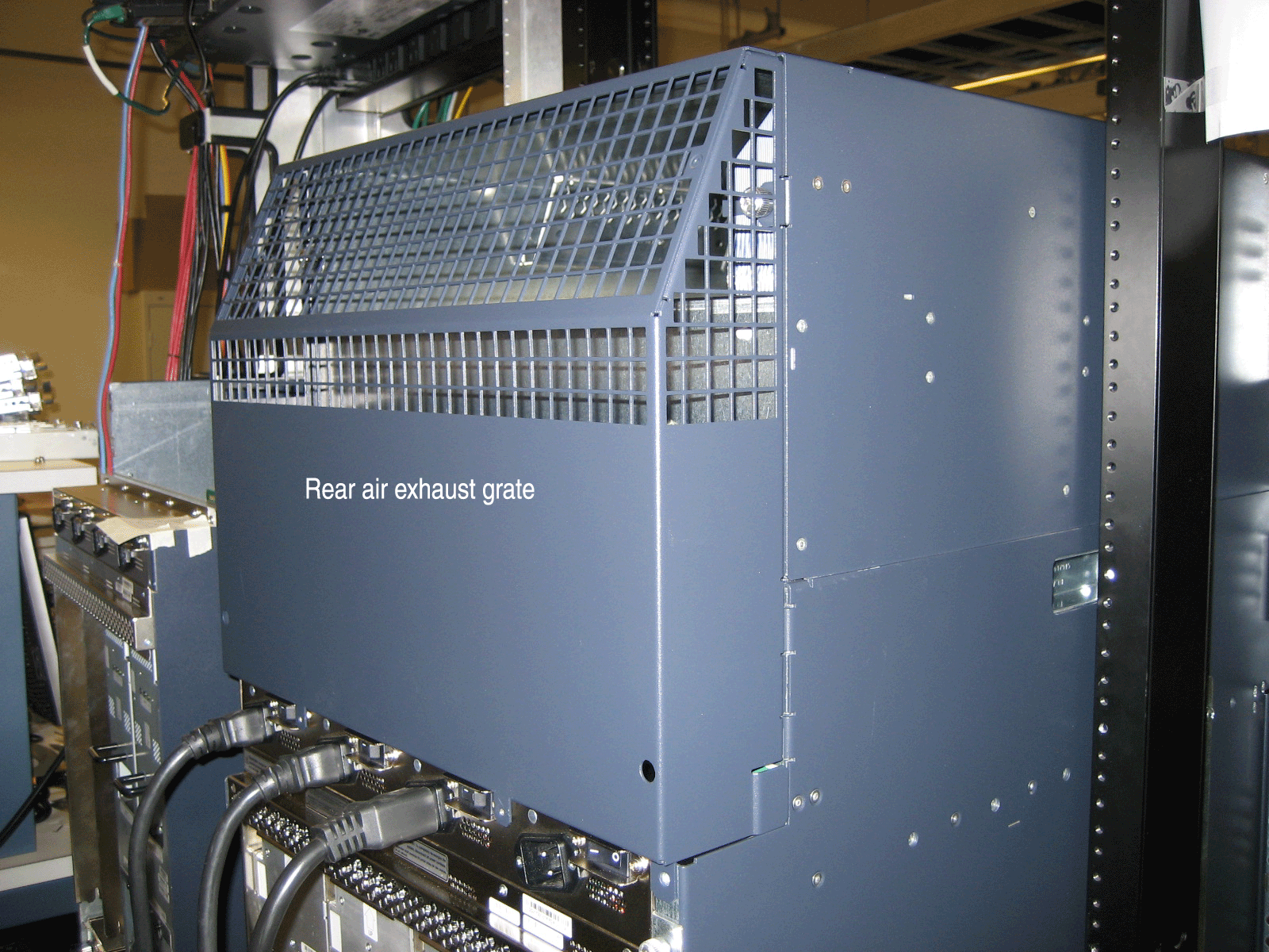
Rear air exhaust grate—Replaces the existing air exhaust grate and attaches to the rear of the top hat assembly and the chassis.
-
Cable routing bay cover—Covers the cable routing channels and attaches to the front of the top hat assembly.
-
Two 8-32 screws—Secure the top hat assembly to the rear of the chassis.
The extended cable manager contains two cable routing bays, and each bay contains six cable routing channels (see Figure 3, which shows the extended cable manager with its cover removed). Each routing channel corresponds to a DPC below it. You route the cables from a DPC through the bottom of a routing channel and out the side of the bay. The retaining flanges on each channel keep the cables inside the channels.
The extended cable manager is used in conjunction with the standard cable manager attached to the bottom of the chassis. We recommend that you use the standard cable manager for fiber-optic cables that cannot fit in the extended cable manager and for cables that do not connect to a DPC (such as an out-of-band Ethernet cable connected to the Routing Engine). See Dressing the Cables for more information about routing cables.
Installing the Extended Cable Manager
- Powering Off the Router
- Removing the Craft Interface
- Removing the Upper Fan Tray
- Removing the AC Power Inlet Cover (DC-Powered Routers Only)
- Removing the Rear Air Exhaust Grate
- Disconnecting the Craft Interface Ribbon Cable from the Chassis Midplane
- Removing the Original Top Hat of the Chassis
- Installing the Extended Cable Manager Top Hat
- Installing the New Rear Air Exhaust Grate
- Reinstalling the AC Power Inlet Cover (DC-Powered Routers Only)
- Reinstalling the Upper Fan Tray
- Reinstalling the Craft Interface
Powering Off the Router
You must power off the router before installing the extended cable manager. To power off the router, follow this procedure:
Removing the Craft Interface
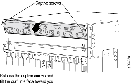
To remove the craft interface, follow this procedure (see Figure 4):
- Attach an electrostatic discharge (ESD) grounding strap to your bare wrist, and connect the strap to one of the ESD points on the chassis.
- Detach any external devices connected to the craft interface.
- Loosen the captive screws at the top left and right corners of the craft interface faceplate.
- Grasp the craft interface faceplate and carefully tilt it toward you until it is horizontal.
- Locate the latch on the inside of the craft interface. Grasp both sides of the latch on the inside of the craft interface and with your thumb and forefinger, gently press both sides of the latch to disengage it.
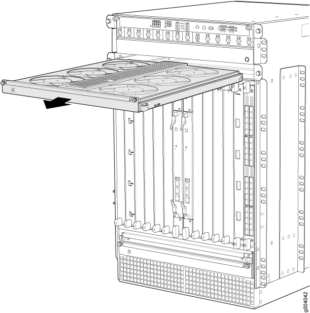
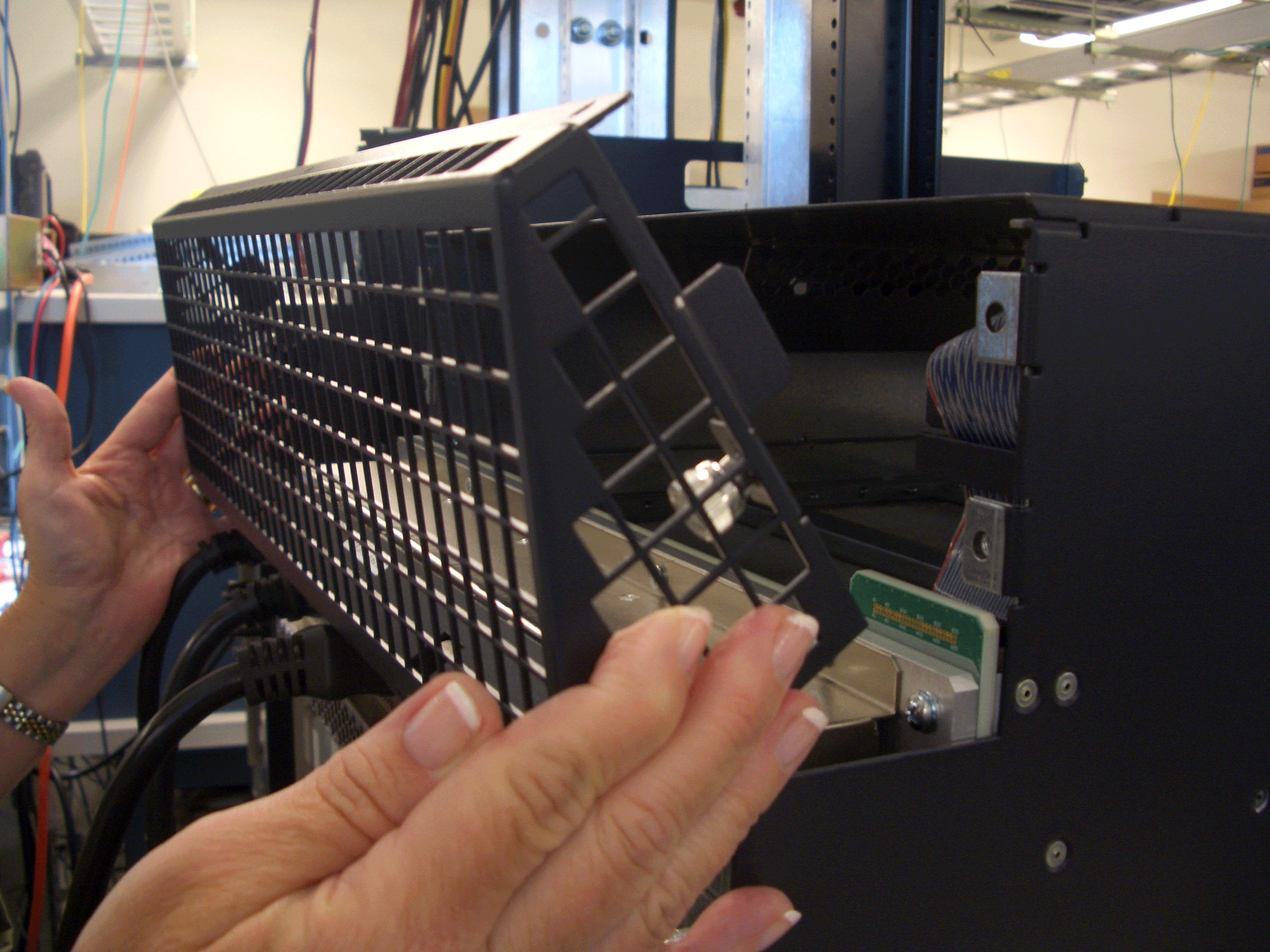
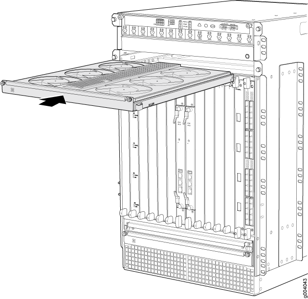
Removing the Upper Fan Tray
In the front of the chassis, the upper fan tray is located above the DPC card cage. The fan tray weighs about 13 lb (5.9 kg).
To remove the upper fan tray, follow this procedure (see Figure 5):
Figure 5 shows the craft interface installed in the chassis. You have already removed the craft interface.
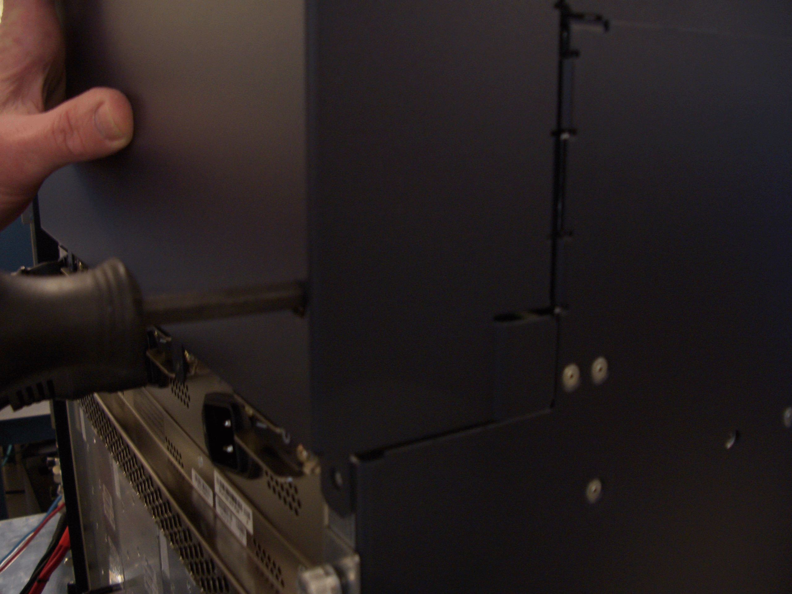
Removing the AC Power Inlet Cover (DC-Powered Routers Only)
A DC-powered router contains a cover over the four unused AC power inlets in the rear of the chassis. If you have a DC-powered router, remove the cover by following this procedure:
-
With a Phillips screwdriver, loosen the three screws that
secure the cover to the back of the chassis (see Figure 6). Take care to prevent
the cover from falling off the chassis after you remove the last screw.
Save the three screws, which will be needed later to secure the cover to the chassis.
Figure 6: Removing the AC Power Inlet Cover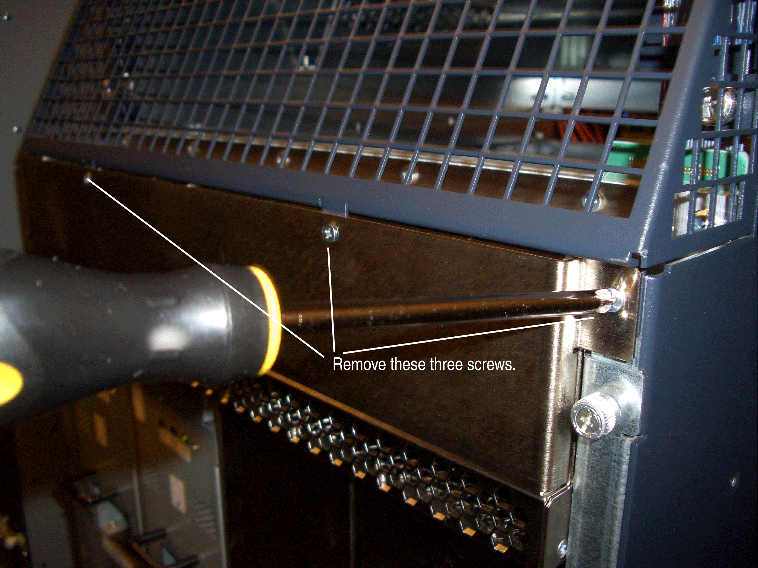
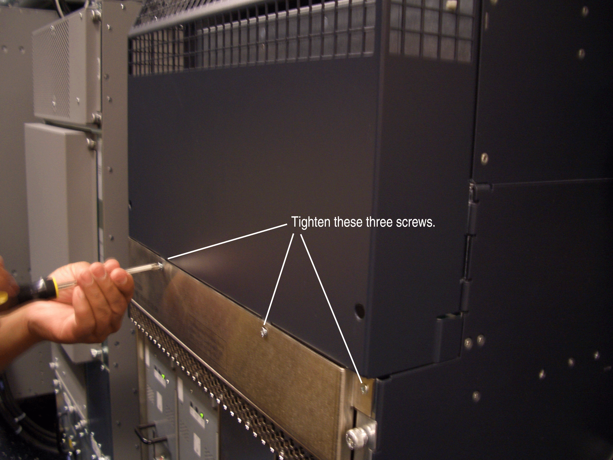
Removing the Rear Air Exhaust Grate
To remove the rear air exhaust grate, follow this procedure:
-
With a flat-blade or Phillips screwdriver, loosen the two captive screws that
secure the grate to the back of the chassis (see Figure 7 and Figure 8).
Figure 7: Removing the Right Captive Screw of the Rear Air Exhaust Grate
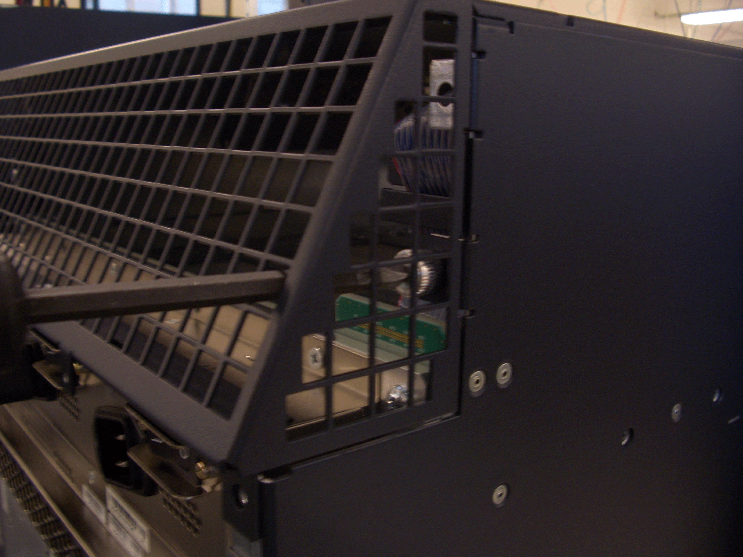 Figure 8: Removing the Left Captive Screw of the Rear Air Exhaust Grate
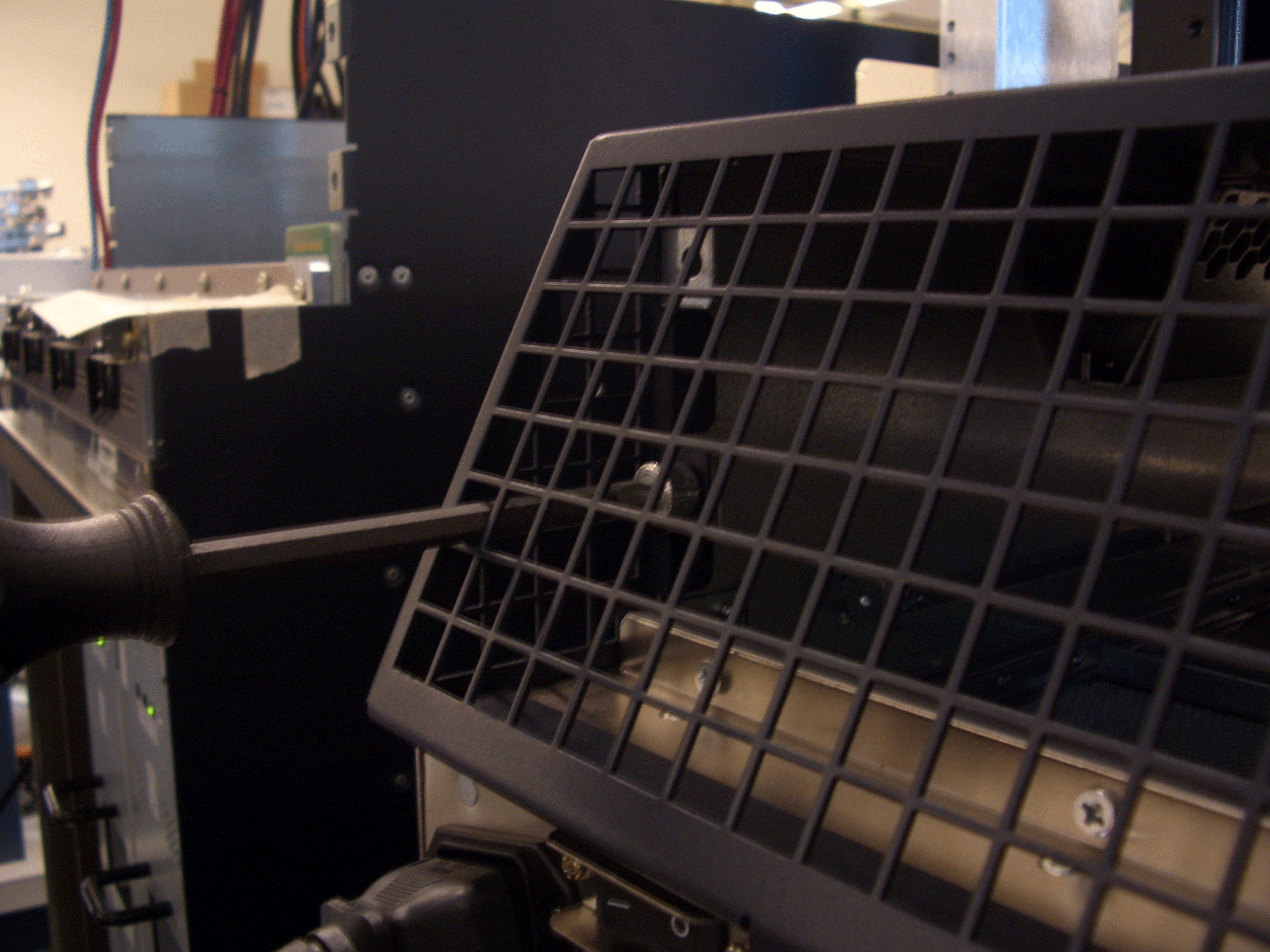
-
With a flat-blade or Phillips screwdriver, remove the three screws that secure the
grate to the top of the chassis (see Figure 9 through Figure 11). These three screws are no longer needed.
CAUTION:
To avoid damaging the router, take care to avoid dropping any screws into the router.
Figure 9: Removing the Top Right Screw of the Rear Air Exhaust Grate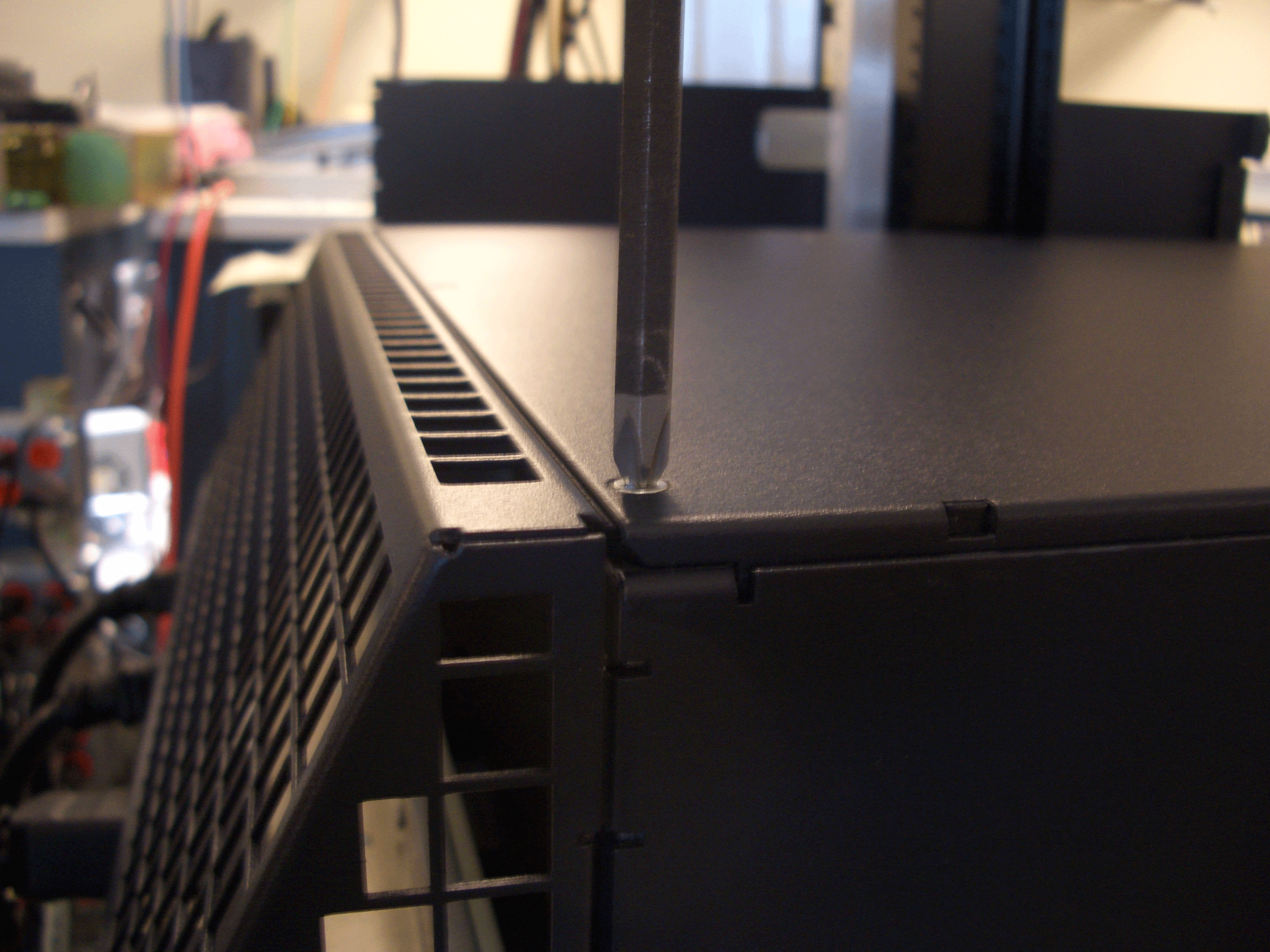 Figure 10: Removing the Top Middle Screw of the Rear Air Exhaust Grate
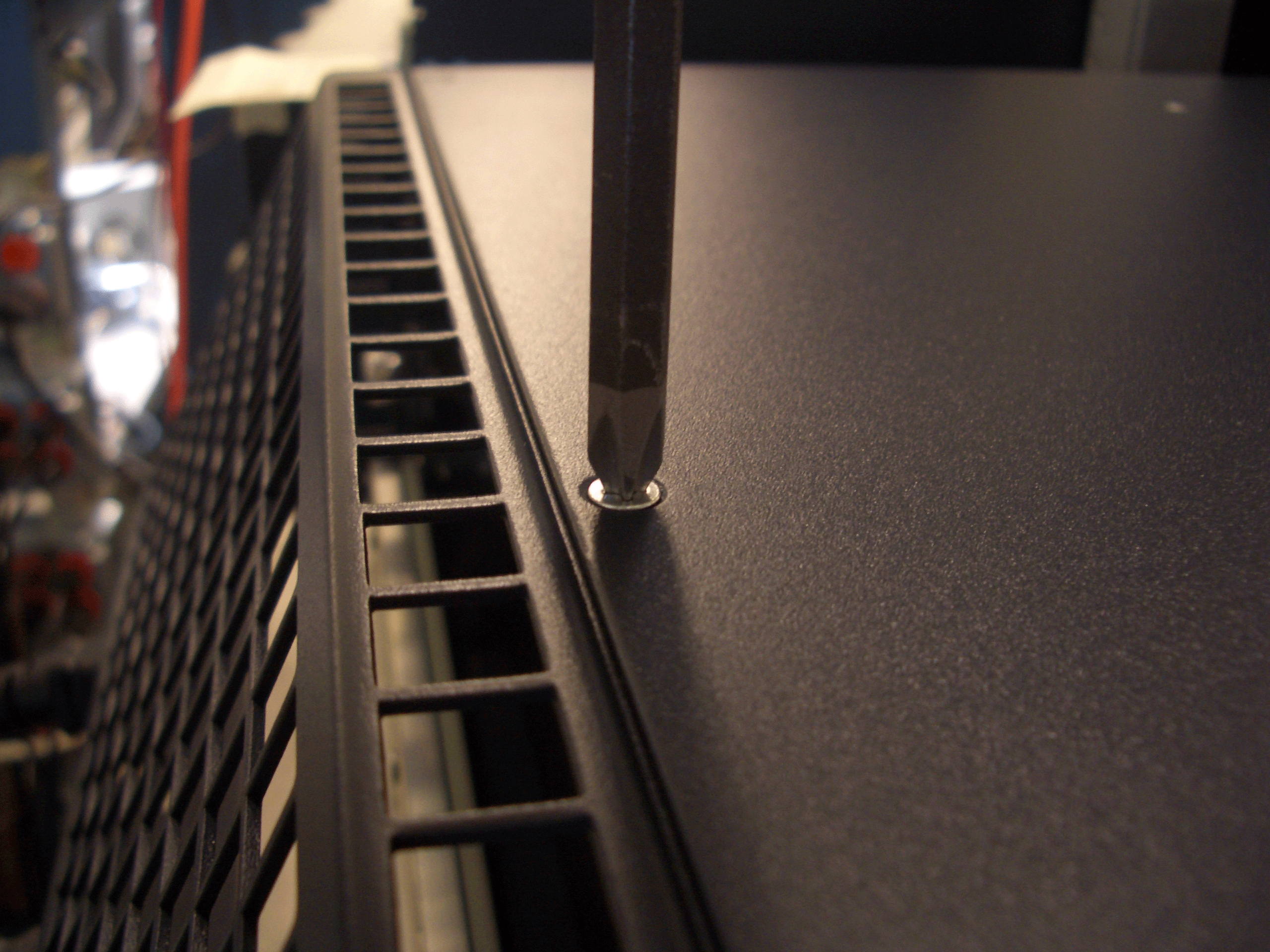 Figure 11: Removing the Top Left Screw of the Rear Air Exhaust Grate
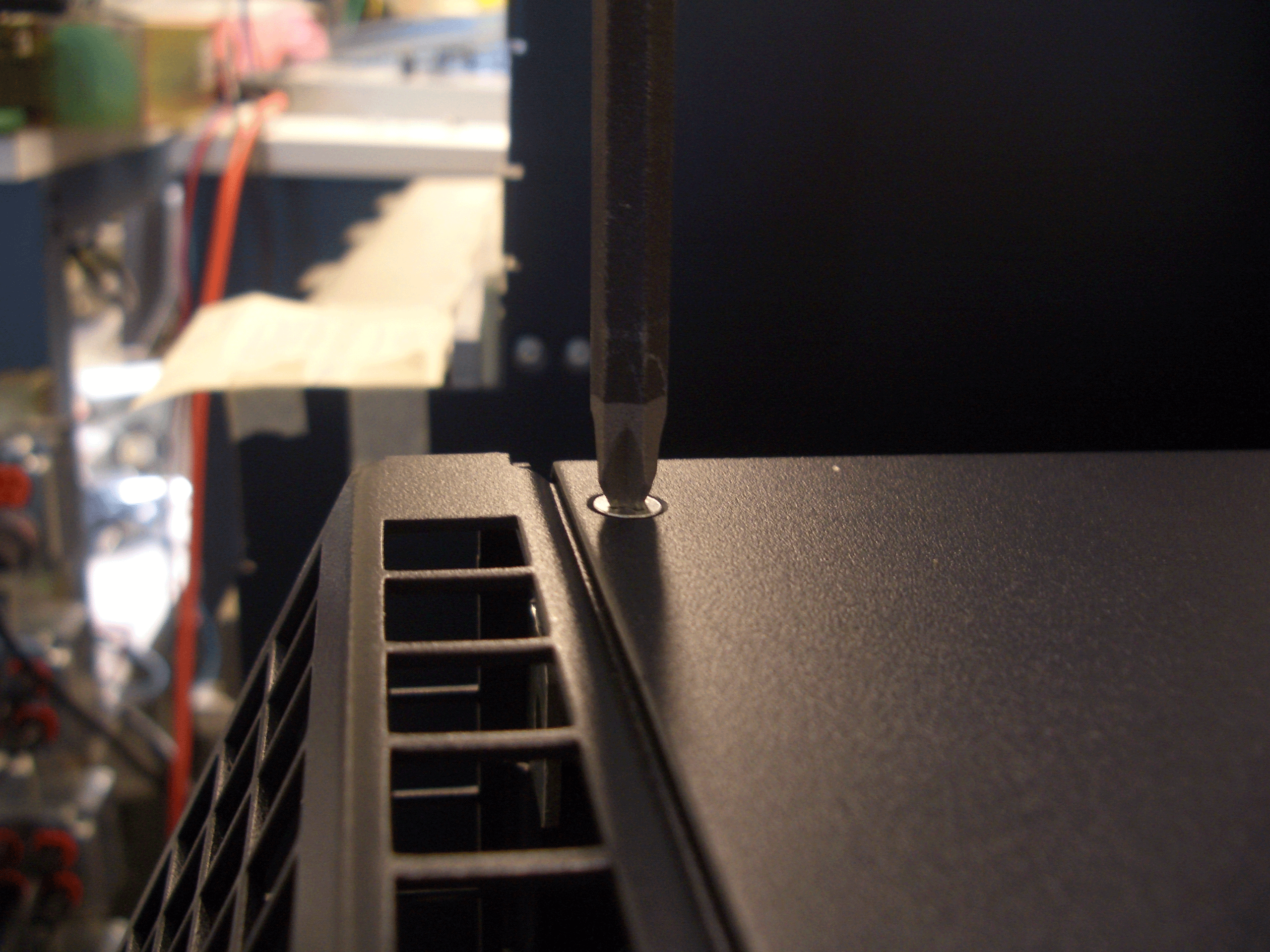
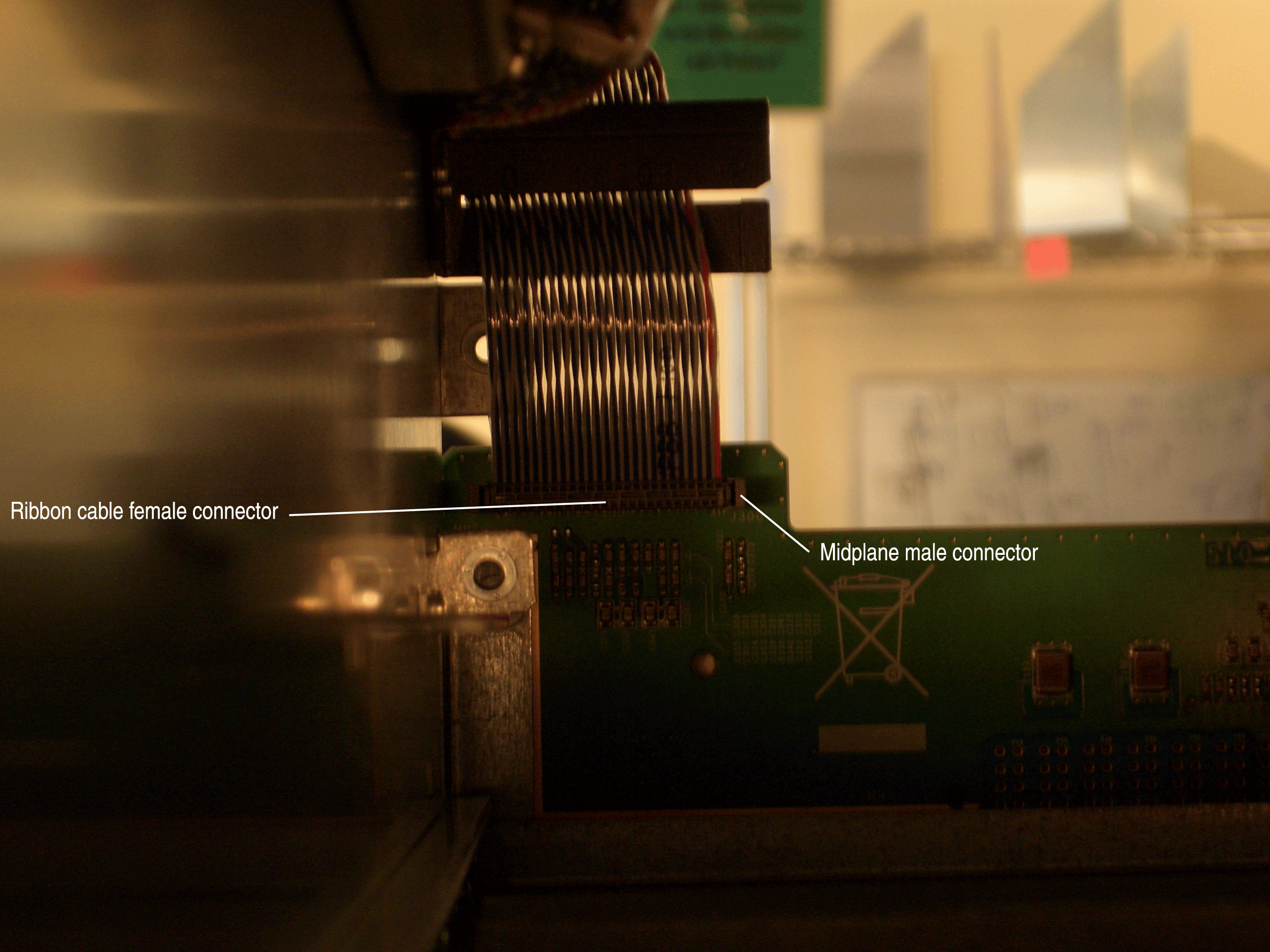
Disconnecting the Craft Interface Ribbon Cable from the Chassis Midplane
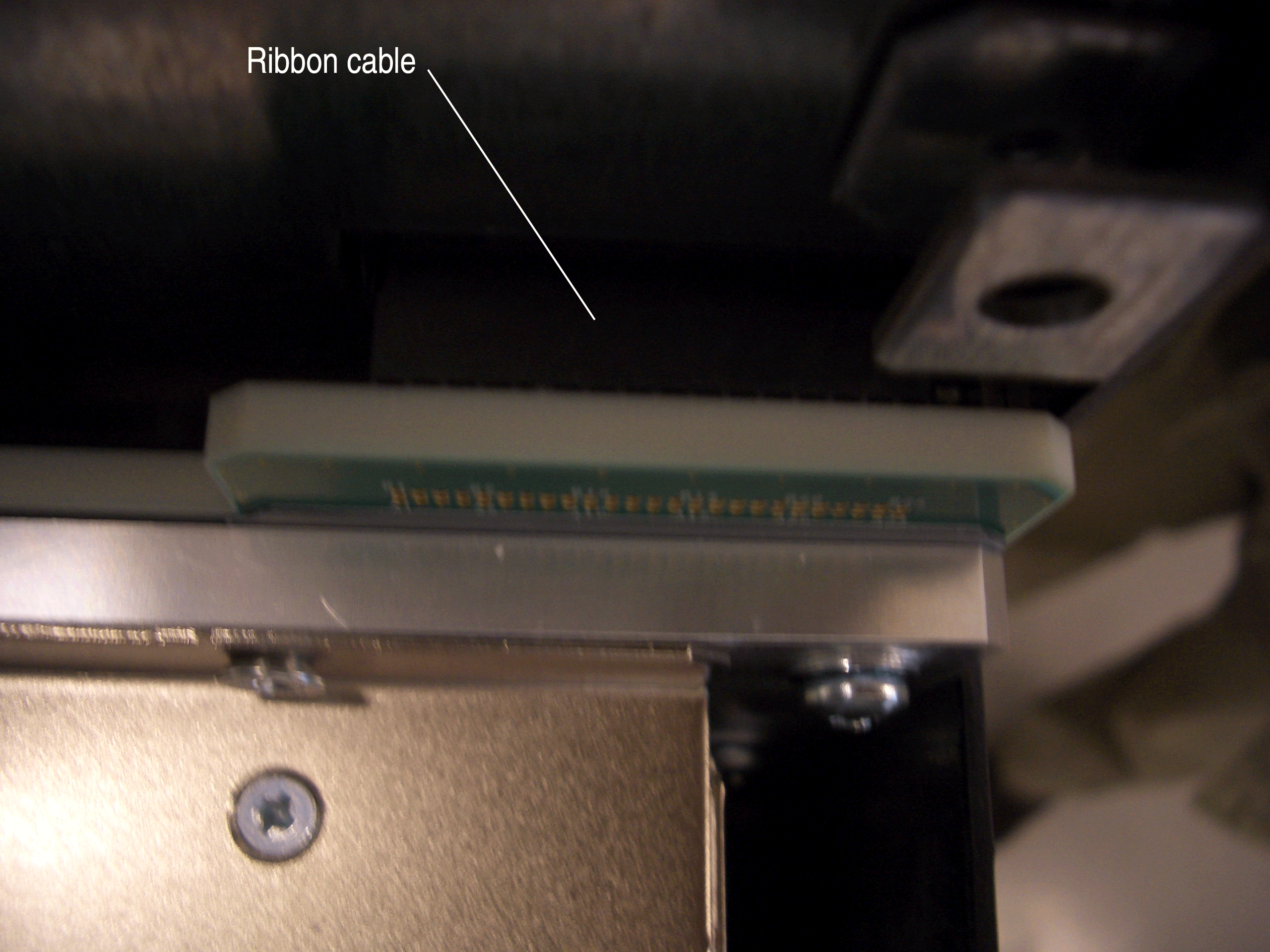
The craft interface communicates with the router through a ribbon cable that is attached to the original top hat. Attached to the end of the ribbon cable is a socket connector that plugs into a plug connector on the chassis midplane. The socket connector contains a small mating clip on each of its sides. During normal operation, the socket connector is plugged inside the plug connector and is held into place by the mating clips. Figure 13 shows the ribbon cable plugged into the plug connector (viewed from the front of the chassis).
The craft interface ribbon cable must be disconnected from the midplane connector before the top hat of the chassis can be removed (as described in Removing the Original Top Hat of the Chassis).
To disconnect the ribbon cable from the chassis midplane, follow this procedure (see Figure 13):
Removing the Original Top Hat of the Chassis
To remove the original top hat from the chassis, follow this procedure:
-
With a 3/8-in. hexagonal-head external drive socket wrench
or nut driver, remove the four acorn nuts that secure the top hat
to the chassis (see Figure 14 and Figure 15). Save these
four nuts, which will be needed later to secure the extended cable manager top
hat.
Figure 14: Removing the Two Right Acorn Nuts That Secure the Original Top Hat
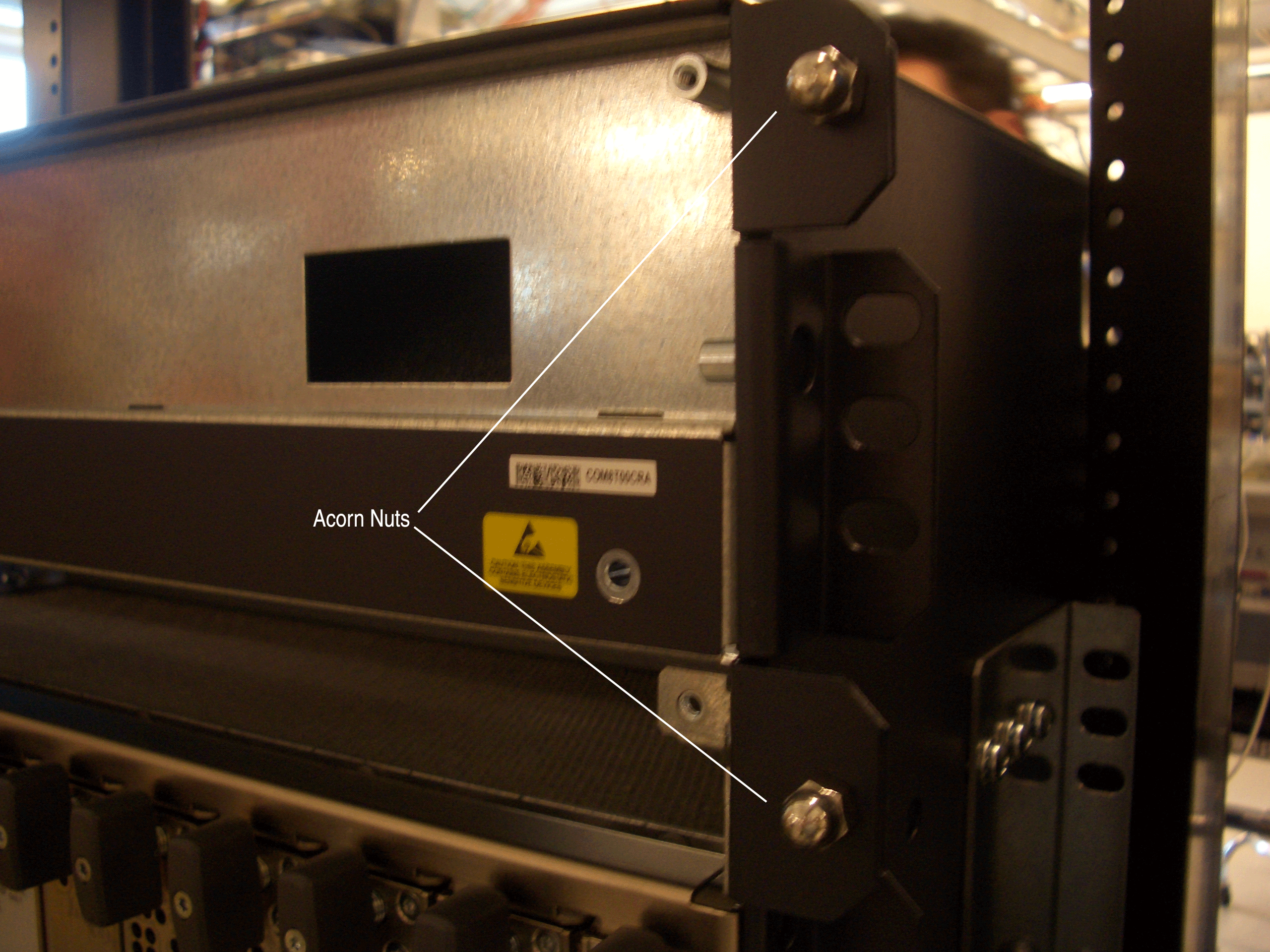 Figure 15: Removing the Two Left Acorn Nuts That Secure the Original Top Hat
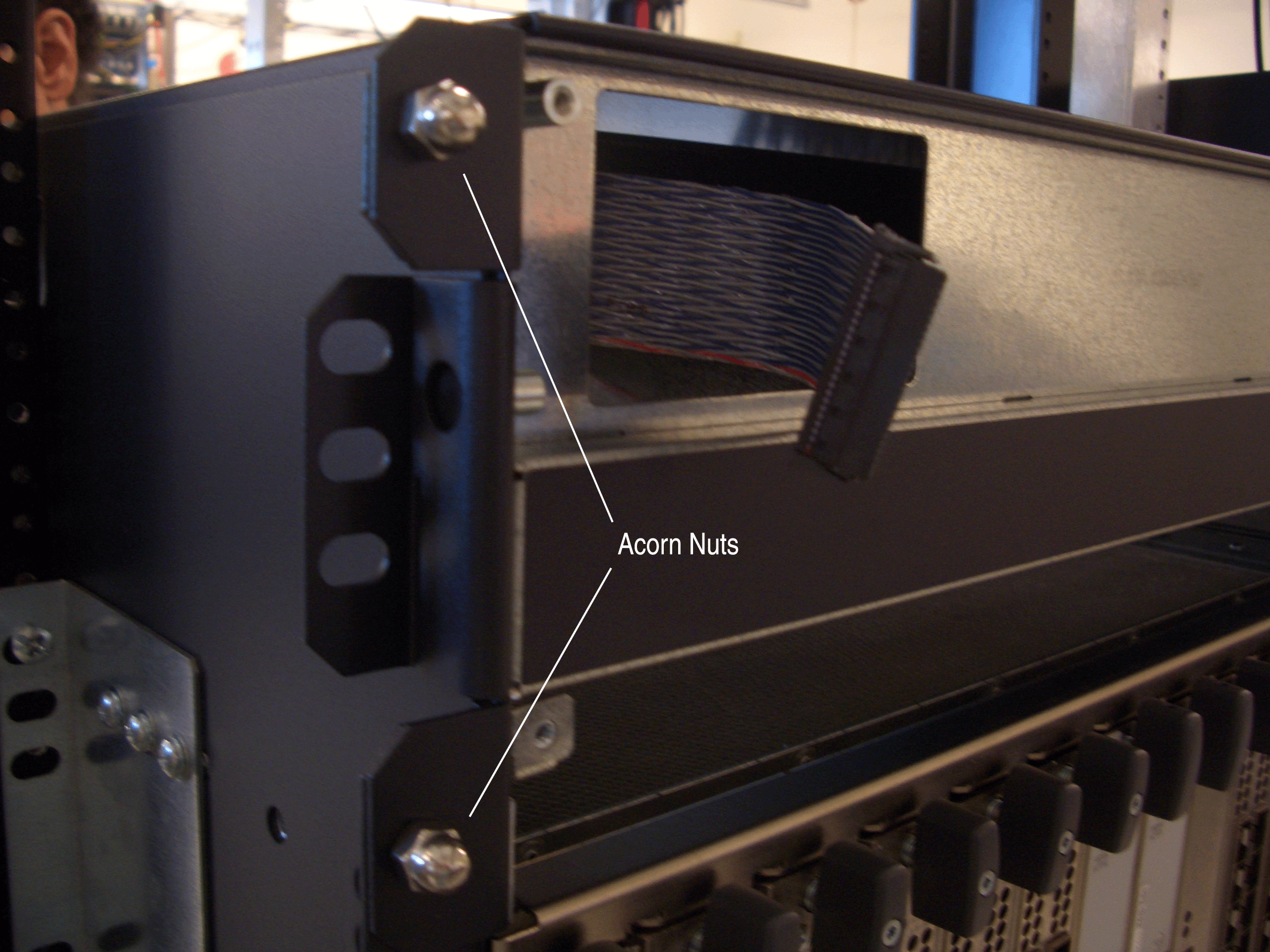
Installing the Extended Cable Manager Top Hat
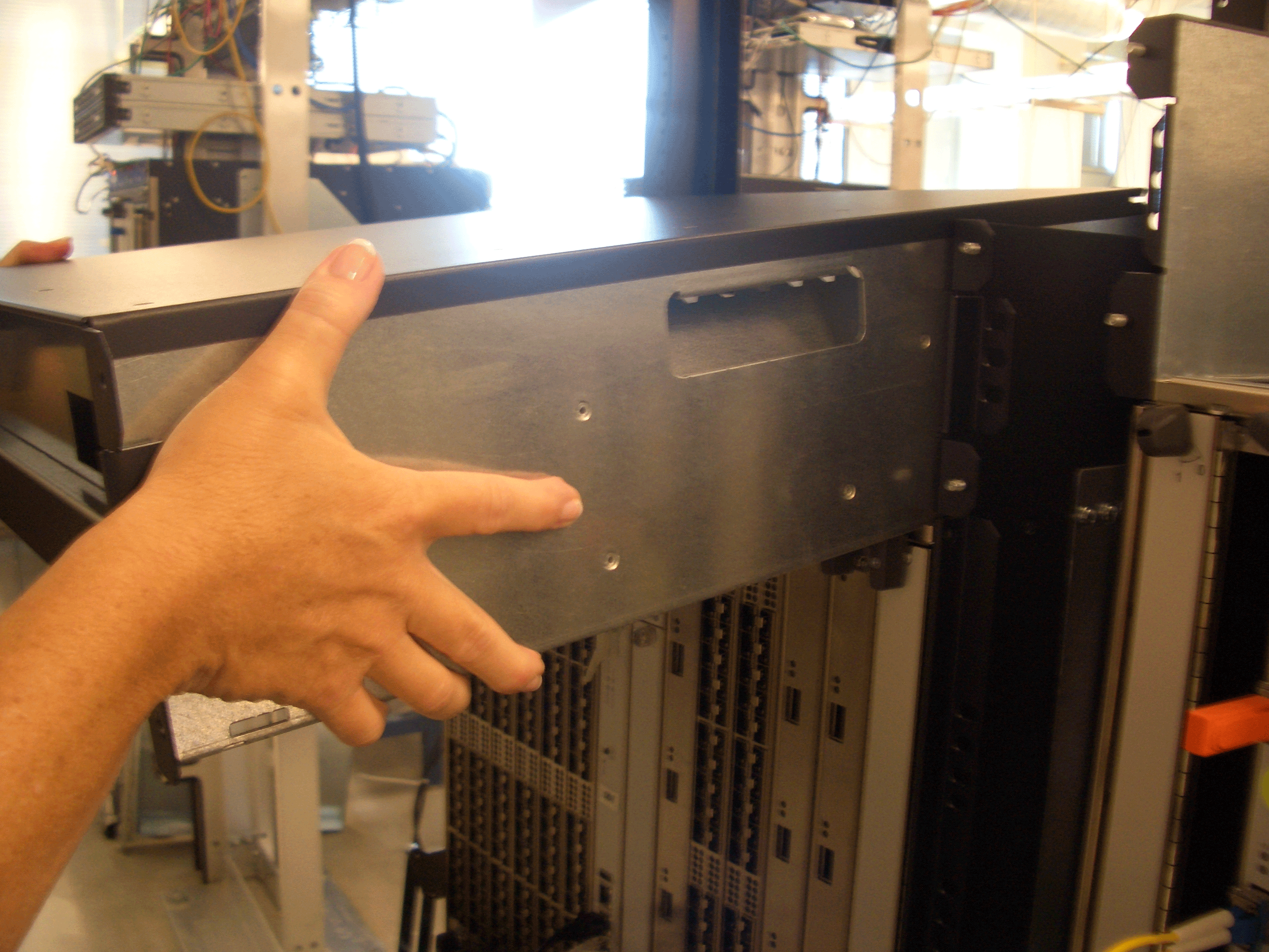
To install the extended cable manager top hat in the chassis, follow this procedure (the top hat weighs (40 lbs [18 kg]):
-
Lift the top hat into place over the top of the chassis
and rest it on the flanges along the side panels of the chassis (see Figure 18).
Figure 18: Resting the Top Hat on the Chassis
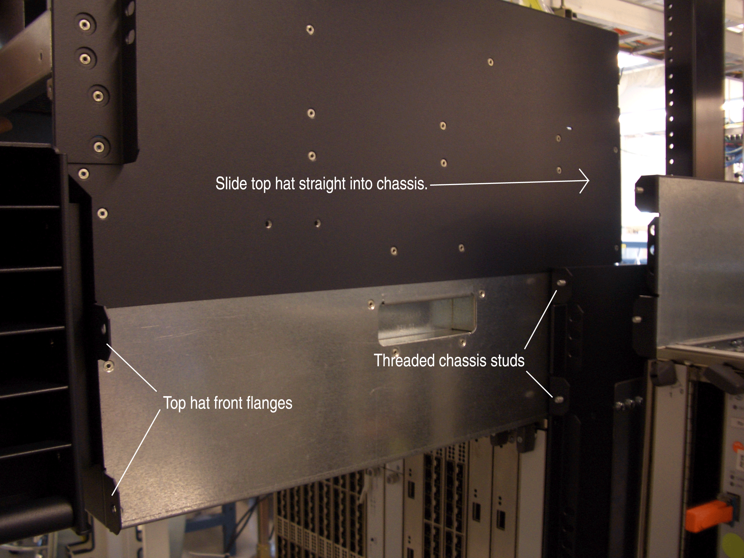
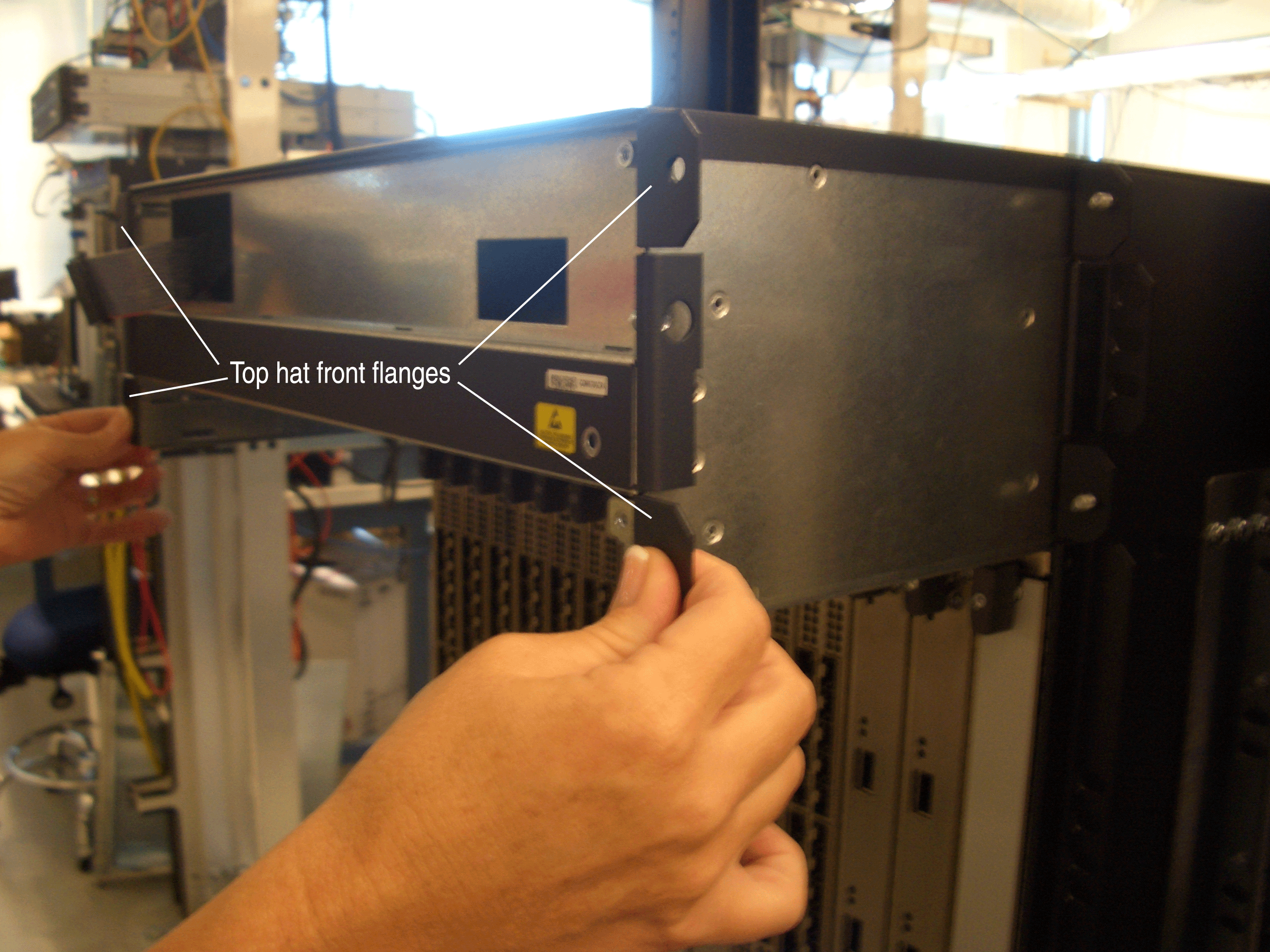
-
Slowly slide the top hat straight into the chassis until
the front flanges are approximately 3/8-in. away from the corresponding
chassis flanges. The threaded studs in the chassis flanges should
be aligned with the center of the holes in the top hat front flanges
(see Figure 19).
The 3/8-in. clearance is required to see the chassis midplane connector to which the craft interface ribbon cable connects. (The craft interface ribbon cable is attached to the extended cable manager top hat.)
Figure 19: Extended Cable Manager Top Hat Installed with 3/8-in. Clearance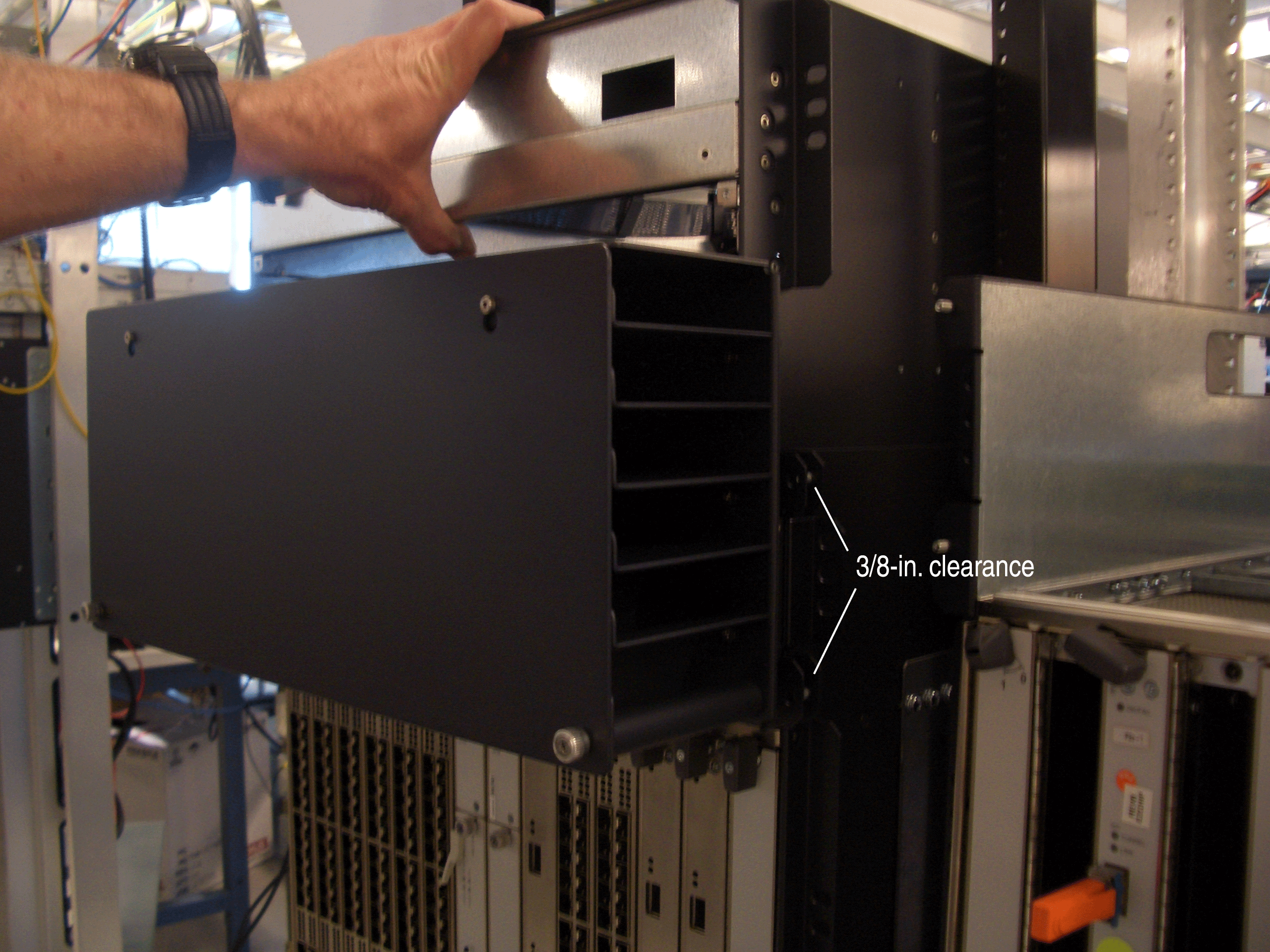
-
Connect the craft interface ribbon cable:
Figure 20: Extended Cable Manager Craft Interface Ribbon Cable Connected to the Chassis Midplane
-
To close the 3/8-in. clearance, slide the top hat straight
into the chassis until the front flanges are flush with the corresponding
chassis flanges.
When the top hat comes to a stop, a double-sided electrical connector on the rear of the top hat is mated with the midplane connector in which the upper fan tray used to mate (see Figure 21, which is a view looking down into the chassis from the rear). The other side of the top hat connector is where the fan tray connector will mate when it is reinstalled in the chassis.
Figure 21: Fan Tray Connector on Extended Cable Manager Top Hat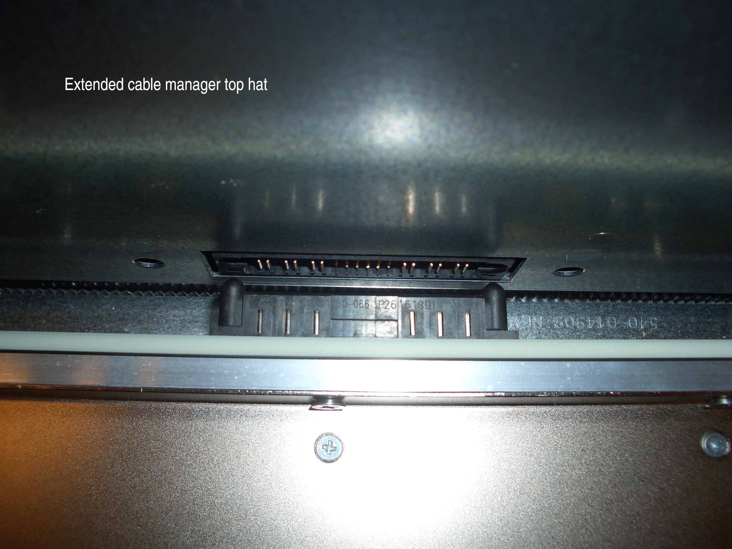
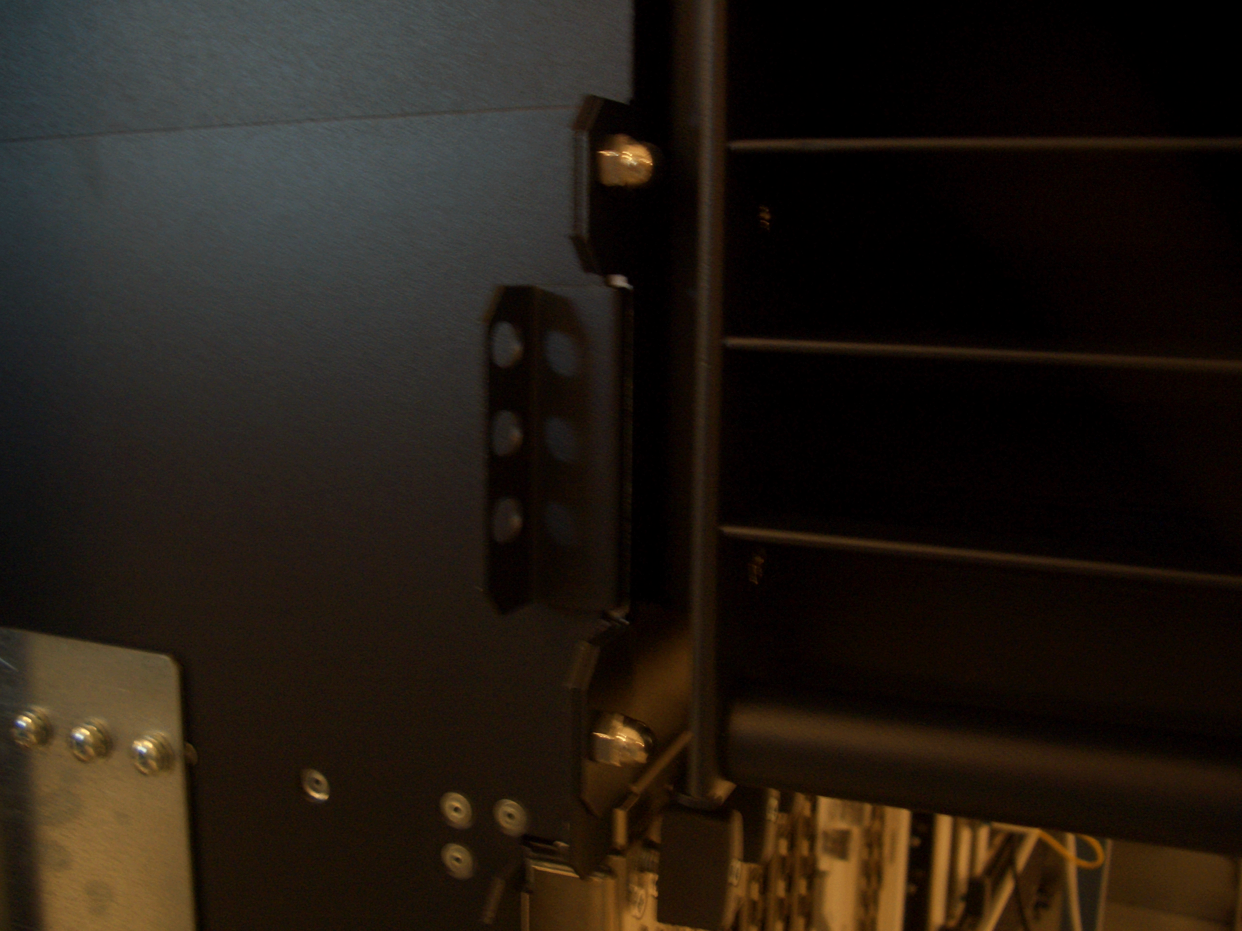
-
Using the four acorn nuts saved in Removing the Original Top Hat of the Chassis, secure the top hat
to the front of the chassis by tightening the nuts on the threaded
studs inside the holes in the top hat front flanges (see Figure 22). Use a 3/8-in. wrench to
access the nuts between the top hat front flanges and the rear of
the routing channel bays.
Figure 22: Tightening the Four Acorn Nuts That Secure the Extended Cable Manager Top Hat
-
Secure the top hat to the rear of the chassis by inserting
and tightening two 8-32 screws into the upper threaded chassis holes,
as shown in Figure 23 and Figure 24.
Note:
The threaded holes immediately below those used to secure the top hat are used to secure the new extended cable manager rear exhaust grate. Make sure that you use the correct holes for securing the top hat.
Figure 23: Tightening the Right 8-32 Screw for the Extended Cable Manager Top Hat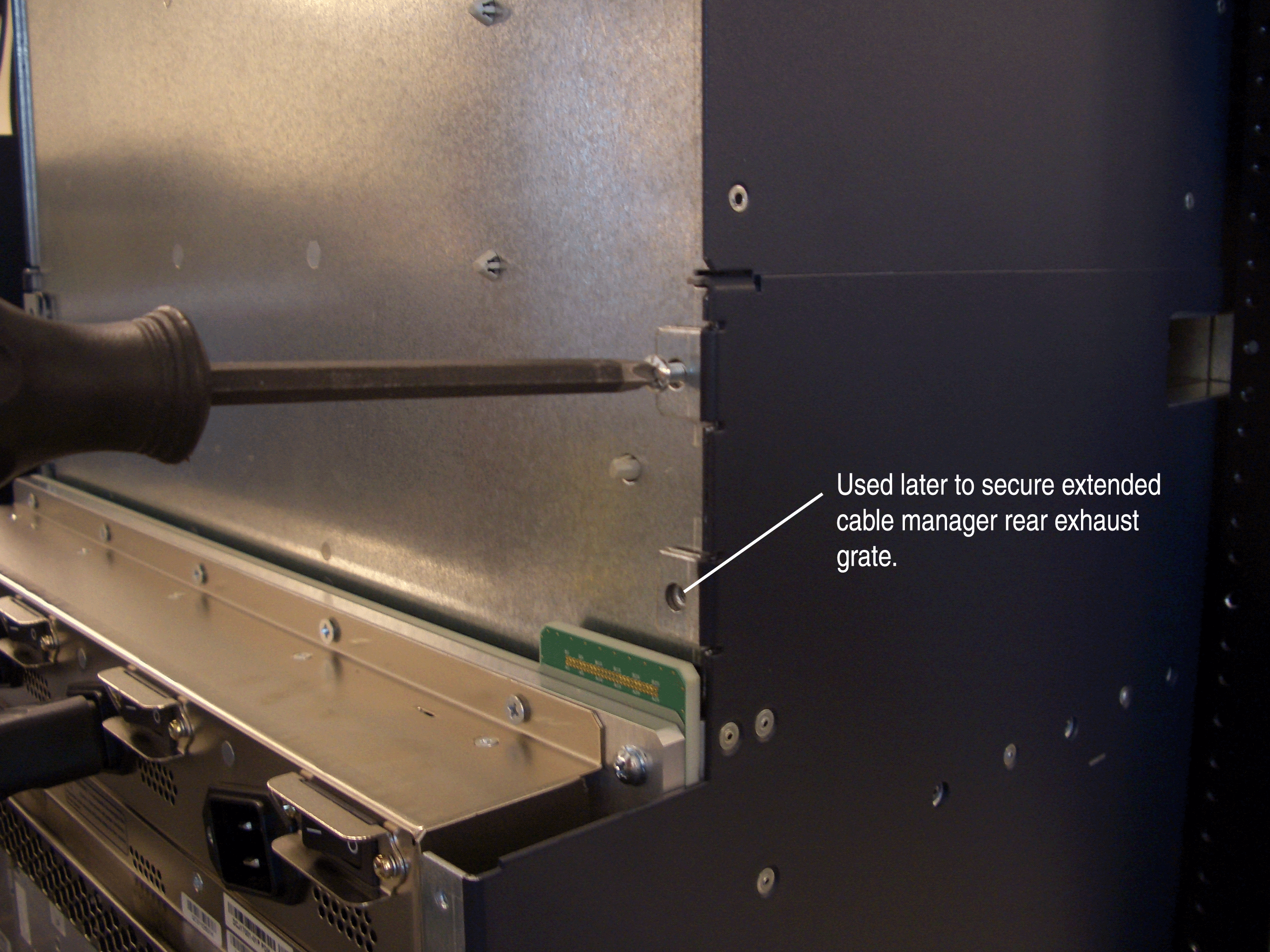 Figure 24: Tightening the Left 8-32 Screw for the Extended Cable Manager Top Hat
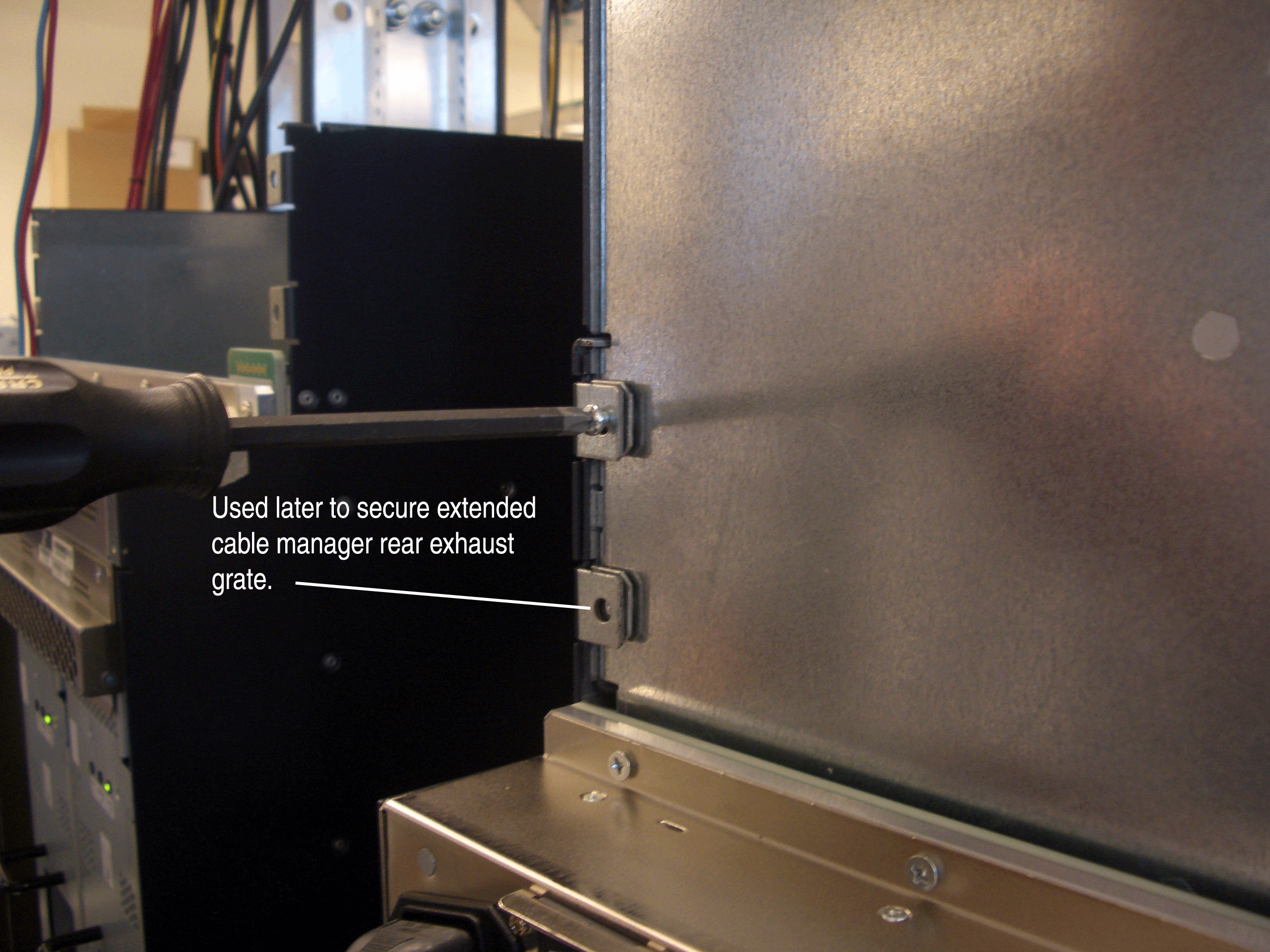
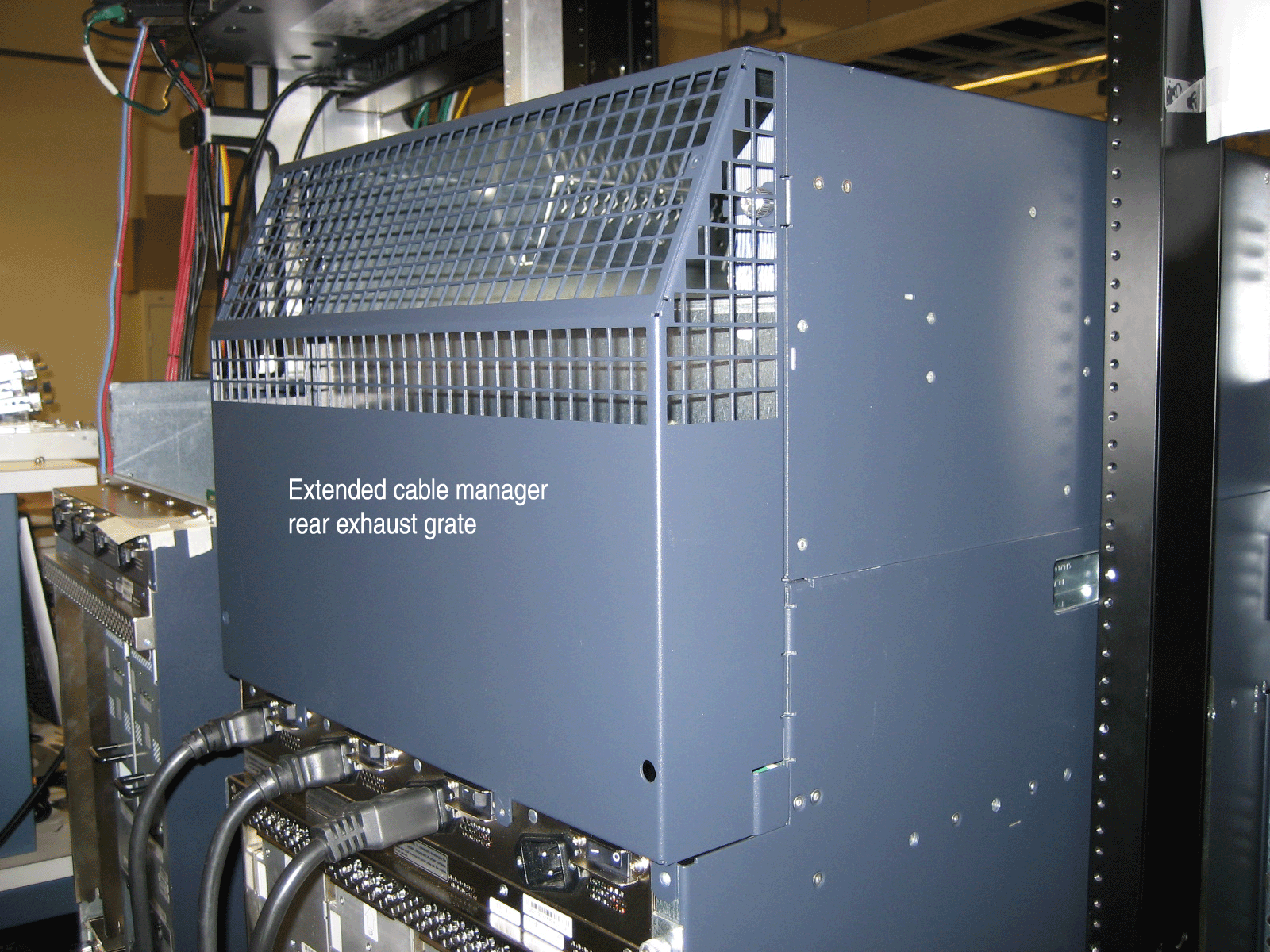
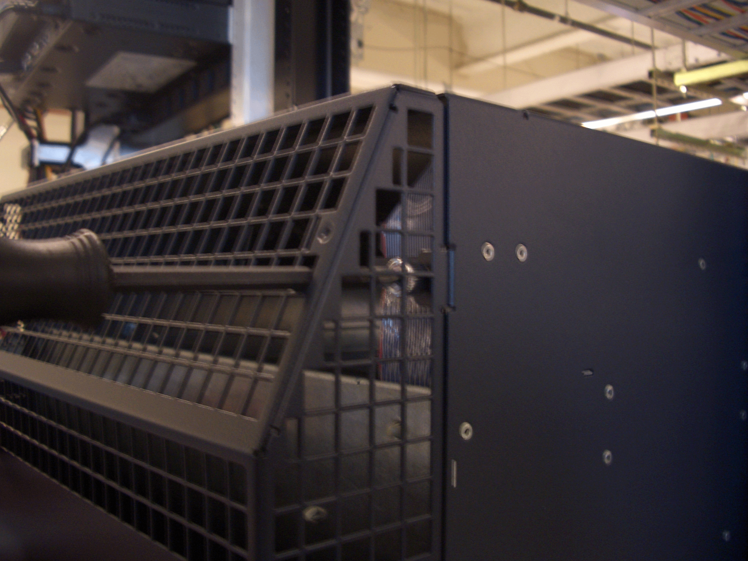
Installing the New Rear Air Exhaust Grate
To install the new rear air exhaust grate, follow this procedure:
-
Lift the grate into place at the top rear of the chassis.
The sides and the top of the grate should be flush with the sides
and top of the chassis (see Figure 25).
Figure 25: Installing the New Rear Air Exhaust Grate
- With a flat-blade or Phillips screwdriver, partly tighten the top two captive screws, then the bottom two captive screws, that secure the grate to the chassis.
Reinstalling the AC Power Inlet Cover (DC-Powered Routers Only)
To reinstall the cover over the four unused AC power inlets in a DC-powered router, follow this procedure:
-
Using the three screws saved in Removing the AC Power Inlet Cover (DC-Powered Routers Only), secure the cover
to the chassis by partly tightening each of the screws (see Figure 28).
Figure 28: Removing the AC Power Inlet Cover
Reinstalling the Upper Fan Tray
To reinstall the upper fan tray, follow this procedure (see Figure 29):
Figure 29 does not show the extended cable manager and shows the craft interface installed in the chassis. You have not yet installed the craft interface.
- Attach an electrostatic discharge (ESD) grounding strap to your bare wrist, and connect the strap to one of the ESD points on the chassis.
- Grasp the fan tray on each side and insert it straight into the chassis. Note the correct orientation by the "this side up" label on the top surface of the fan tray.
- Tighten the captive screws on each side of the fan tray faceplate to secure it in the chassis.
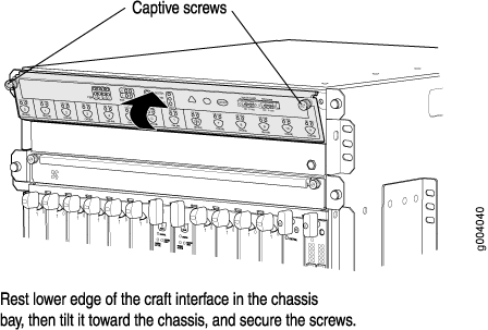
Reinstalling the Craft Interface
To reinstall the craft interface, follow this procedure (see Figure 30):
Figure 30 does not show the extended cable manager installed.
- Attach an electrostatic discharge (ESD) grounding strap to your bare wrist, and connect the strap to one of the ESD points on the chassis.
- Grasp the craft interface with one hand and hold the bottom edge of the craft interface with the other hand to support its weight.
- Align the red line along the bottom of the internal strap with the bottom of the connector and snap gently into place.
- Align the bottom of the craft interface with the sheet metal above the DPC card cage and press it into place.
- Tighten the screws at the top left and right corners of the craft interface faceplate.
- Reattach any external devices connected to the craft interface.
Powering On the Router
To power on the router, follow this procedure:
Verifying the Extended Cable Manager Is Correctly Installed
To verify that the extended cable manager is correctly installed, follow this procedure:
Dressing the Cables
To dress the cables within the extended cable manager, follow this procedure: