Help us improve your experience.

Let us know what you think.

Do you have time for a two-minute survey?


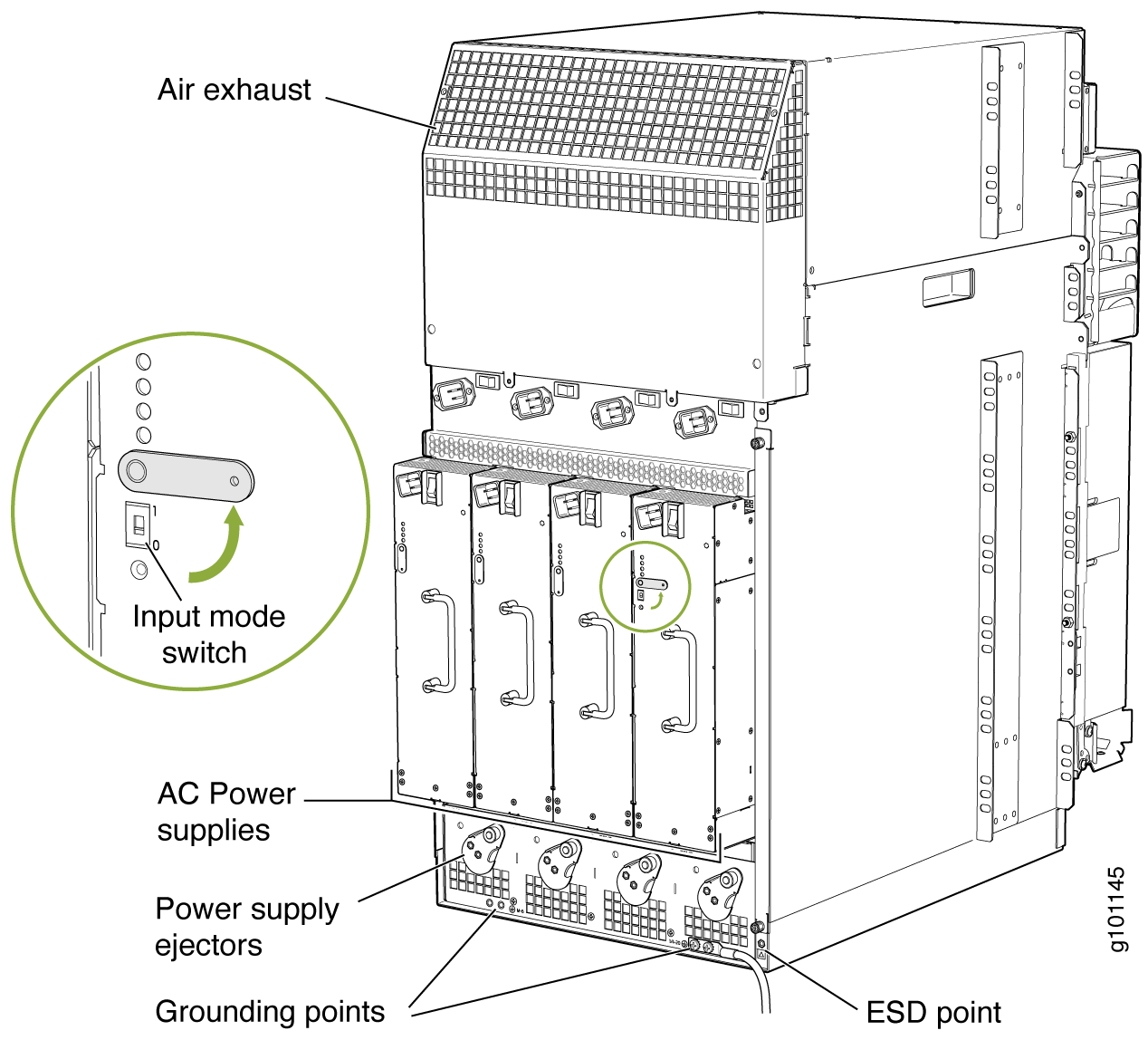
Connecting Power to an AC-Powered MX960 Router with High-Capacity Power Supplies

Note:

A minimum of two AC nominal 220 VAC 20 amp power cords are required for this procedure.

To connect the AC power cords to the router (see Figure 1).

  1. Verify that the power switch on the power supply is in the off  (O) position.
  2. Ensure that the release lever below the empty power supply slot is locked in the counterclockwise position (see Figure 1).
    Figure 1: MX960 with High-Capacity AC Power Supplies InstalledMX960 with High-Capacity AC Power Supplies Installed
    Note:

    The chassis is shown with the extended cable manager.

    If necessary, pull the spring-loaded locking pin in the release lever away from the chassis and turn the release lever counterclockwise until it stops. Let go of the locking pin in the release lever. Ensure that the pin is seated inside the corresponding hole in the chassis.

  3. On the power supply, rotate the metal cover away from the input mode switch to expose the switch.
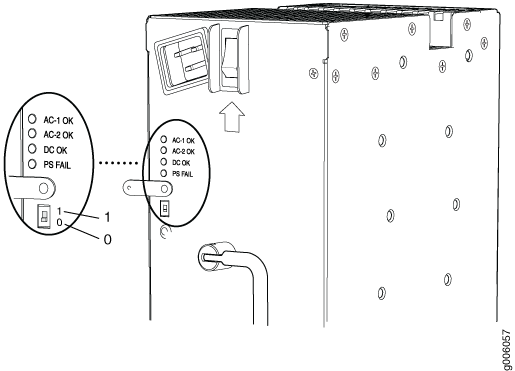
  4. Move the input mode switch to position 0 if you plan to connect one feed, or position 1 if you plan to connect two feeds (see Figure 2).
    Figure 2: MX960 AC Power Input Mode SwitchMX960 AC Power Input Mode Switch
    CAUTION:

    Do not use a pencil, because fragments can break off and cause damage to the power supply.

  5. Using both hands, slide the power supply straight into the chassis until the power supply is fully seated in the chassis slot. The power supply faceplate will protrude beyond the chassis.

    The small tab on the metal housing that is controlled by the release lever must be inside of the corresponding slot at the bottom of the power supply (see Figure 2). This tab is used to pull the power supply down in the chassis slot, prior to removing the power supply.

  6. While firmly pushing the handle on the power supply faceplate with one hand, use your other hand to pull the spring-loaded locking pin in the release lever away from the chassis and turn the release lever clockwise until it stops.
  7. Let go of the locking pin in the release lever. Ensure that the pin is seated inside the corresponding hole in the chassis.
  8. Make sure the grounding cable is attached, see Grounding the MX960 Router.
  9. Locate a power cord with the type of plug appropriate for your geographical location (see AC Power Cord Specifications for the MX960 Router).
  10. Plug the power cord into the corresponding appliance inlet located in the chassis directly above the power supply. This is the recommend receptacle when using the power supply in one-feed mode. If using the power supply in two-feed mode, plug the second power cord into the receptacle on the power supply.
    Note:

    Each power supply must be connected to a dedicated AC power feed and a dedicated customer site circuit breaker.

    Note:

    To use HC-PSs with full capacity you have to switch them to two feed mode and use two power cords per HC-PS.

  11. Dress the power cords appropriately. Verify that the power cord does not block the air exhaust and access to router components, and that they do not drape where people could trip on them.
  12. Move the AC input switch above the power supply to the on () position. This is the only switch you have to turn on if you are using the power supply in one feed mode. If using the power supply in two-feed mode, move the power switch on the power supply to the on position. Remember to turn on both switches when operating the power supply in two-feed mode.
  13. If the power supply is correctly installed and functioning normally, the AC1 OK, AC2 OK (two-feed mode only) DC OK LEDs light steadily, and the PS FAIL LED is not lit. See Table 1.
    Table 1: MX960 High-Capacity AC Power Supply LEDs

    Connected Inputs

    DIP Switch Position

    LEDs

    AC-1 OK

    AC-2 OK

    DC OK

    PS FAIL

    PDM connected, power supply disconnected

    0 (1 input)

    Green

    Off

    Green

    Off

    PDM disconnected, power supply connected

    0 (1 input)

    Off

    Green

    Green

    Off

    PDM connected, power supply connected

    0 (1 input)

    Green

    Green

    Green

    Off

    PDM connected, power supply disconnected

    1 (2 inputs)

    Green

    Off

    Off

    Red

    PDM disconnected, power supply connected

    1 (2 inputs)

    Off

    Green

    Off

    Red

    PDM connected, power supply connected

    1 (2 inputs)

    Green

    Green

    Green

    Off

    Note: The corresponding appliance inlet located in the chassis directly above the power supply is the recommend receptacle when using the power supply in one feed mode. If using the power supply in two-feed mode, plug the second power cord into the receptacle on the power supply
    Note: PDM in the above table stands for Power Distribution Module.
    
  14. Repeat steps 1-12 for installing power supplies in slots 1, 2, and 3, where required.