Converting from DC to AC Power Supplies on an MX960 Router
The conversion of an MX960 router from AC to DC or DC to AC should be performed with the system completely powered off. A system cannot operate with a mix of AC and DC power supplies. This procedure assumes conversion from normal-capacity power supplies to high-capacity power supplies.
Remove MX960 normal-capacity DC power supplies for power supply in slots 0, 1, 2, 3 where present. All power supplies should be removed proceeding with the installation of the AC power supplies. To convert from DC to AC, use the following procedures.
To remove a normal-capacity DC power supply (see Figure 1):
-
Repeat steps 1-12 for power supplies in slot 1, 2, and
3, where present.
Figure 1: Removing a DC Power Supply from the MX960 Router
 Note:
Note:The chassis is shown without the extended cable manager.
Use the following procedures to install the MX960 high-capacity AC power supplies, the high-capacity second-generation AC power supplies, or the high-voltage second-generation universal power supplies in slots 0, 1, 2, and 3, where present.
During the upgrade process, you can simultaneously run normal-capacity and high-capacity power supplies. However, it is recommended to upgrade all power supplies to high-capacity power supplies.
To install an MX960 high-capacity AC or high-capacity second-generation power supply, use the following procedure (see Figure 2).
-
Verify that the power switch on the power supply is in the off (O) position.
-
Ensure that the release lever below the empty power supply slot is locked in the counterclockwise position (see Figure 2).
Figure 2: MX960 with High-Capacity AC Power Supplies Installed Note:
Note:The chassis is shown without the extended cable manager.
Figure 3: Rear View of a Fully Configured AC-powered High-Capacity Second-Generation Powered MX960 Router Chassis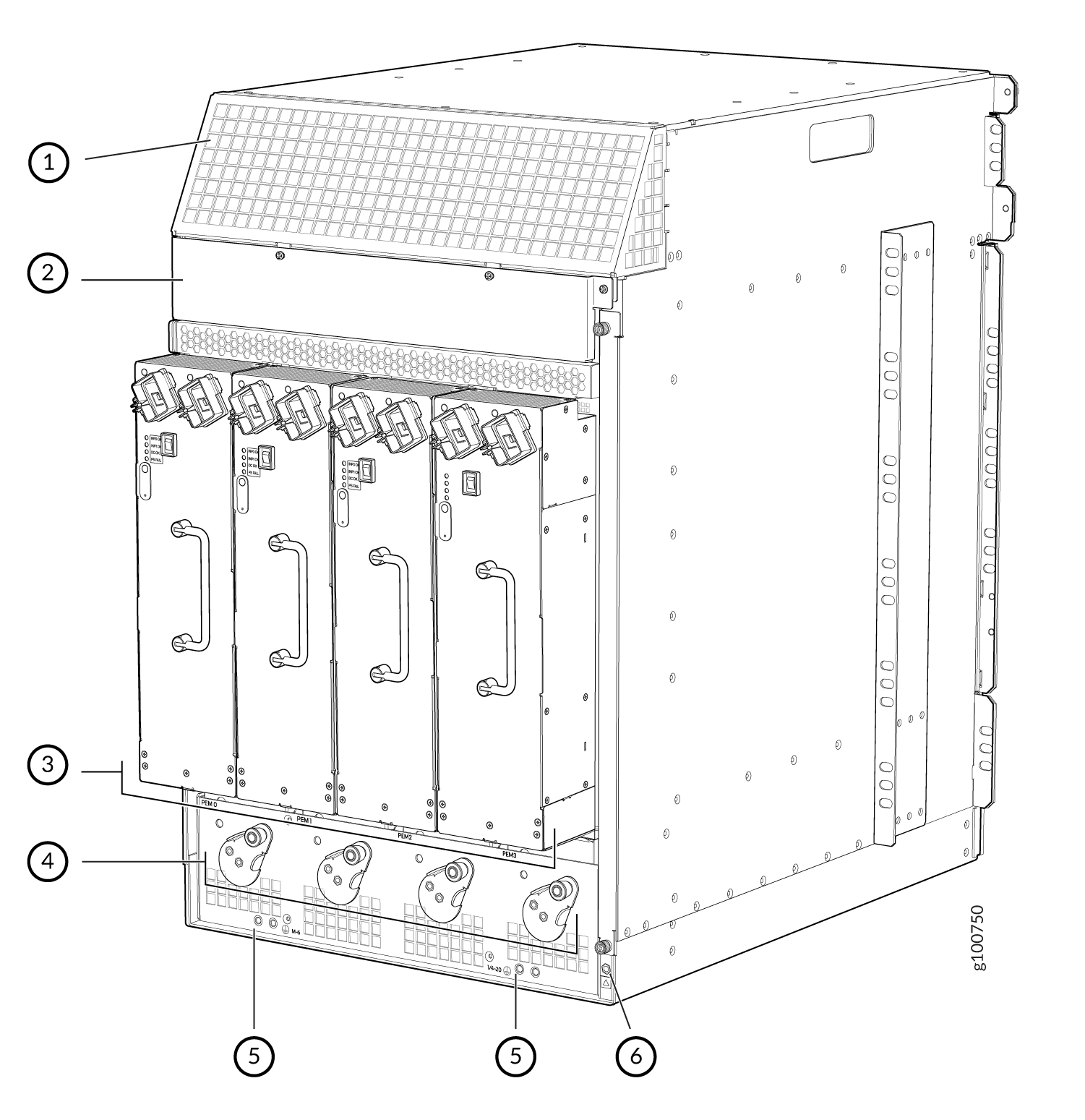 1—
1—Air exhaust
4—Power supply ejectors
2—Power distribution unit cover
5—Grounding points
3—High-capacity second-generation AC power supplies
6—ESD point
Note:The chassis is shown without the extended cable manager.
If necessary, pull the spring-loaded locking pin in the release lever away from the chassis and turn the release lever counterclockwise until it stops. Let go of the locking pin in the release lever. Ensure that the pin is seated inside the corresponding hole in the chassis.
-
On the power supply, rotate the metal cover away from the input mode switch to expose the switch.
-
Move the input mode switch to position 0 for one feed or position 1 for two feeds (see Figure 4).
Figure 4: MX960 AC Power Input Mode Switch Figure 5: Setting the Input Mode Switch (DIP Switch) on High-Capacity Second-Generation AC PSM
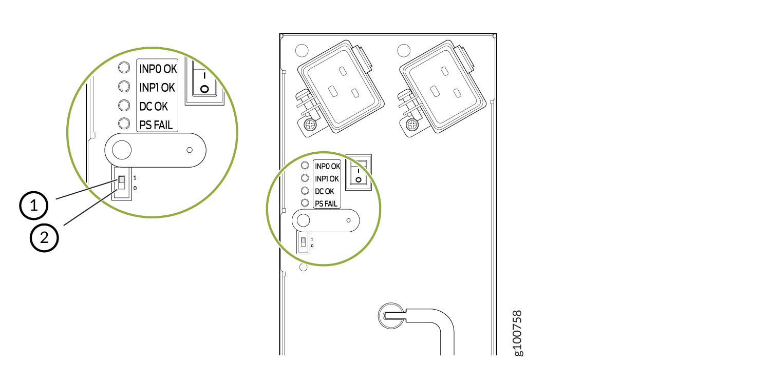 1—
1—Position 1 setting
2—Position 0 setting
CAUTION:Do not use a pencil, because fragments can break off and cause damage to the power supply.
-
Using both hands, slide the power supply straight into the chassis until the power supply is fully seated in the chassis slot. The power supply faceplate will protrude beyond the chassis.
The small tab on the metal housing that is controlled by the release lever must be inside of the corresponding slot at the bottom of the power supply (see Figure 4). This tab is used to pull the power supply down in the chassis slot, prior to removing the power supply.
-
While firmly pushing the handle on the power supply faceplate with one hand, use your other hand to pull the spring-loaded locking pin in the release lever away from the chassis and turn the release lever clockwise until it stops.
-
Let go of the locking pin in the release lever. Ensure that the pin is seated inside the corresponding hole in the chassis.
-
Attach the cover on the power distribution unit on the chassis for the high-capacity second-generation AC power supply.
-
Make sure the grounding cable is attached, see Grounding the MX960 Router.
-
Locate a power cord with the type of plug appropriate for your geographical location (see AC Power Cord Specifications for the MX960 Router).
-
Plug the power cord into the corresponding appliance inlet located in the chassis directly above the power supply. This is the recommend receptacle when using the power supply in one feed mode. If using the power supply in two-feed mode, plug the second power cord into the receptacle on the power supply. For the high-capacity second-generation PSM, use a screwdriver to tighten the screw on the retainer to prevent the AC cord from getting lose. See Figure 6
Figure 6: MX960 with One High-Capacity Second-Generation AC Power Feed Connected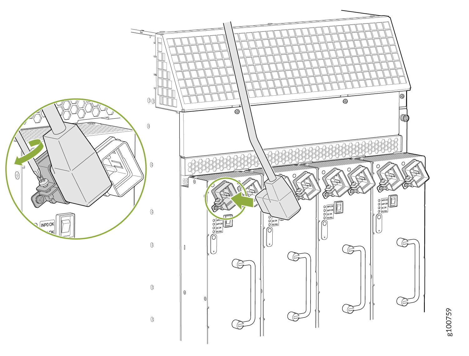 Note:
Note:Each power supply must be connected to a dedicated AC power feed and a dedicated customer site circuit breaker.
-
Dress the power cord appropriately. Verify that the power cord does not block the air exhaust and access to router components, and that they do not drape where people could trip on them.
-
Move the AC input switch above the power supply to the on (—) position. This is the only switch you have to turn on if you are using the power supply in one feed mode. If using the power supply in two-feed mode, move the power switch on the power supply to the on position. Remember to turn on both switches when operating the power supply in two-feed mode.
-
If the power supply is correctly installed and functioning normally, the AC1 OK, AC2 OK (two-feed mode only), and DC OK LEDs light steadily, and the PS FAIL LED is not lit. See Table 1.
-
Repeat steps 1-12 for installing power supplies in slots 1, 2, and 3, where present.
Table 1: MX960 or High-Capacity Second-Generation AC Power Supply LEDs Connected Inputs
DIP Switch Position
LEDs
INP0 OK
INP1 OK
DC OK
PS FAIL
INP0 connected, INP1 disconnected
0 (1 input)
Green
Off
Green
Off
INP0 disconnected, INP1 connected
0 (1 input)
Off
Green
Green
Off
INP0 connected, INP1 connected
0 (1 input)
Green
Green
Green
Off
INP0 connected, INP1 disconnected
1 (2 inputs)
Green
Off
Off
Red
INP0 disconnected, INP1 connected
1 (2 inputs)
Off
Green
Off
Red
INP0 connected, INP1 connected
1 (2 inputs)
Green
Green
Green
Off
To install and power on an MX960 universal (HVAC or HVDC) power supply, use the following procedure (see Figure 7).
-
Verify that the power switch on the power supply is in the off (O) position.
-
Ensure that the release lever below the empty power supply slot is locked in the counterclockwise position (see Figure 7).
Figure 7: MX960 with High-Voltage Second Generation Power Supplies Installed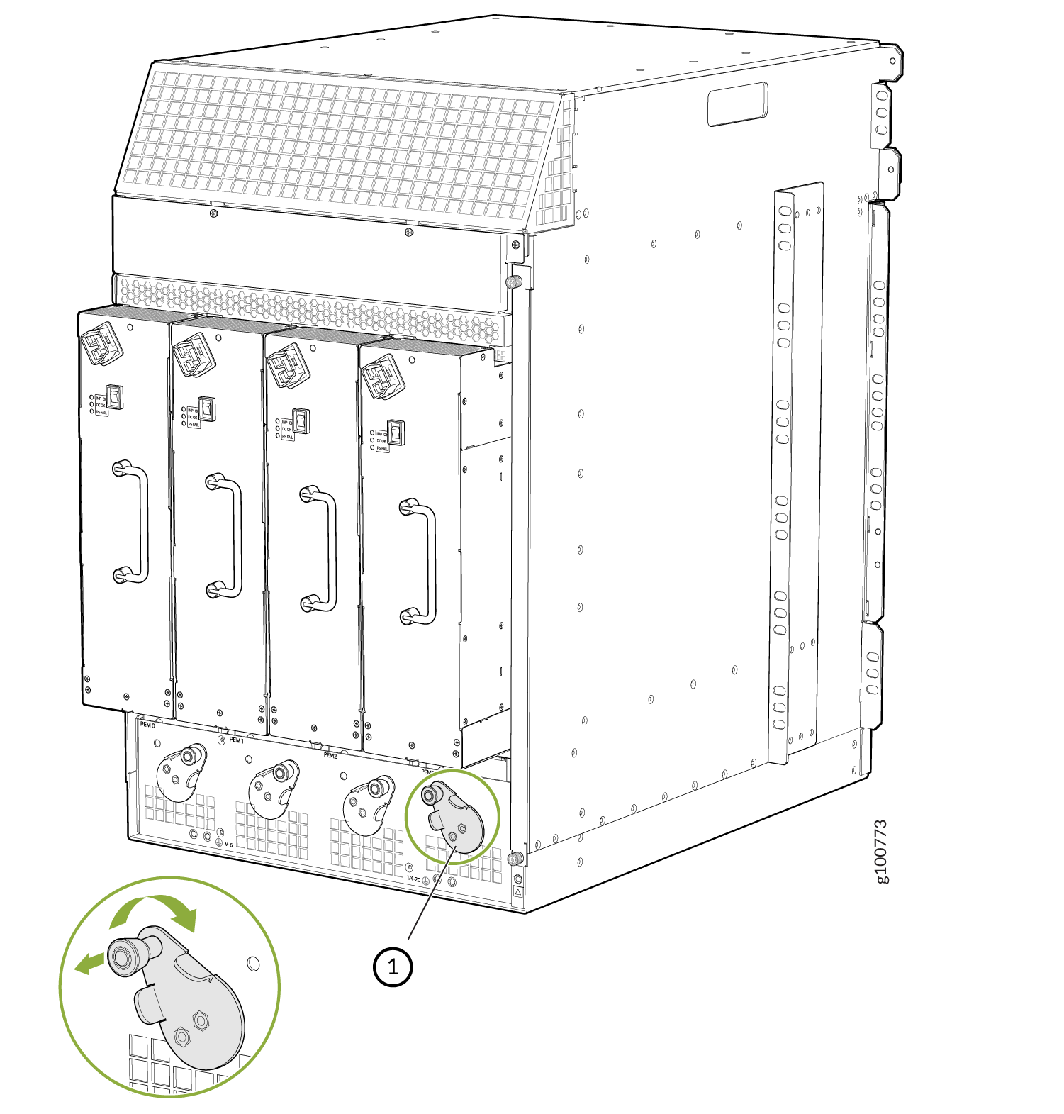 Note:
Note:The chassis is shown without the extended cable manager.
If necessary, pull the spring-loaded locking pin in the release lever away from the chassis and turn the release lever counterclockwise until it stops. Let go of the locking pin in the release lever. Ensure that the pin is seated inside the corresponding hole in the chassis.
-
On the power supply, rotate the metal cover away from the input mode switch to expose the switch.
-
Using both hands, slide the power supply straight into the chassis until the power supply is fully seated in the chassis slot. The power supply faceplate protrudes beyond the chassis.
The small tab on the metal housing that is controlled by the release lever must be inside of the corresponding slot at the bottom of the power supply (see Figure 7). This tab is used to pull the power supply down in the chassis slot, prior to removing the power supply.
-
While firmly pushing the handle on the power supply faceplate with one hand, use your other hand to pull the spring-loaded locking pin in the release lever away from the chassis and turn the release lever clockwise until it stops.
-
Let go of the locking pin in the release lever. Ensure that the pin is seated inside the corresponding hole in the chassis.
-
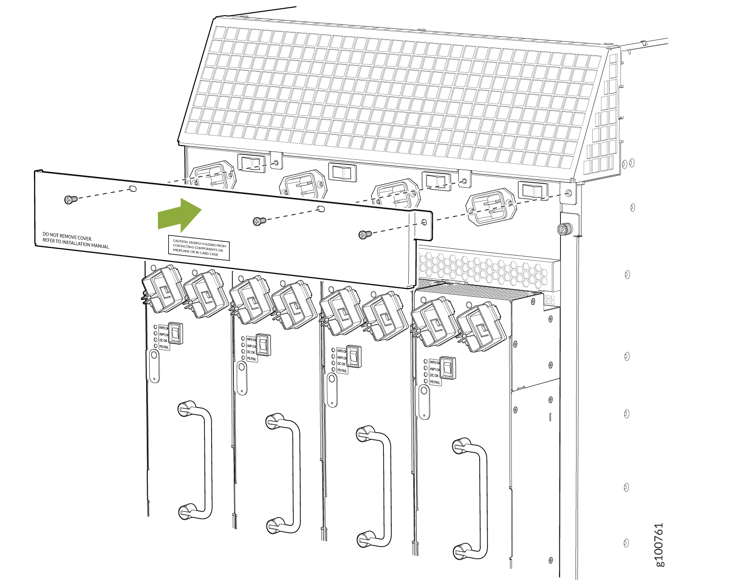
Make sure the cover is installed on the power distribution unit of the chassis, see Figure 8.
Figure 8: Installing the Cover on the Chassis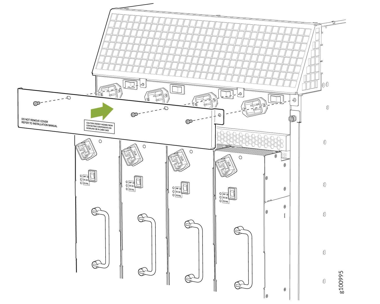
-
Make sure the grounding cable is attached, see Grounding the MX960 Router.
-
Locate a power cord with the type of plug appropriate for your geographical location (see High-Voltage Second-Generation Universal (MX960-PSM-HV) Power Cord Specifications for the MX960 Router).
-
Plug the power cord into the corresponding appliance inlet located in the chassis directly on the power supply.
Note:Each power supply must be connected to a dedicated power feed and a dedicated customer site circuit breaker.
Figure 9: MX960 with a High-Voltage Second-Generation (HVAC or HVDC) Power Feed Connected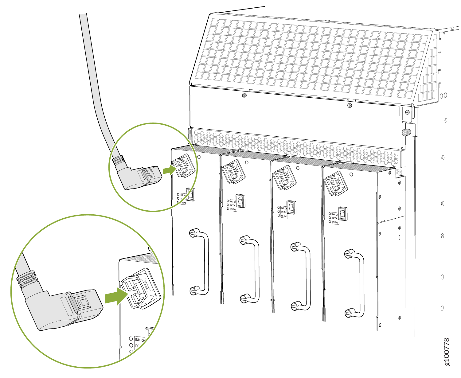
-
Dress the power cords appropriately. Verify that the power cord does not block the air exhaust and access to router components, and that they do not drape where people could trip on them.
-
Move the input switch above the power supply to the on (—) position.
Figure 10: MX960 Power Input Mode Switch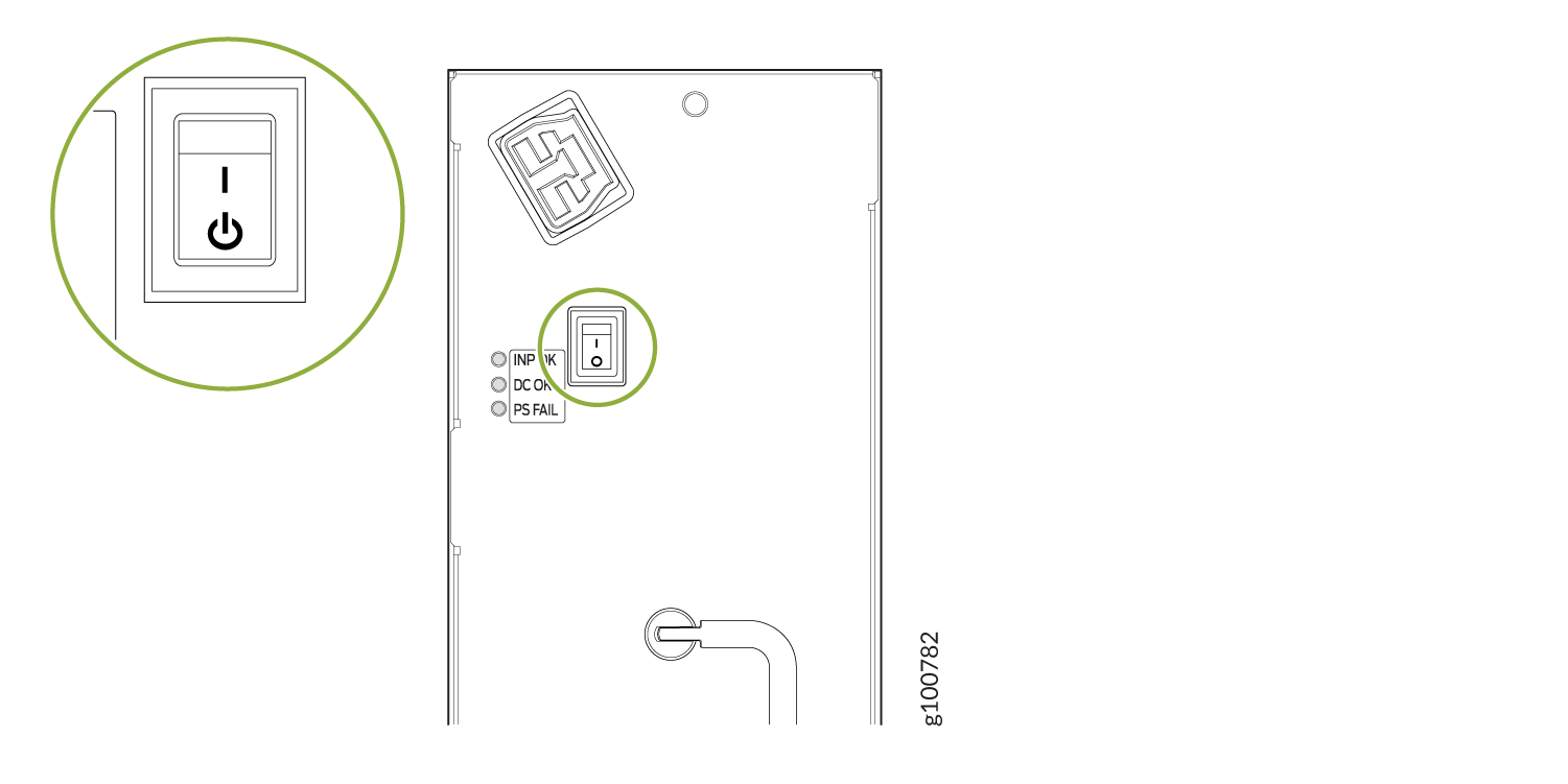
-
If the power supply is correctly installed and functioning normally, the INP OK, DC OK LEDs light steadily, and the PS FAIL LED is not lit.
-
Repeat steps 1-12 for installing power supplies in slots 1, 2, and 3, where required.
-
Install a blank panel over the power distribution modules, if available.