Converting from AC to DC Power Supplies on an MX960 Router
The conversion of an MX960 router from AC to DC or DC to AC should be performed with the system completely powered off. A system cannot operate with a mix of AC and DC power supplies. This procedure assumes conversion from normal-capacity power supplies to high-capacity power supplies.
Remove MX960 normal-capacity AC power supplies for power supplies in slots 0, 1, 2, 3 where present. All power supplies should be removed before proceeding with the installation of the DC power supplies. To convert from AC to DC, use the following procedures.
Use the following procedures to install the MX960 high-capacity DC power supplies for power supply in slots 0, 1, 2, and 3, where present.
Use the following procedures to install the MX960 high capacity DC power supplies or install the high-voltage second-generation universal (HVAC/HVDC) power supplies for power supply in slots 0, 1, 2, 3 where present.
To remove a normal-capacity AC power supply (see Figure 1):
-
Repeat steps 1-6 for power supplies in slot 1, 2, 3 where
present.
Figure 1: Removing an MX960 AC Power Supply
 Note:
Note:The chassis is shown without the extended cable manager.
To install an MX960 high-capacity DC power supply:
-
Verify that the power switch on the power supply is in the off (O) position.
-
On the power supply, rotate the metal cover away from the input mode switch to expose the switch.
-
Move the input mode switch to position 0 for one feed or position 1 for two feeds (see Figure 2).
Note:For a fully redundant configuration in two-feed mode, eight feeds are required. For a nonredundant configuration, four feeds are required.
Figure 2: MX960 with High-Capacity DC Power Supplies Installed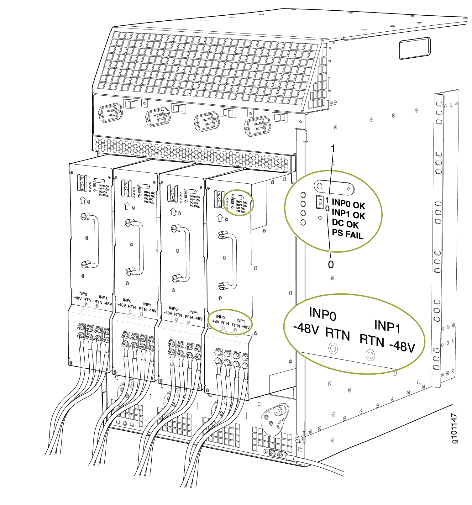 Note:
Note:The chassis is shown without the extended cable manager.
CAUTION:Do not use a pencil, because fragments can break off and cause damage to the power supply.
-
Ensure that the voltage across the DC power source cable leads is 0 V and that there is no chance that the cable leads might become active during installation.
-
Ensure that the release lever below the empty power supply slot is locked in the counterclockwise position.
If necessary, pull the spring-loaded locking pin in the release lever away from the chassis and turn the release lever counterclockwise until it stops. Let go of the locking pin in the release lever. Ensure that the pin is seated inside the corresponding hole in the chassis.
-
Using both hands, slide the power supply straight into the chassis until the power supply is fully seated in the chassis slot.
The small tab on the metal housing that is controlled by the release lever must be inside of the corresponding slot at the bottom of the power supply. This tab is used to pull the power supply down in the chassis slot, prior to removing the power supply.
-
While firmly pushing the handle on the power supply faceplate with one hand, use your other hand to pull the spring-loaded locking pin in the release lever away from the chassis and turn the release lever clockwise until it stops.
-
Let go of the locking pin in the release lever. Ensure that the pin is seated inside the corresponding hole in the chassis.
-
Remove the cover protecting the terminal studs on the faceplate.
-
Remove the nut and washer from each of the terminal studs.
-
Secure each power cable lug to the terminal studs, first with the split washer, then with the nut. Apply between 23 lb-in. (2.6 Nm) and 25 lb-in. (2.8 Nm) of torque to each nut. Do not overtighten the nut. (Use a 7/16-in. [11-mm] torque-controlled driver or socket wrench.)
-
On INPUT 0, attach the positive (+) DC source power cable lug to the RTN (return) terminal as shown in Figure 2. Repeat this step for INPUT 1 if using two feeds.
-
On INPUT 0 attach the negative (–) DC source power cable lug to the -48V (input) terminal. Repeat this step for INPUT 1 if using two feeds.if using two feeds.
CAUTION:Ensure that each power cable lug seats flush against the surface of the terminal block as you are tightening the nuts. Ensure that each nut is properly threaded onto the terminal stud. The nut should be able to spin freely with your fingers when it is first placed onto the terminal stud. Applying installation torque to the nut when improperly threaded may result in damage to the terminal stud.
CAUTION:The maximum torque rating of the terminal studs on the DC power supply is 36 lb-in. (4.0 Nm). The terminal studs may be damaged if excessive torque is applied. Use only a torque-controlled driver or socket wrench to tighten nuts on the DC power supply terminal studs.
Note:INPUT 0 for all four power supplies must be powered by dedicated power feeds derived from feed A, and INPUT 1 for all four power supplies must be powered by dedicated power feeds derived from feed B. This configuration provides the commonly deployed A/B feed redundancy for the system. For information about connecting to DC power sources, see Electrical Specifications for the MX960 DC Power Supply.
-
-
Verify that the power cabling is correct, that the cables are not touching, and that they do not block access to router components or drape where people could trip on them.
-
Replace the clear plastic cover over the terminal studs on the faceplate.
-
Switch on the dedicated customer site circuit breaker.
-
Verify that the INPUT 0 OK or INPUT 1 OK LEDs on the power supply are lit green steadily. If using two feeds, verify that both INPUT 0 OK and INPUT 1 OK LEDs on the power supply are lit steadily. The INPUT OK will be lit amber if that input’s voltage is in reverse polarity. Check the polarity of the power cables to fix the condition (see Figure 3 and Table 1.
-
Move the switch to the on (|) position.
-
Verify that the DC OK LED is lit green steadily. See Table 1 for information on MX960 high-capacity DC LEDs.
Table 1: MX960 High-Capacity DC Power Supply LEDs Connected Inputs
DIP Switch Position
LEDs
INP-0 OK
INP-1 OK
DC OK
PS FAIL
INP0 connected, INP1 disconnected
0 (1 input)
Green
Off
Green
Off
INP0 disconnected, INP1 connected
Off
Green
Green
Off
INP0 connected, INP1 connected
Green
Green
Green
Off
INP0 connected, INP1 disconnected
1 (2 inputs)
Green
Off
Off
Red
INP0 disconnected, INP1 connected
Off
Green
Off
Red
INP0 connected, INP1 connected
Green
Green
Green
Off
-
Repeat steps 1-17 for installing power supplies in slots 1, 2, and 3, where present.
Figure 3: MX960 DC High-Capacity Power Supply Front View
-
Install a blank panel over the power distribution modules, if available.
To install and power on an MX960 universal (HVAC or HVDC) power supply, use the following procedure (see Figure 4).
-
Verify that the power switch on the power supply is in the off (O) position.
-
Ensure that the release lever below the empty power supply slot is locked in the counterclockwise position (see Figure 4).
Figure 4: MX960 with High-Voltage Second Generation Power Supplies Installed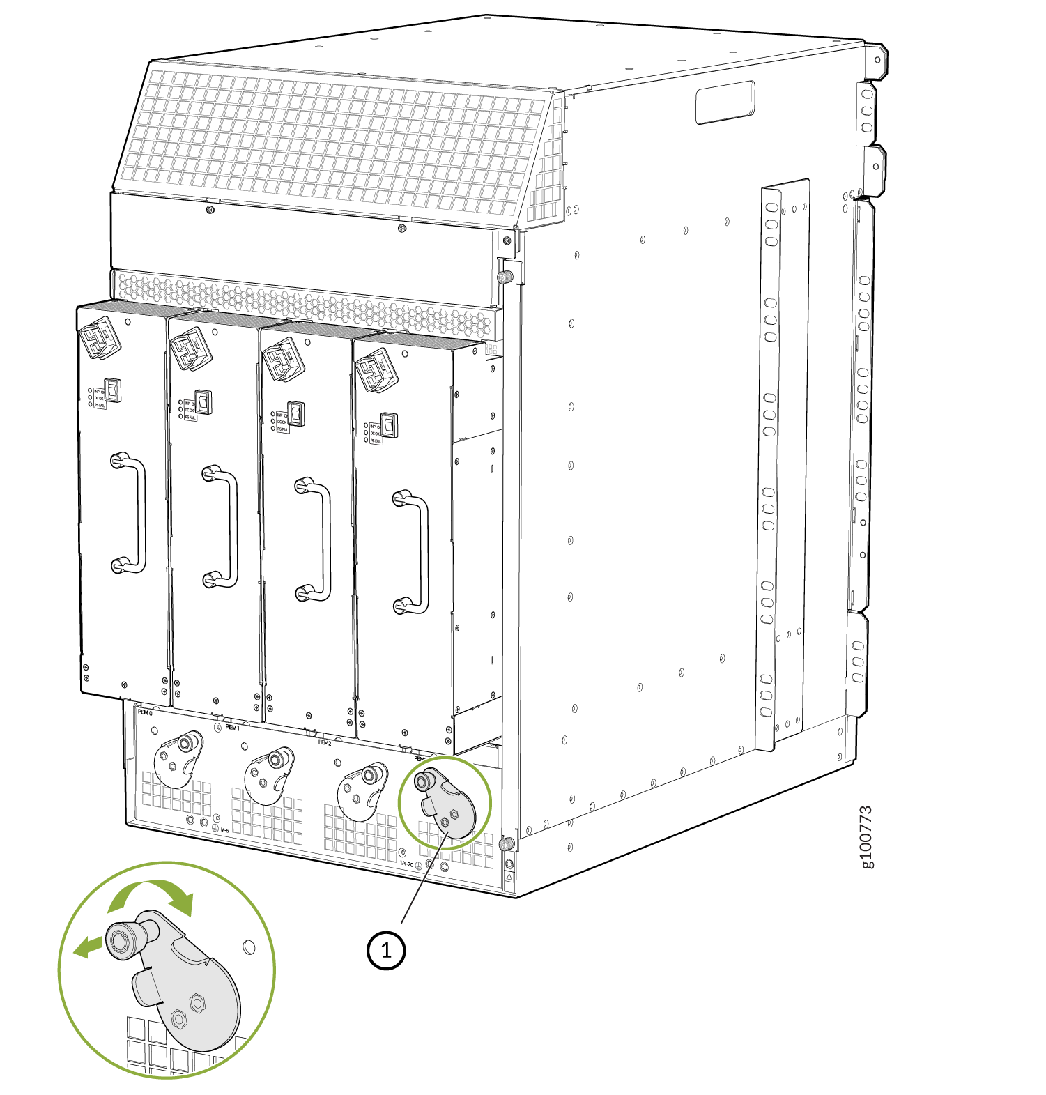 Note:
Note:The chassis is shown without the extended cable manager.
If necessary, pull the spring-loaded locking pin in the release lever away from the chassis and turn the release lever counterclockwise until it stops. Let go of the locking pin in the release lever. Ensure that the pin is seated inside the corresponding hole in the chassis.
-
On the power supply, rotate the metal cover away from the input mode switch to expose the switch.
-
Using both hands, slide the power supply straight into the chassis until the power supply is fully seated in the chassis slot. The power supply faceplate protrudes beyond the chassis.
The small tab on the metal housing that is controlled by the release lever must be inside of the corresponding slot at the bottom of the power supply (see Figure 4). This tab is used to pull the power supply down in the chassis slot, prior to removing the power supply.
-
While firmly pushing the handle on the power supply faceplate with one hand, use your other hand to pull the spring-loaded locking pin in the release lever away from the chassis and turn the release lever clockwise until it stops.
-
Let go of the locking pin in the release lever. Ensure that the pin is seated inside the corresponding hole in the chassis.
-
Make sure the cover is installed on the power distribution unit of the chassis, see Figure 5.
Figure 5: Installing the Cover on the Chassis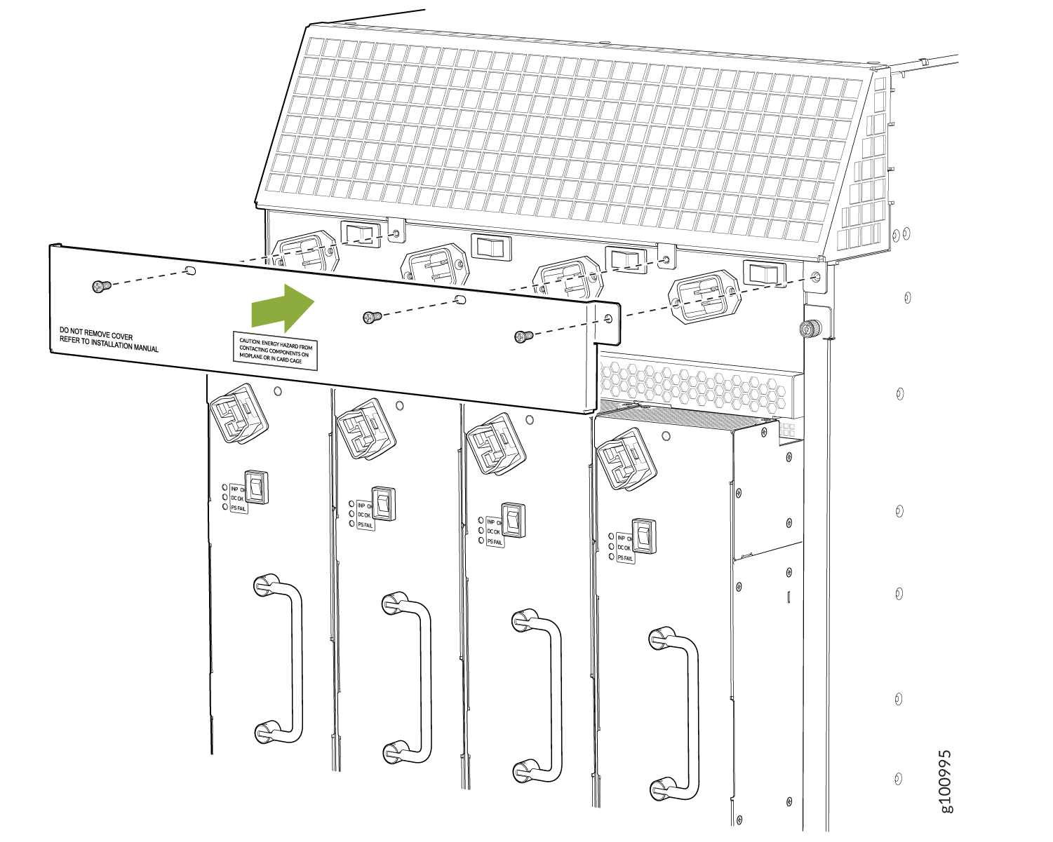
-
Make sure the grounding cable is attached, see Grounding the MX960 Router.
-
Locate a power cord with the type of plug appropriate for your geographical location (see High-Voltage Second-Generation Universal (MX960-PSM-HV) Power Cord Specifications for the MX960 Router).
-
Plug the power cord into the corresponding appliance inlet located in the chassis directly on the power supply.
Note:Each power supply must be connected to a dedicated power feed and a dedicated customer site circuit breaker.
Figure 6: MX960 with a High-Voltage Second-Generation (HVAC or HVDC) Power Feed Connected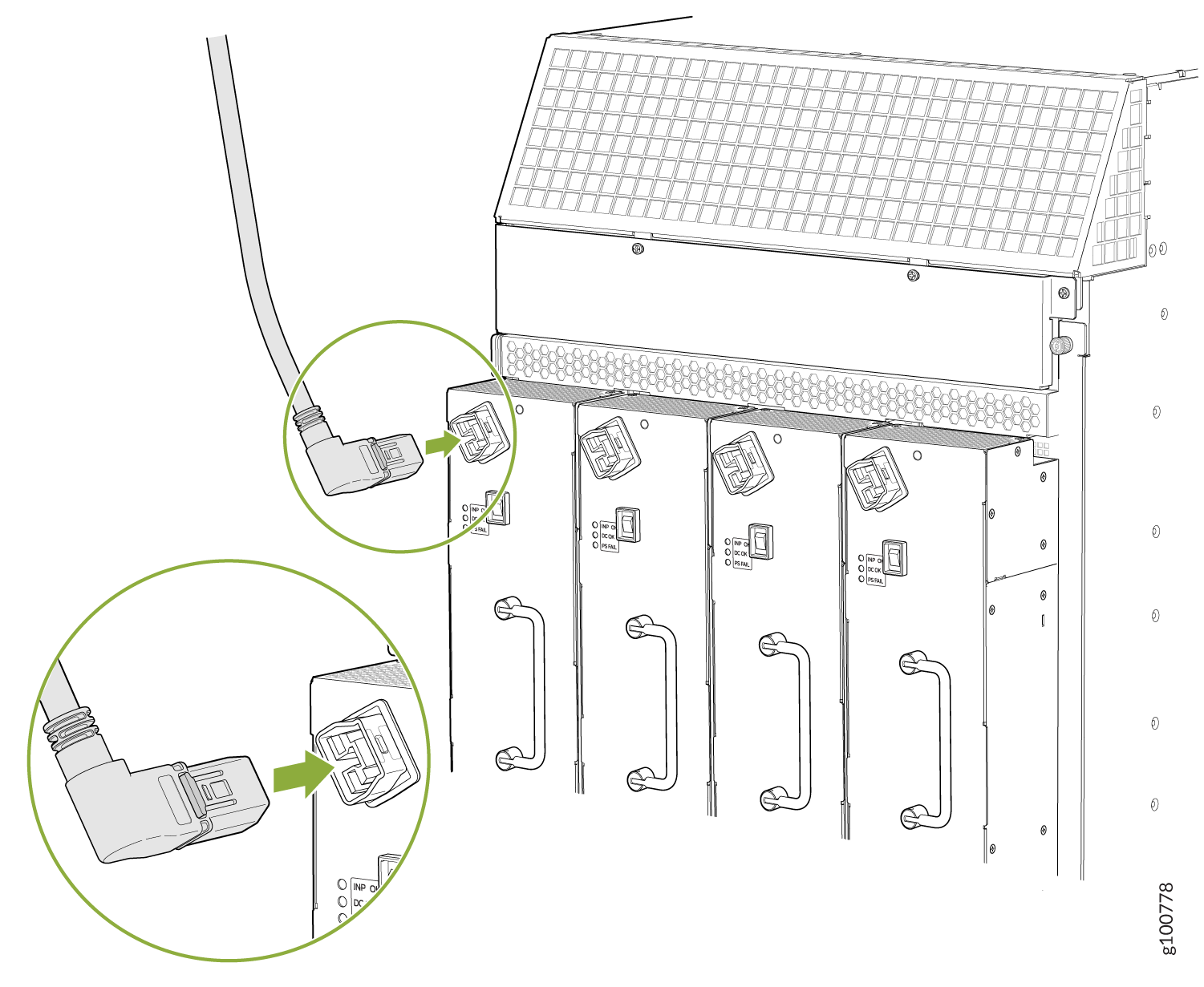
-
Dress the power cords appropriately. Verify that the power cord does not block the air exhaust and access to router components, and that they do not drape where people could trip on them.
-
Move the input switch above the power supply to the on (—) position.
Figure 7: MX960 Power Input Mode Switch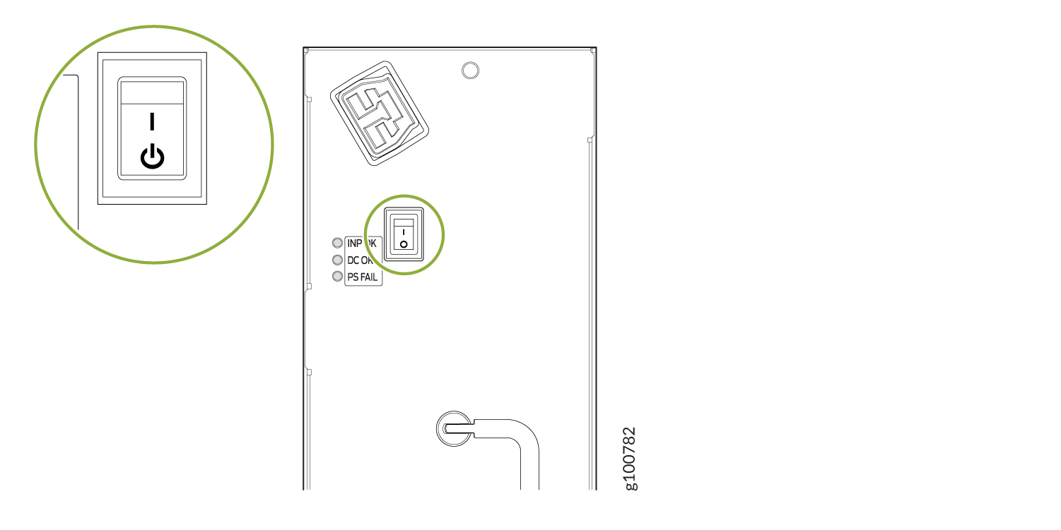
-
If the power supply is correctly installed and functioning normally, the INP OK, DC OK LEDs light steadily, and the PS FAIL LED is not lit.
-
Repeat steps 1-12 for installing power supplies in slots 1, 2, and 3, where required.
-
Install a blank panel over the power distribution modules, if available.