MX960 Acoustic Cover Installation Instructions
This document describes how to remove and replace the acoustic noise covers on a Juniper Networks MX960 Universal Routing Platform. The upper fan tray cover and interface module cover make up the acoustic noise components. The two acoustic covers are designed to reduce the system sound level to comply with the Network Equipment Building System (NEBS). The covers and all associated mounting hardware are available as an optional upgrade kit.
Tools required:
-
Number 2 Phillips screwdriver
-
7/16” wrench
|
Component |
Quantity |
|---|---|
|
12–24 1 1/4 in. screws |
4 |
|
12–24 nylon lock nuts |
4 |
|
Star washer |
1 |
|
Card cage cover mounting bracket |
2 |
|
Upper fan tray cover |
1 |
|
DPC Card cage cove |
1 |
Installing the Upper Fan Tray Cover
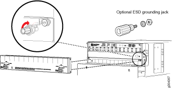
The upper fan tray cover is installed below the craft interface and covers the upper fan tray. To install the upper fan tray cover, use the following procedure (see Figure 1).
The upper fan tray cover obstructs the existing electrostatic discharge (ESD) jack located above the upper fan tray on the front of the chassis. A second ESD jack is located on the lower rear of the chassis. An optional ESD jack has been provided in the installation kit and may be installed in an available rack mounting hole. Ensure that the mounting surface is conductive and free of paint. Secure the optional ESD jack with the star washer and nut provided in the installation kit.
-
Rotate the latch knobs clockwise, and hand tighten them
until they are secure.
Figure 1: Upper Fan Tray Cover and Optional ESD Grounding Jack
Installing the Interface Module Cage Cover Center-Mount Brackets
The interface module cage cover is installed directly over the interface module cage. The installation of the brackets depends on whether the router is center or front mounted.
To install the center-mount brackets for the interface module cage cover on routers that are center mounted, use the following procedure (see Figure 2).
- Locate the tab on the rear surface of the mounting bracket.
- Place the rear surface of the bracket against the mounting flange. Vertical alignment is correct when the tab rests on top of the flange.
- Locate the highest available mounting hole on the bracket and insert the first screw through the bracket and flange. Secure it with a nylock nut.
- Locate the lowest available mounting hole on the bracket and insert the second screw through the bracket and flange. Secure it with a nylock nut.
- Use a screwdriver and a wrench to hand tighten the screws and nylock nuts. Do not overtighten the screws. Overtightening may cause damage to the plastic bracket.
- Repeat the above steps with the second bracket.
Installing the Interface Module Cage Cover Front-Mount Brackets
To install the brackets for the interface module cage cover on routers that are front-mounted, use the following procedure:
- Locate the tab on the rear surface of the mounting bracket.
- Place the rear surface of the bracket against the mounting flange. Vertical alignment is correct when the tab rests on top of the flange.
- Locate the highest available mounting hole on the bracket and insert the first screw through the bracket and threaded rack flange.
- Locate the lowest available mounting hole on the bracket and insert the second screw through the bracket and threaded rack flange.
- Use a screwdriver to hand tighten the screw . Do not overtighten the screws; overtightening may cause damage to the plastic bracket.
- Repeat the above steps with the second bracket.
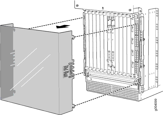
Installing the Interface Module Cage Cover
To install the interface module cage cover, use the following procedure (see Figure 2).
- Look through the front of the cover and align the four hooks on either side of the acoustic cover with the rail slots on the outside of the card cage.
- Slide the cover into the rail slots.
- Gently push the cover down to secure it in place.
Removing the Upper Fan Tray Cover
The upper fan tray cover is installed below the craft interface and covers the upper fan tray. To remove the upper fan tray cover, use the following procedure (see Figure 1).
- Rotate the latch knobs counterclockwise until the cover is released or until the knobs stop turning.
- Remove the cover.
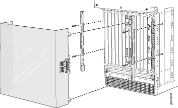
Removing the Interface Module Cage Cover
To remove the interface module cage cover, use the following procedure (see Figure 3).
-
Slide the cover up until it stops; then pull the cover
toward you to remove.
Figure 3: Removing the Interface Module Cage Cover