MX304 Power System
The MX304 routers support AC, DC, high-voltage alternating current (HVAC) and high-voltage direct current (HVDC) by offering the following power supplies:
-
JNP-PWR2200-AC
-
JNP-PWR2200-DC
-
JNP-PWR2200-HV
The MX304 uses either AC, DC, or HVAC/DC power supply modules. The router contains two power supplies at the rear of the chassis in slots PSM0 through PSM1. The AC, DC, or HVAC/DC power supplies directly plug into the midplane and are located symmetrically on the left side of the chassis for better thermal management. Each power supply has a handle, an ejection lever, and a status LED. The power supplies connect to the power adapter board, which distributes the different output voltages produced by the power supplies to the router components, depending on their voltage requirements. A minimum of one power supply is required for non-redundant operation. If one power supply in a redundant configuration fails, the second power supply assumes the entire electrical load without interruption. See MX304 Component Redundancy for more information on power redundancy supported on the AC and DC powered router. Each power supply is cooled by its own internal cooling system. The chassis operates in 1 + 1 PSU redundancy mode. Feed redundancy is not supported.
All of the power supplies are hot-insertable and hot-removable, field-replaceable units (FRUs). The router ships with two power supplies labeled PSU 0 through PSU 1 (top to bottom) in the rear of the chassis. Don't keep the power supply slot empty.
Do not mix AC and DC power supplies in the same chassis. AC and HVAC can coexist in the same chassis during the hot-swap of AC for HVAC. Do not mix AC and HVAC power supplies in a running environment.
MX304 AC Power System Description
The MX304 uses either AC, DC, or HVAC/DC power supply modules (see Figure 1 ).
Redundant power supplies are hot-removable and hot-insertable. When you remove a power supply from a router that uses only one power supply, the router might shut down depending on your configuration.
Do not mix AC, DC, or HVAC/DC power supplies in the same chassis.
Before you begin installing the router, ensure that a licensed electrician has attached an appropriate grounding lug to the grounding cable that you supply. Using a grounding cable with an incorrectly attached lug can damage the router.
You can prevent AC power cables from being exposed to hot air exhaust by always routing the power cables away from the fan trays and power supplies.
Each inlet requires a dedicated AC power feed and a dedicated customer-site circuit breaker. We recommend that you use a minimum 16 A customer-site circuit breaker, or as required by local code.
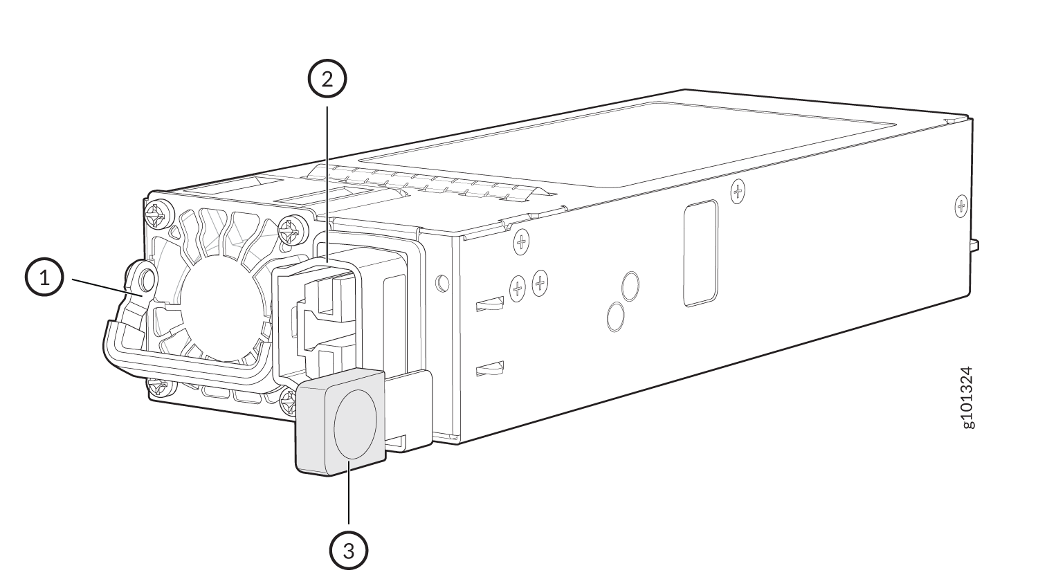
Each AC power supply weighs approximately 2.42 lb (1.1 kg) and consists of a handle, an ejector lever, an AC appliance inlet, a fan, and an LED to monitor the status of the power supply. Figure 1 shows the power supply. Each inlet requires a dedicated AC power feed and a dedicated customer-site circuit breaker.
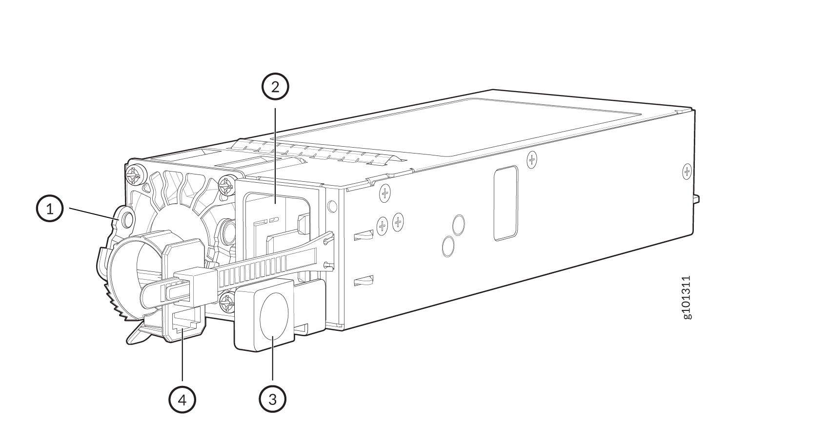
1 — Handle | 3 — Ejector lever |
2 — AC inlet plug | 4 — Power cord retainer |
MX304 AC Power Supply Module LEDs
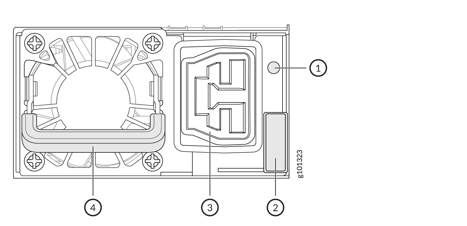
Figure 2 shows the AC power supplies components along with the status LED.
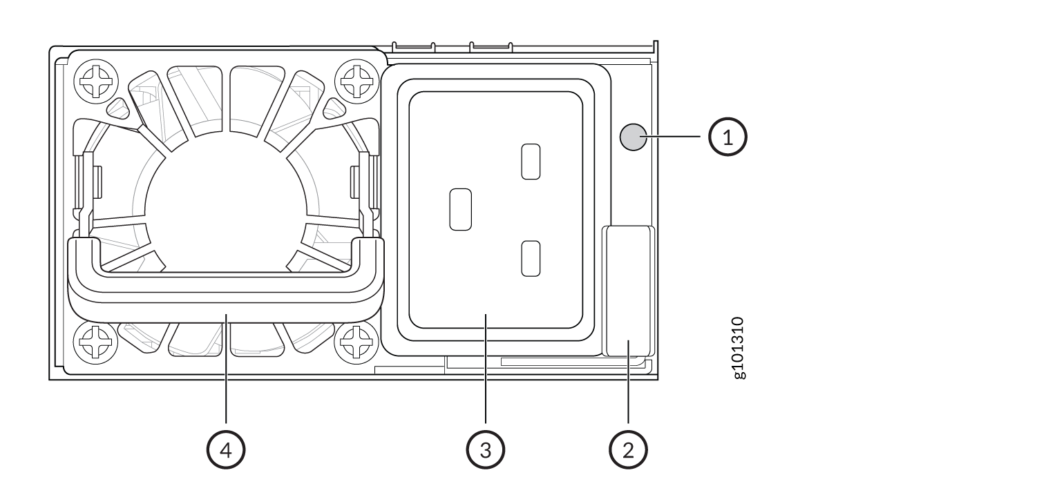
1 — Status LED | 3 — AC inlet plug |
2 — Ejector lever | 4 — Handle |
|
Label |
Color |
State |
Description |
|---|---|---|---|
|
STATUS |
Green |
Blinking (1Hz) |
Power supply is in standby state |
|
Blinking (2Hz) |
Power supply firmware is updating | ||
|
On steadily |
Output is ON and OK |
||
|
Amber |
On steadily Blinking (1Hz) |
Power supply is faulty and not functioning normally; failure, overcurrent, short circuit, over voltage, fan failure, or over temperature AC cord is unplugged or AC power is lost |
|
|
Power supply warning events where the power supply continues to operate; high temperature or high power |
|||
| Off | No AC power to all the power supply |
See Also
MX304 DC Power System Description
MX304 DC Power System Description
Each DC power supply weighs approximately 2.42 lb (1.1 kg) and consists of a handle, an ejector lever, a status LED, and a terminal block that provides a single DC input (–48/–60 VDC and return). The DC power supply requires a dedicated customer-site circuit breaker. We recommend that you use a dedicated customer-site circuit breaker rated for 60 A (60 VDC), or as required by local code.
Do not mix AC, DC, or HVAC/DC power supplies in the same chassis.
Figure 3 shows the power supply.
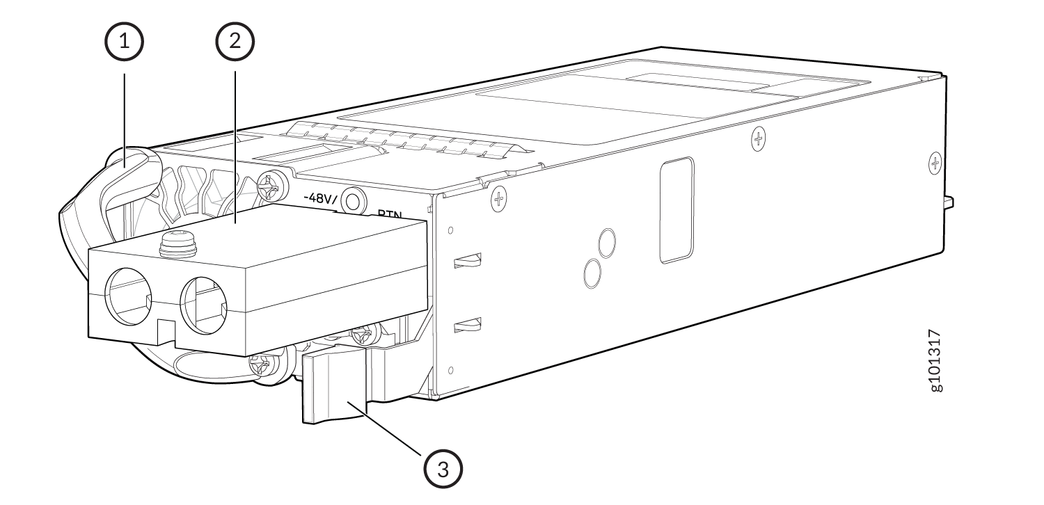
1 — Handle | 3 — Ejector lever |
2 — DC inlet cable lug point |
MX304 DC Power Supply Module LEDs
Figure 4 shows the DC power supplies components along with the status LED.
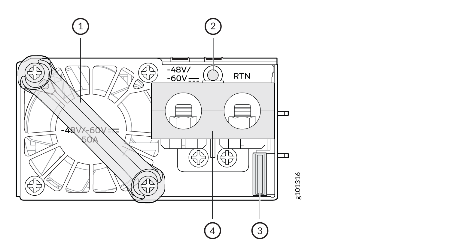
1 — Handle | 3 — Ejector lever |
2 — Status LED | 4 — DC inlet cable lug point |
|
Label |
Color |
State |
Description |
|---|---|---|---|
|
STATUS |
Green |
Blinking (1Hz) |
Power supply is in standby state. |
|
Blinking (2Hz) |
Power supply firmware is updating. | ||
|
On steadily |
Output is ON and OK. |
||
|
Amber |
On steadily |
Power supply is faulty and not functioning normally; failure, overcurrent, short circuit, over voltage, fan failure, or over temperature. DC cord is unplugged or DC power is lost. |
|
|
Blinking (1Hz) |
Power supply warning events where the power supply continues to operate; high temperature or high power. |
||
| Off | No DC power to both the power supplies. |
MX304 High-Voltage AC/DC Universal System Power Description
The MX304 uses either AC, DC, or HVAC/DC power supply modules (see Figure 5).
Redundant power supplies are hot-removable and hot-insertable. When you remove a power supply from a router that uses only one power supply, the router might shut down depending on your configuration.
Do not mix AC, DC, HVAC/DC power supplies in the same chassis.
Each HVAC/DC power supply weighs approximately 2.42 lb (1.1 kg) and consists of a handle, an ejector lever, an AC anderson inlet, a fan, and an LED to monitor the status of the power supply. Figure 5 shows the power supply.
Each inlet requires a dedicated HVAC or HVDC power feed and a dedicated customer-site circuit breaker. We recommend that you use a minimum 16-A customer-site circuit breaker, or as required by local code.
The router is a pluggable type A equipment installed in a restricted-access location. It has a separate protective earthing terminal (sized for M6 hex screws) provided on the chassis in addition to the grounding pin of the power supply cord. This separate protective earthing terminal must be permanently connected to earth.
1 — Handle | 3 — Ejector lever |
2 — AC/DC inlet plug |
MX304 High-Voltage Universal Power Supply Module LEDs
Figure 6 shows the HVAC/HVDC power supplies components along with the status LED.
1 — Status LED | 3 — HVAC/DC inlet |
2 — Ejector lever | 4 — Handle |
|
Label |
Color |
State |
Description |
|---|---|---|---|
|
STATUS |
Green |
Blinking (1Hz) |
Power supply is in standby state. |
|
Blinking (2Hz) |
Power supply firmware is updating. | ||
|
On steadily |
Output ON and OK. |
||
|
Amber |
On steadily |
Faulty and not functioning normally; failure, overcurrent, short circuit, over voltage, fan failure, or over temperature. HVAC/HVDC cord unplugged or power lost. |
|
|
Blinking (1Hz) |
Power supply warning events where the power supply continues to operate; high temperature or high power. |
||
| Off | No HVAC or HVDC power to both the power supplies. |