ON THIS PAGE
MX301 Power System
The MX301 power system includes AC, DC, and HVAC/DC power supply units (PSUs) with related power cords and cables. The PSUs operate within certain ranges and are equipped with status indicator LEDs.
The MX301 uses two 850-W AC, DC, or HVAC/DC PSUs with support for 1+1 redundancy. The PSUs are preinstalled at the factory. The PSUs in the MX301 are hot-insertable and hot-removable field-replaceable units (FRUs). If one PSU fails, you can replace it without powering off or disrupting the routing function. The other PSU balances the electrical load without interruption. A fan in each PSU provides cooling. The PSUs are located at the rear of the MX301.
The MX301 supports the following PSUs:
| AC | DC | HVAC/DC |
|---|---|---|
Avoid mixing:
-
AC and DC PSUs in the same chassis.
-
PSUs with different ratings in the same chassis.
-
PSUs with different airflow directions in the same chassis.
-
PSUs and fan modules with different airflow directions in the same chassis.
The maximum and typical power consumption of the system depends on the type of power supply.
JPSU-850W-AC-AFO
- JPSU-850W-AC-AFO
- JPSU-850W-AC-AFO Specifications
- JPSU-850W-AC-AFO LEDs
- Supported AC Power Cords on the JPSU-850W-AC-AFO
JPSU-850W-AC-AFO
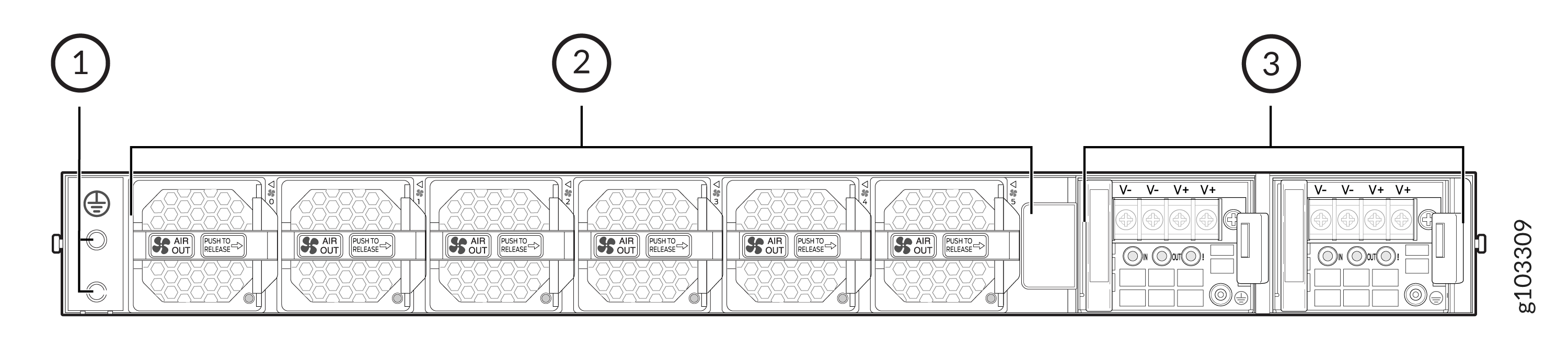
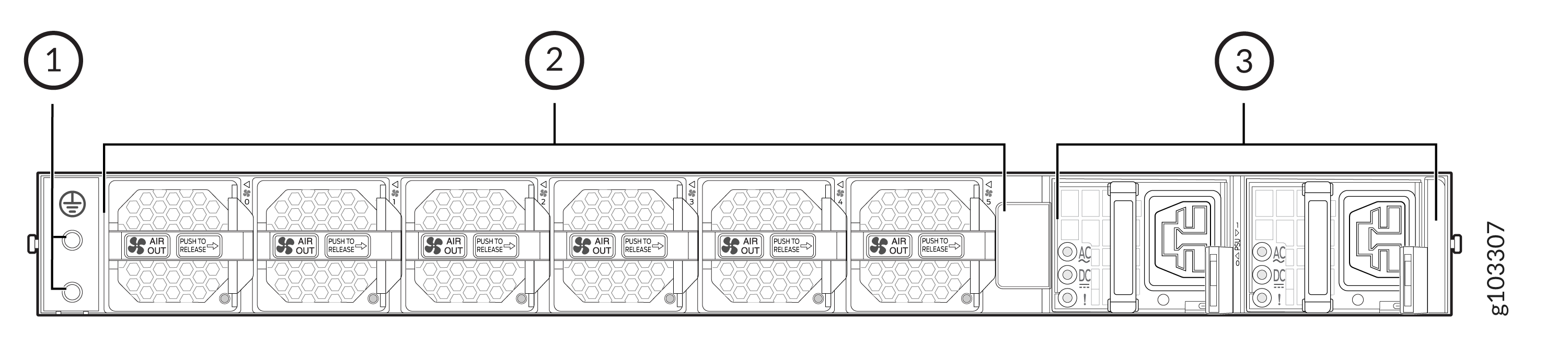
Figure 1 shows the location of the PSUs on the back panel.
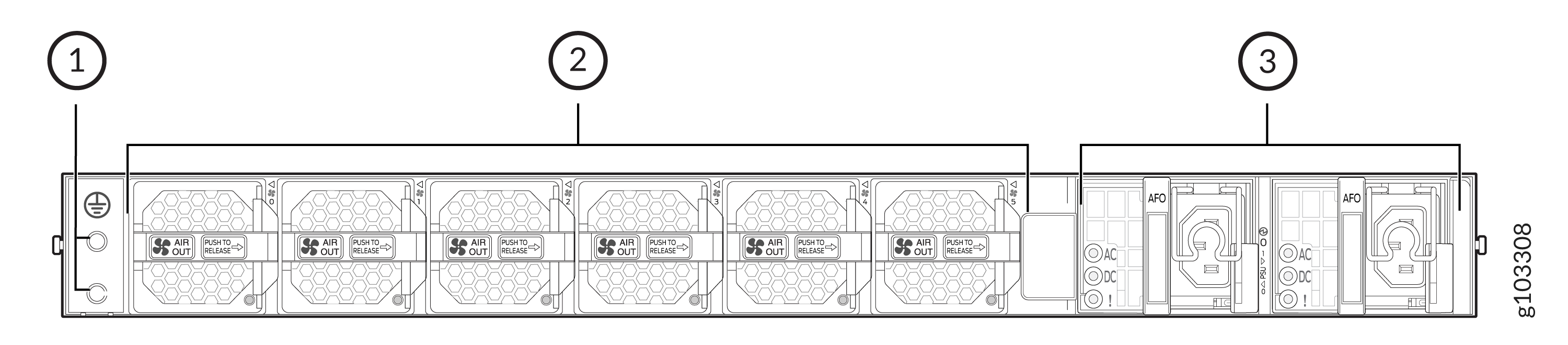
1 — Grounding point | 3 — AC PSU (2 units) |
2 — Fan modules (6 units) |
Figure 2 shows the components on the JPSU-850-AC-AFO PSU.
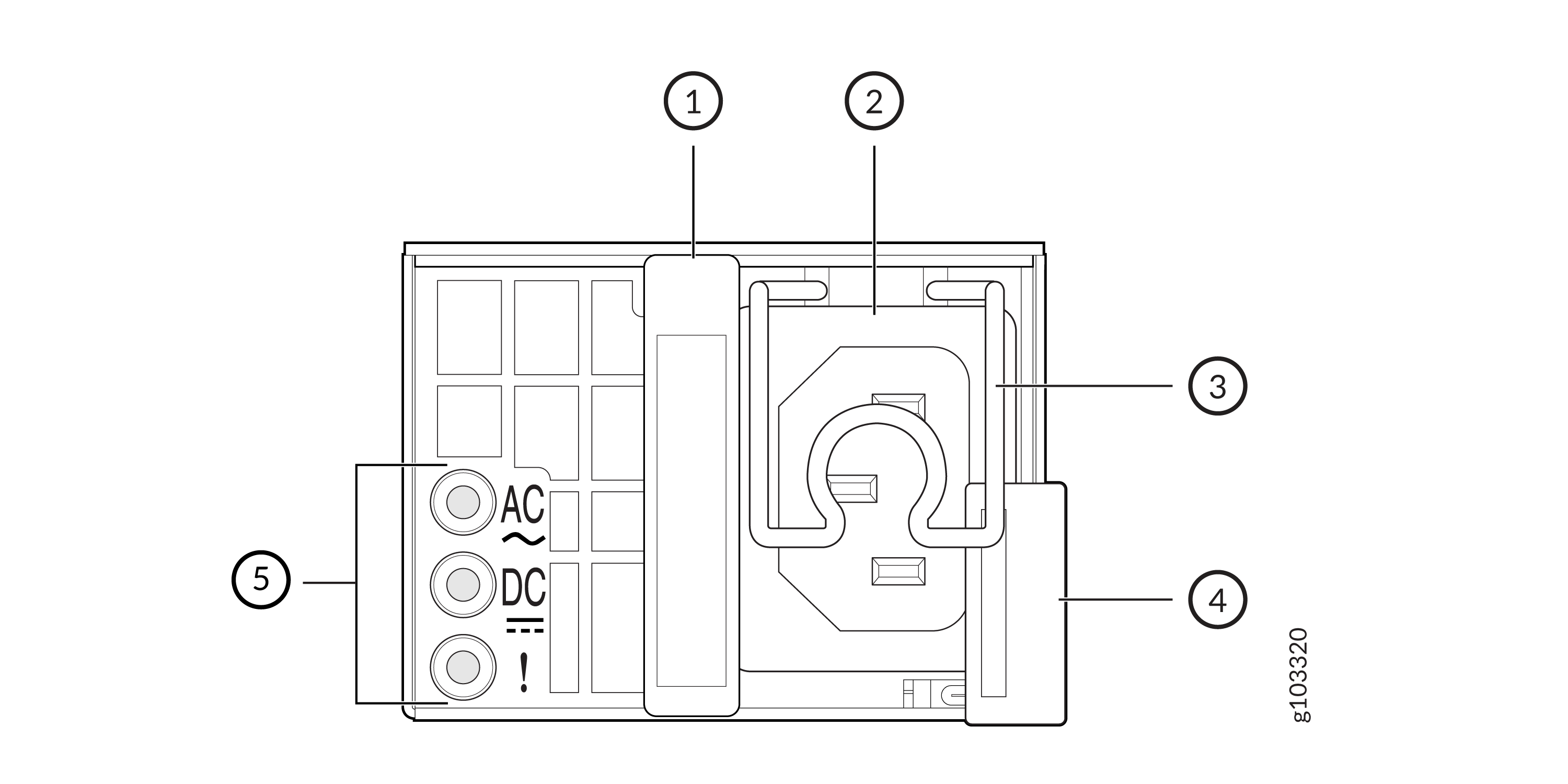
Table 1 describes the components on the JPSU-850W-AC-AFO.
| Callout | Name |
|---|---|
|
1 |
Handle |
|
2 |
Power inlet |
|
3 |
Power cord retainer |
|
4 |
Release latch |
|
5 |
Power status LEDs |
Figure 3 shows the components on the JPSU-850W-AC-AFO PSU in isometric view.
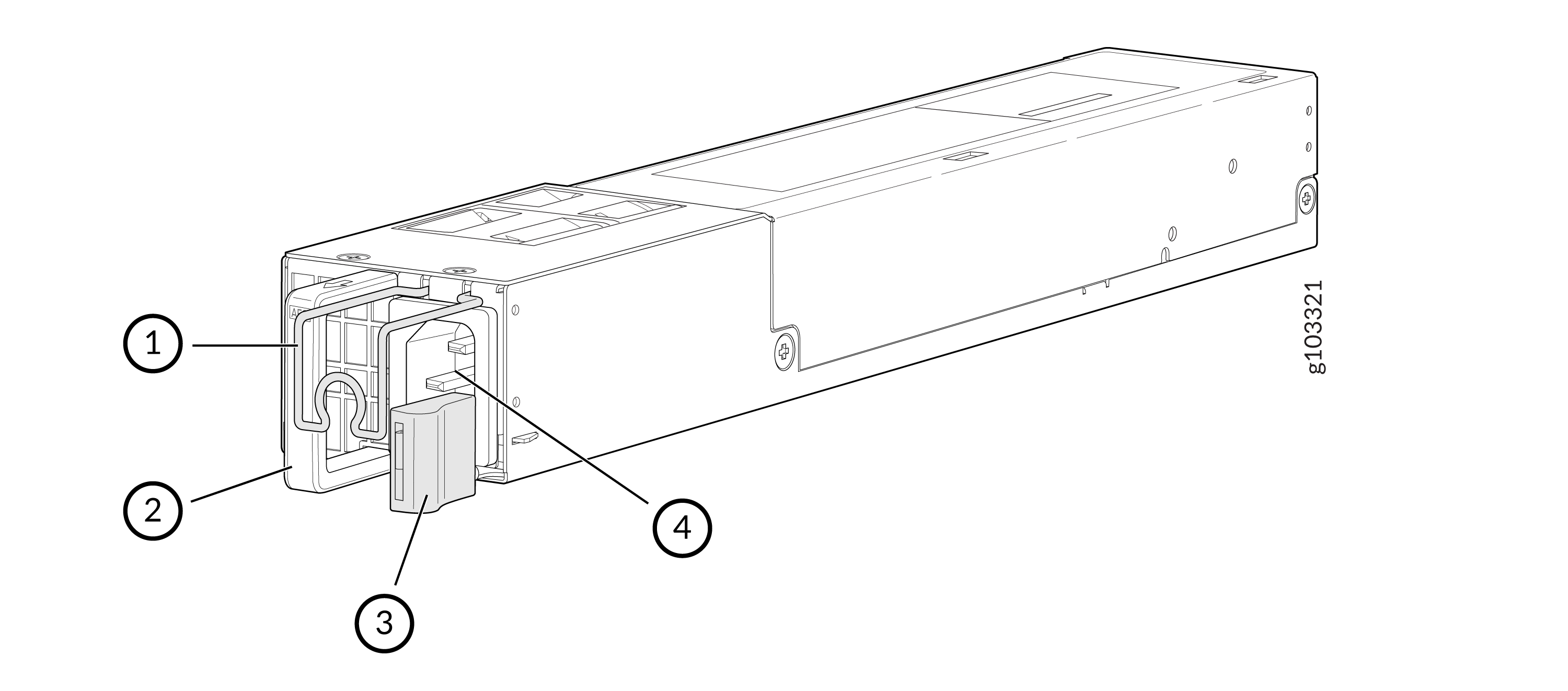
Table 2 describes the components on the JPSU-850W-AC-AFO in isometric view.
| Callout | Name |
|---|---|
|
1 |
Power cord retainer |
|
2 |
Handle |
|
3 |
Release latch |
|
4 |
Power inlet |
JPSU-850W-AC-AFO Specifications
Table 3 lists the physical specifications of the JPSU-850W-AC-AFO PSU. The power specifications are listed in Table 4.
| Specification | Value |
|---|---|
|
Height |
1.73 in. (4.4 cm) |
|
Width |
2.14 in. (5.45 cm) |
|
Depth |
13 in. (33 cm) |
|
Weight |
2.26 lb (1.025 kg) per unit |
|
Airflow |
AFO |
| Specification | Value |
|---|---|
|
Maximum power output |
850 W |
|
AC input voltage |
Operating ranges:
|
|
AC input current rating |
|
|
AC input line frequency |
Typical: 50 Hz through 60 Hz |
|
Circuit breaker rating |
The overcurrent protection for the device is provided by the building installation. Ensure that the branch circuit breaker is rated at no more than 16 A in the EU, 20 A in the USA, or as required by the local code. |
JPSU-850W-AC-AFO LEDs
Each JPSU-850W-AC-AFO has three status LEDs on the PSU faceplate (see Figure 4).
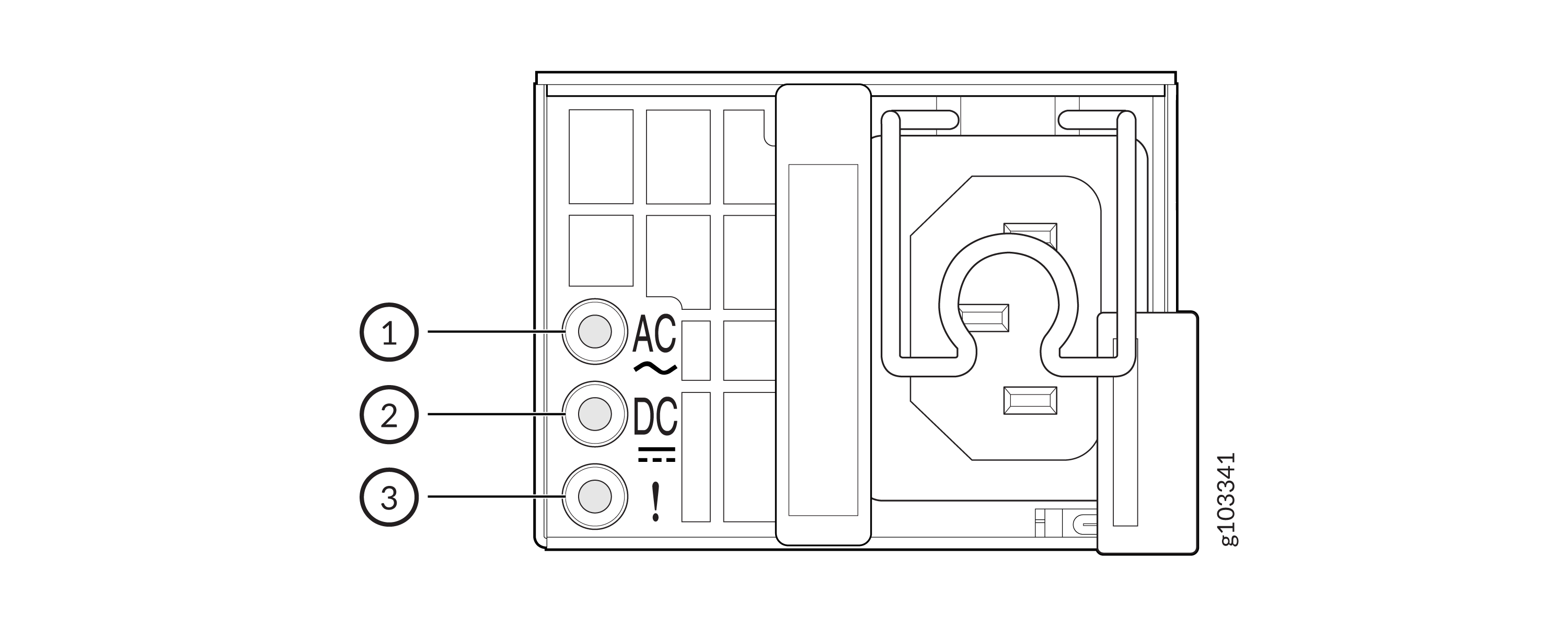
Table 5 describes the JPSU-850W-AC-AFO PSU status LEDs.
| Callout | Label | LED Color | LED State | Description |
|---|---|---|---|---|
| 1 | AC (input) |
Unlit |
Off |
The PSU is disconnected from the power source or the PSU is not receiving power. |
| Green | On Steadily |
The PSU is receiving power. |
||
| 2 | DC (output) |
Unlit |
Off |
The PSU is experiencing overcurrent or power limit. |
|
Green |
On Steadily |
The PSU is sending out power correctly. |
||
| 3 | ! (Fault) |
Amber |
On Steadily |
An error has been detected in the PSU. Replace the PSU as soon as possible. To maintain proper airflow through the chassis, leave the PSU installed in the chassis until you are ready to replace it. |
-
If the AC LED and DC LED are unlit, either the AC power cord is not installed properly or the PSU fuse has failed.
-
If the AC LED is lit green and DC LED is unlit, the AC PSU is installed properly, but the PSU is off in a 5 Voltage Standby (VSB) mode.
-
If the AC LED is lit green, DC LED is unlit, and the ! fault LED is lit amber, the PSU has shut down due to a failure.
You can get additional information about the status of the PSUs using the
show chassis power command and the show chassis power
detail command. Here are some examples of the CLI output:
MX301 with Two AC PSUs
user@device> show chassis power
PEM 0:
  State:     Offline
  Capacity:  850 W (maximum 850 W)
  AC input:  Not ready
  DC output: 0 W (zone 0, 0.00 A at 0.00 V, 0% of capacity)

PEM 1:
  State:     Online
  Capacity:  850 W (maximum 850 W)
  AC input:  OK (INP1 feed expected, INP1 feed connected)
  DC output: 132 W (zone 0, 11.00 A at 12.06 V, 15% of capacity)

System:
  Zone 0:
      Capacity:          850 W (maximum 850 W)
      Allocated power:   820 W (30 W remaining)
      Actual usage:      132 W
  Total system capacity: 850 W (maximum 850 W)
  Total remaining power: 30 W


user@device> show chassis power detail
PEM 0:
  State:     Offline
  Capacity:  850 W (maximum 850 W)
  AC input:  Not ready
  DC output: 0 W (zone 0, 0.00 A at 0.00 V, 0% of capacity)

PEM 1:
  State:     Online
  Capacity:  850 W (maximum 850 W)
  AC input:  OK (INP1 feed expected, INP1 feed connected)
  DC output: 126 W (zone 0, 10.50 A at 12.06 V, 14% of capacity)

System:
  Zone 0:
      Capacity:          850 W (maximum 850 W)
      Allocated power:   820 W (30 W remaining)
      Actual usage:      126 W
  Total system capacity: 850 W (maximum 850 W)
  Total remaining power: 30 W

Item                 Used(W)
  Fan Tray 0              2
  Fan Tray 1              1
  Fan Tray 2              1
  Fan Tray 3              1
  Fan Tray 4              1
  Fan Tray 5              2
  RE0/CB0                53
  FPC 0                  83
Supported AC Power Cords on the JPSU-850W-AC-AFO
A detachable AC power cord is supplied with the AC PSUs. The coupler is type C19 as described by the International Electrotechnical Commission (IEC) standard 60320. Table 6 lists the default power cord that is provided for each country. The plug end of the power cord fits into the power source outlet that is standard for your geographical location.
The AC power cord provided with each PSU is intended for use with that PSU only and not for any other use.
In North America, AC power cords must not exceed 4.5 meters in length to comply with National Electrical Code (NEC) Sections 400-8 (NFPA 75, 5-2.2) and 210-52 and Canadian Electrical Code (CEC) Section 4-010(3). The cords supplied with the router are in compliance with these requirements.
| Country/Geographical Region | Cord Set Rating | Plug Standard | Spare Juniper Model Number |
|---|---|---|---|
|
Argentina |
250 VAC, 10 A, 50 Hz |
IRAM2073 |
CBL-EX-PWR-C13-AR |
|
Australia |
250 VAC, 10 A, 50 Hz |
AS/NZ 3109-1996 |
CBL-EX-PWR-C13-AU |
|
Brazil |
250 VAC, 10 A, 50 Hz |
NBR 14136 Type BR/3 |
CBL-EX-PWR-C13-BR |
|
China |
250 VAC, 10 A, 50 Hz |
GB 1002-1996 |
CBL-EX-PWR-C13-CH |
|
Europe |
250 VAC, 10 A, 50 Hz |
CEE (7) VII |
CBL-EX-PWR-C13-EU |
|
India |
250 VAC, 10 A, 50 Hz |
IS 1293 |
CBL-EX-PWR-C13-IN |
|
Israel |
250 VAC, 10 A, 50 Hz |
SI 32/1971 Type IL/3G |
CBL-EX-PWR-C13-IL |
|
Italy |
250 VAC, 10 A, 50 Hz |
CEI 23-16/VII |
CBL-EX-PWR-C13-IT |
|
Japan |
125 VAC, 12 A, 50 Hz or 60 Hz |
JIS C8303 |
CBL-EX-PWR-C13-JP |
|
North America |
125 VAC, 13 A, 60 Hz 250 VAC, 13 A, 60 Hz 250 VAC, 13 A, 60 Hz |
CAN/CSA No. 49-92 NEMA L6-15 NEMA 6-15 |
CBL-EX-PWR-C13-US |
|
South Africa/India |
250 VAC, 10 A, 50 Hz |
SABS 164/1:1992 Type ZA/3 |
CBL-EX-PWR-C13-SA |
|
South Korea |
250 VAC, 10 A, 60 Hz; 250 VAC, 13 A, 60 Hz |
KSC 8305; K60884-1 |
CBL-EX-PWR-C13-KR |
|
Switzerland |
250 VAC, 10 A, 50 Hz |
SEV 1011 SEV 1991; EN 60320 C13 |
CBL-EX-PWR-C13-SZ |
|
Taiwan |
125 VAC, 11 A and 15 A, 50 Hz |
NEMA 5-15P Type N5-15P |
CBL-EX-PWR-C13-TW |
|
United Kingdom |
250 VAC, 10 A, 50 Hz |
BS 1363/A |
CBL-EX-PWR-C13-UK |
JPSU-850W-DC-AFO
- JPSU-850W-DC-AFO
- JPSU-850W-DC-AFO Specifications
- JPSU-850W-DC-AFO LEDs
- DC Power Cable Specifications
JPSU-850W-DC-AFO
Figure 5 shows the location of the PSUs on the rear panel.
1 — Grounding point | 3 — DC PSU (2 units) |
2 — Fan modules (6 units) |
Figure 6 shows the components on the JPSU-850W-DC-AFO PSU.
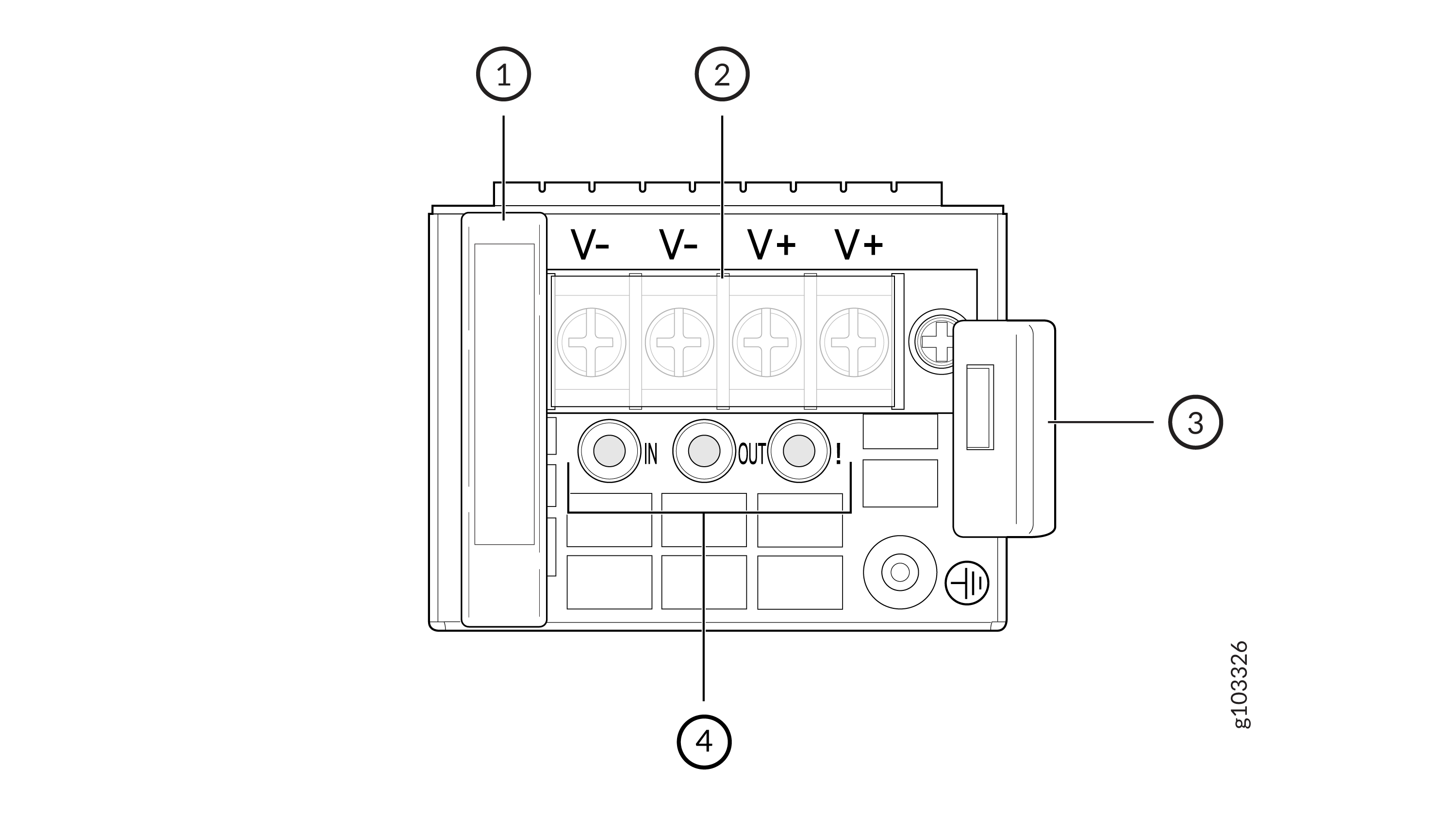
Table 7 describes the components on the JPSU-850W-DC-AFO.
| Callout | Name |
|---|---|
|
1 |
Handle |
|
2 |
Terminal block cover |
|
3 |
Release latch |
|
4 |
Power status LEDs |
Figure 7 shows the components on the JPSU-850W-DC-AFO PSU in isometric view.
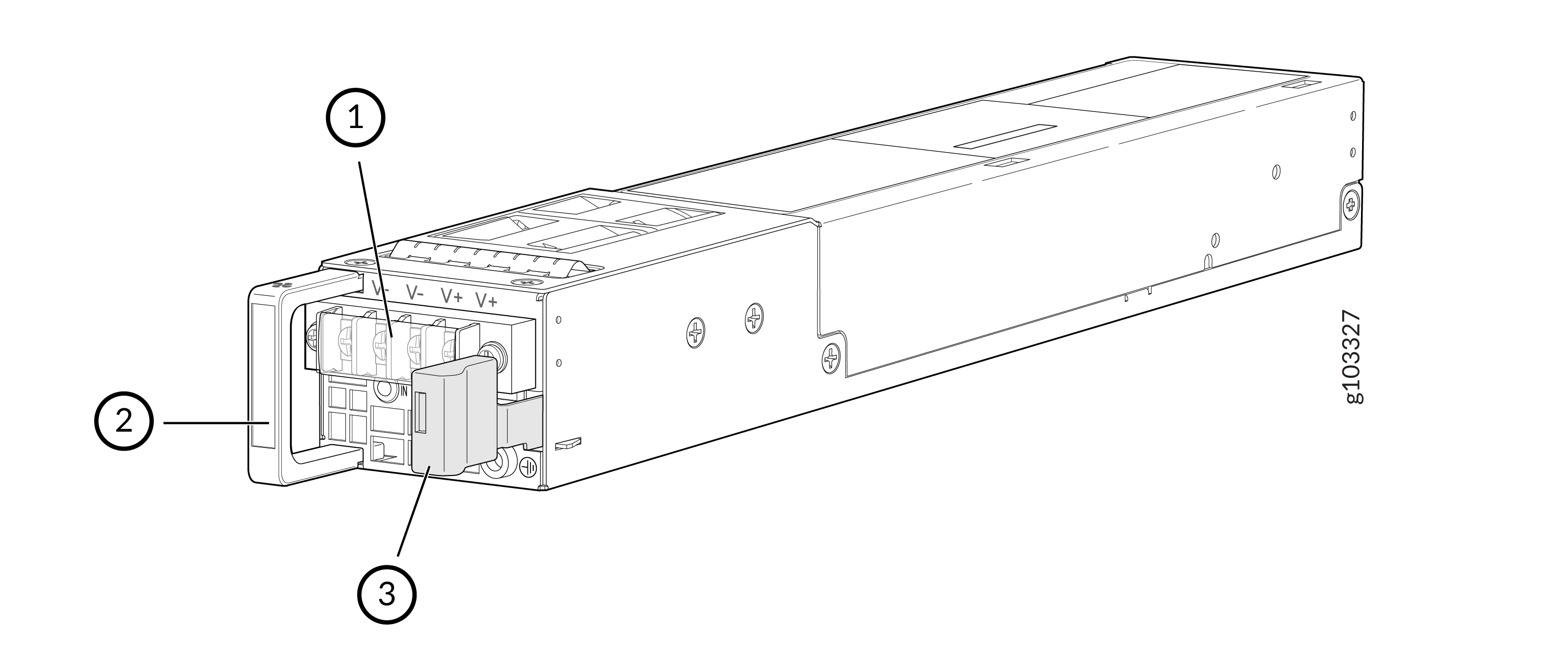
Table 8 describes the components on the JPSU-850W-DC-AFO in isometric view.
| Callout | Name |
|---|---|
|
1 |
Terminal block cover |
|
2 |
Handle |
|
3 |
Release latch |
JPSU-850W-DC-AFO Specifications
Table 9 lists the physical specifications of the JPSU-850W-DC-AFO PSU. The power specifications are listed in Table 10.
| Specification | Value |
|---|---|
|
Height |
1.73 in. (4.4 cm) |
|
Width |
2.14 in. (5.45 cm) |
|
Depth |
13 in. (33 cm) |
|
Weight |
2.16 lb (0.98 kg) per unit |
|
Airflow |
AFO |
| Specification | Value |
|---|---|
|
Maximum power output |
850 W |
|
DC input voltage |
-40 VDC through -72 VDC Typical: -48 VDC |
|
DC input current rating |
21 A through 11 A @ -40 VDC through -72 VDC Typical: 18 A @ -48 VDC |
|
Circuit breaker rating |
30 A |
We recommend that you connect each DC PSU unit to a dedicated DC power source with an output voltage range between -40 VDC through -72 VDC. The wiring from the dedicated DC power source that connects to the DC PSU unit must be within the same building.
JPSU-850W-DC-AFO LEDs
Each JPSU-850W-DC-AFO has three status LEDs on the PSU faceplate (see Figure 8).
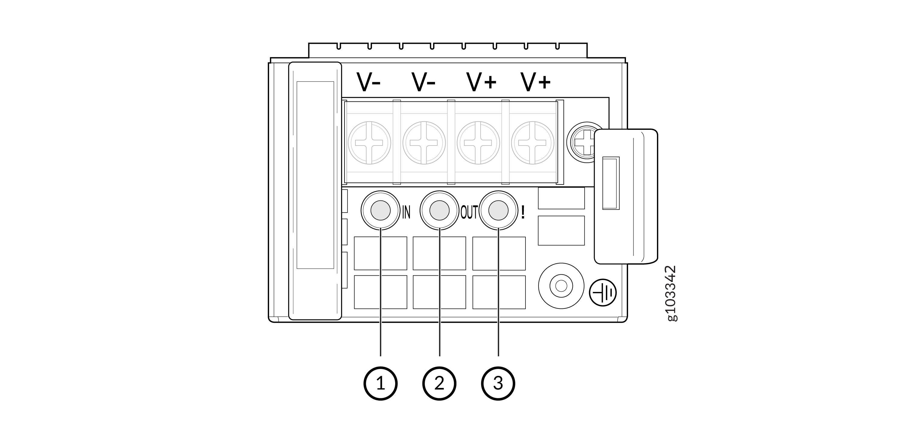
Table 11 describes the JPSU-850W-DC-AFO PSU status LEDs.
| Callout | Label | LED Color | LED State | Description |
|---|---|---|---|---|
| 1 | IN (DC input) |
Unlit |
Off |
The PSU is disconnected from the power source or the PSU is not receiving power. |
| Green | On Steadily |
The PSU is receiving power. |
||
| 2 | OUT (DC output) |
Unlit |
Off |
The PSU is experiencing overcurrent or power limit. |
|
Green |
On Steadily |
The PSU is sending out power correctly. |
||
| 3 | ! (Fault) |
Amber |
On Steadily |
An error has been detected in the PSU. Replace the PSU as soon as possible. To maintain proper airflow through the chassis, leave the PSU installed in the chassis until you are ready to replace it. |
You can get additional information about the status of the PSUs using the
show chassis power command and the show chassis power
detail command. Here are some examples of the CLI output:
MX301 with Two DC PSUs
user@device> show chassis power
PEM 0:
  State:     Online
  Capacity:  850 W (maximum 850 W)
  DC input:  OK (INP1 feed expected, INP1 feed connected)
  DC output: 148 W (zone 0, 12.25 A at 12.14 V, 17% of capacity)

PEM 1:
  State:     Online
  Capacity:  850 W (maximum 850 W)
  DC input:  OK (INP1 feed expected, INP1 feed connected)
  DC output: 159 W (zone 0, 13.13 A at 12.11 V, 18% of capacity)

System:
  Zone 0:
      Capacity:          1700 W (maximum 1700 W)
      Allocated power:   820 W (880 W remaining)
      Actual usage:      307 W
  Total system capacity: 1700 W (maximum 1700 W)
  Total remaining power: 880 W


user@device> show chassis power detail
PEM 0:
  State:     Online
  Capacity:  850 W (maximum 850 W)
  DC input:  OK (INP1 feed expected, INP1 feed connected)
  DC output: 148 W (zone 0, 12.25 A at 12.14 V, 17% of capacity)

PEM 1:
  State:     Online
  Capacity:  850 W (maximum 850 W)
  DC input:  OK (INP1 feed expected, INP1 feed connected)
  DC output: 157 W (zone 0, 13.00 A at 12.09 V, 18% of capacity)

System:
  Zone 0:
      Capacity:          1700 W (maximum 1700 W)
      Allocated power:   820 W (880 W remaining)
      Actual usage:      305 W
  Total system capacity: 1700 W (maximum 1700 W)
  Total remaining power: 880 W

Item                 Used(W)
  Fan Tray 0             15
  Fan Tray 1             16
  Fan Tray 2             16
  Fan Tray 3             15
  Fan Tray 4             15
  Fan Tray 5             16
  RE0/CB0                57
  FPC 0                  67
DC Power Cable Specifications
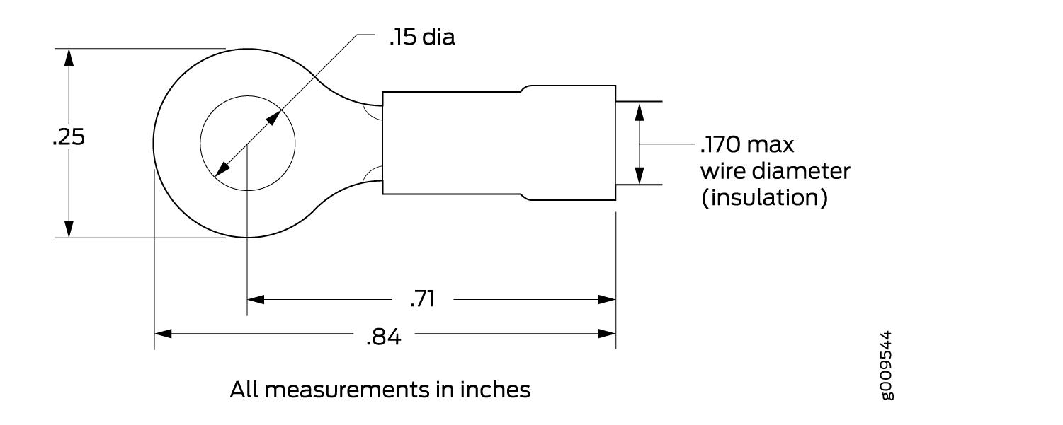
You must supply four DC power cables that meet the following specifications: 14-16 AWG (2.08 - 1.3 mm2), minimum 60° C wire, or as required by the local code. The accessory box shipped with the router includes the cable lugs that attach to the terminal of each PSU.
JPSU-850W-HV-AFO
- JPSU-850W-HV-AFO
- JPSU-850W-HV-AFO Specifications
- JPSU-850W-HV-AFO LEDs
- Supported Power Cords on the JPSU-850W-HV-AFO
JPSU-850W-HV-AFO
Figure 10 shows the location of the PSUs on the back panel.
1 — Grounding point | 3 — HVAC/DC PSU (2 units) |
2 — Fan modules (6 units) |
Figure 11 shows the components on the JPSU-850W-HV-AFO PSU.
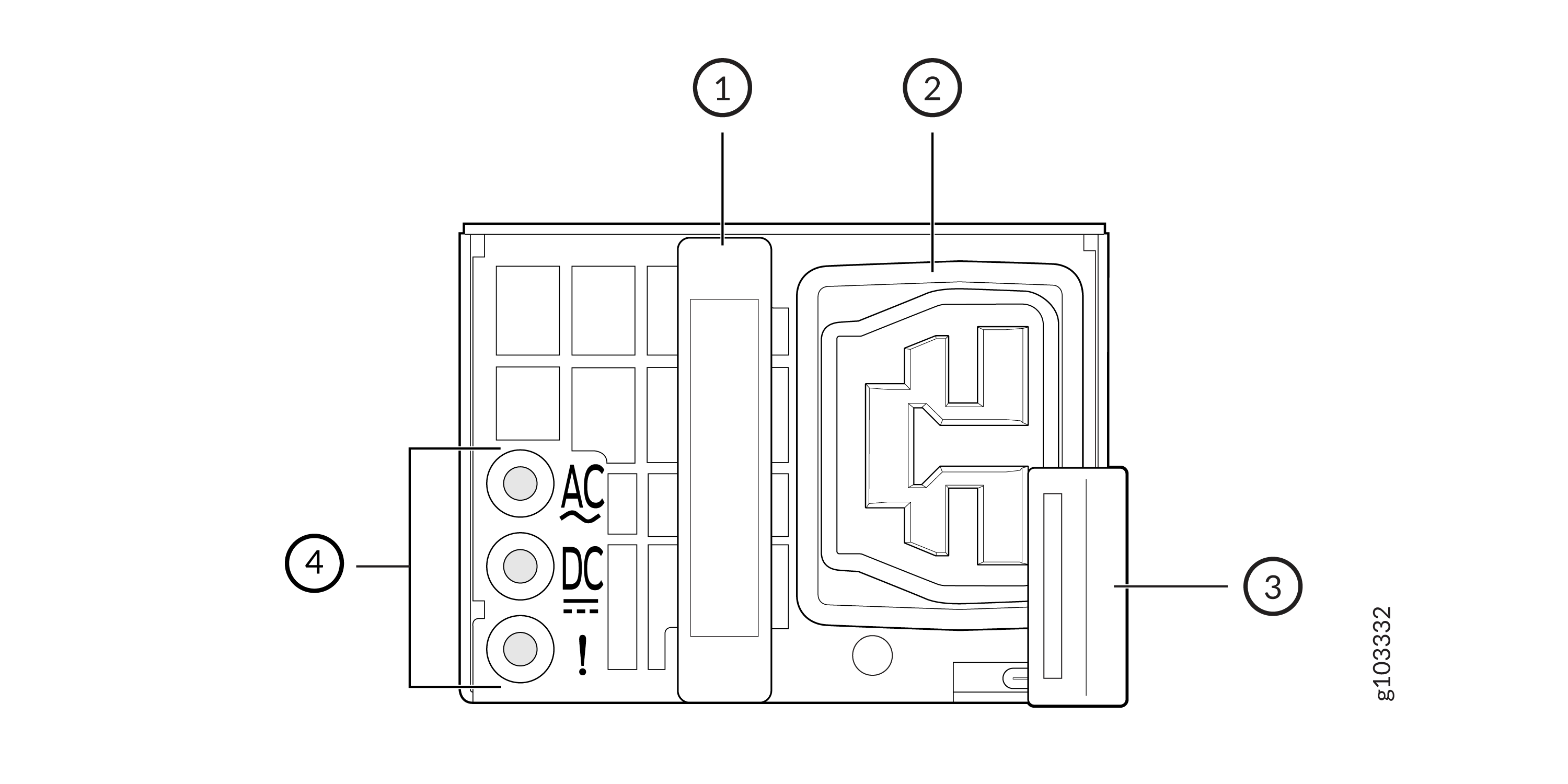
Table 12 shows the components on the JPSU-850W-HV-AFO PSU.
| Callout | Name |
|---|---|
|
1 |
Handle |
|
2 |
Power inlet |
|
3 |
Release latch |
|
4 |
Power status LEDs |
Figure 12 shows the components on the JPSU-850W-HV-AFO PSU in isometric view.

Table 13 shows the components on the JPSU-850W-HV-AFO PSU in isometric view.
| Callout | Name |
|---|---|
|
1 |
Power inlet |
|
2 |
Handle |
|
3 |
Release latch |
JPSU-850W-HV-AFO Specifications
Table 14 lists the physical specifications of the JPSU-850W-HV-AFO PSU. The power specifications are listed in Table 15.
| Specification | Value |
|---|---|
|
Height |
1.73 in. (4.4 cm) |
|
Width |
2.14 in. (5.45 cm) |
|
Depth |
13 in. (33 cm) |
|
Weight |
2.21 lb (1.005 kg) per unit |
|
Airflow |
AFO |
| Specification | Value |
|---|---|
|
Maximum power output |
850 W |
|
Input voltage |
HVAC
HVDC
|
|
Input current rating |
AC
DC
|
|
Input line frequency for AC input |
50 Hz through 60 Hz |
|
Circuit breaker rating |
HVAC
HVDC
|
JPSU-850W-HV-AFO LEDs
Each JPSU-850W-HV-AFO has three status LEDs on the PSU faceplate (see Figure 13).
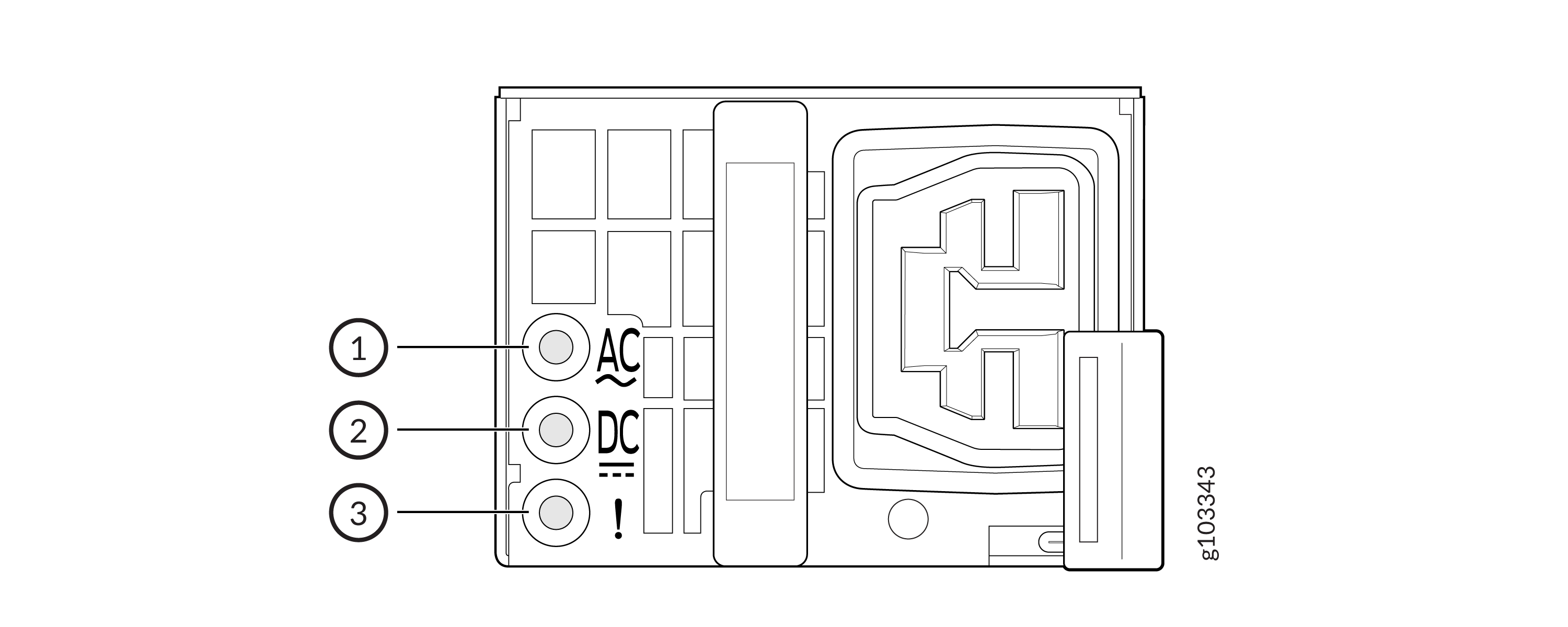
Table 16 describes the JPSU-850W-AC-AFO PSU status LEDs.
| Callout | Label | LED Color | LED State | Description |
|---|---|---|---|---|
| 1 | AC (input) |
Unlit |
Off |
The PSU is disconnected from power source or the PSU is not receiving power. |
| Green | On Steadily |
The PSU is receiving power. |
||
| 2 | DC (output) |
Unlit |
Off |
The PSU is experiencing overcurrent or power limit. |
|
Green |
On Steadily |
The PSU is sending out power correctly. |
||
| 3 | ! (Fault) |
Amber |
On Steadily |
An error has been detected in the PSU. Replace the PSU as soon as possible. To maintain proper airflow through the chassis, leave the PSU installed in the chassis until you are ready to replace it. |
You can get additional information about the status of the PSUs using the
show chassis power command and the show chassis power
detail command. Here are some examples of the CLI output:
MX301 with Two HVAC/DC PSUs
user@device> show chassis power
PEM 0:
  State:     Online
  Capacity:  850 W (maximum 850 W)
  AC input:  OK (INP1 feed expected, INP1 feed connected)
  DC output: 133 W (zone 0, 10.75 A at 12.38 V, 15% of capacity)

PEM 1:
  State:     Online
  Capacity:  850 W (maximum 850 W)
  AC input:  OK (INP1 feed expected, INP1 feed connected)
  DC output: 126 W (zone 0, 10.25 A at 12.39 V, 14% of capacity)

System:
  Zone 0:
      Capacity:          1700 W (maximum 1700 W)
      Allocated power:   820 W (880 W remaining)
      Actual usage:      259 W
  Total system capacity: 1700 W (maximum 1700 W)
  Total remaining power: 880 W


user@device> show chassis power detail
PEM 0:
  State:     Online
  Capacity:  850 W (maximum 850 W)
  AC input:  OK (INP1 feed expected, INP1 feed connected)
  DC output: 133 W (zone 0, 10.75 A at 12.38 V, 15% of capacity)

PEM 1:
  State:     Online
  Capacity:  850 W (maximum 850 W)
  AC input:  OK (INP1 feed expected, INP1 feed connected)
  DC output: 126 W (zone 0, 10.25 A at 12.39 V, 14% of capacity)

System:
  Zone 0:
      Capacity:          1700 W (maximum 1700 W)
      Allocated power:   820 W (880 W remaining)
      Actual usage:      259 W
  Total system capacity: 1700 W (maximum 1700 W)
  Total remaining power: 880 W

Item                 Used(W)
  Fan Tray 0             16
  Fan Tray 1             17
  Fan Tray 2             17
  Fan Tray 3             16
  Fan Tray 4             16
  Fan Tray 5             18
  RE0/CB0                58
  FPC 0                  21
Supported Power Cords on the JPSU-850W-HV-AFO
Table 17 lists the specifications of the power cord for the high-voltage PSUs provided for countries and regions.
The power cord provided with each PSU is intended for use with that PSU only and not for any other use.
In North America, AC power cords must not exceed 4.5 meters in length, to comply with National Electrical Code (NEC) Sections 400-8 (NFPA 75, 5-2.2) and 210-52 and Canadian Electrical Code (CEC) Section 4-010(3). The cords supplied with the router are in compliance.
| Country/Geographical Region | Cord Set Rating | Plug Standard | Spare Juniper Model Number | Graphic |
|---|---|---|---|---|
|
Argentina |
16 A, 250 VAC |
IRAM 2073 Type RA/3 |
CBL-JNP-SG4-AR |
|
|
Australia and New Zealand |
15 A, 250 VAC |
AS/NZS 4417 |
CBL-JNP-SG4-AU |
|
|
Brazil |
16 A, 250 VAC |
NBR 14136 Type BR/3 |
CBL-JNP-SG4-BR |
|
|
China |
16 A, 250 VAC |
GB2099 |
CBL-JNP-SG4-CH |
|
|
Great Britain |
13 A, 250 VAC |
BS1363 |
CBL-JNP-SG4-UK |
|
|
India |
16 A, 250 VAC |
SANS 164-1 |
CBL-JNP-SG4-SA |
|
|
Israel |
16 A, RA, 250 VAC |
SI 32/1971 Type IL/3G |
CBL-JNP-SG4-IL |
|
|
Italy |
16 A, 250 VAC |
CEI 23-16 |
CBL-JNP-SG4-IT |
|
|
North America |
16 A, 250 VAC |
Locking NEMA L6-20P |
CBL-JNP-SG4-US-L |
|
|
16 A, 250 VAC |
NEMA 6-20P |
CBL-JNP-SG4-US |
|
|
|
15 A, 277 V |
NEMA I7-20P |
CBL-JNP-SG4-HVAC |
|
|
|
South Africa |
16 A, 250 VAC |
SANS 164-1 |
CBL-JNP-SG4-SA |
|
|
Switzerland |
16 A, 250 VAC |
CEI 23-50 |
CBL-JNP-SG4-SZ |
|
|
All countries |
16 A, 400 VAC |
Anderson/straight to bare wire |
CBL-PWR2-BARE |
See Figure 14. |
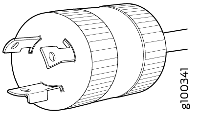
The JPSU-850W-HV-AFO PSU uses an Anderson SAF-D power connector for its HVAC/DC PSU power inlet. The cable has an Anderson connector on one end and bare wire on the other. This bare wire can be used to connect to DC power outlet and is shipped without any lug attached.
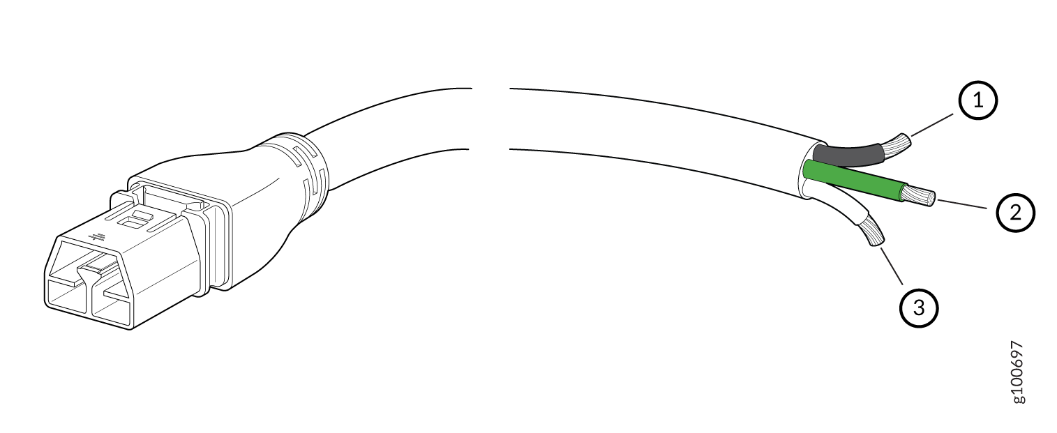
1 — Black wire–Return (+) | 3 — White wire–Neutral |
2 — Green wire-Ground |