MX301 Chassis LEDs
This topic describes the status LEDs for the chassis and ports on the MX301.
The LEDs on the MX301 indicate the status of the device and its components. You can also use the LEDs for troubleshooting.
Chassis Status LEDs
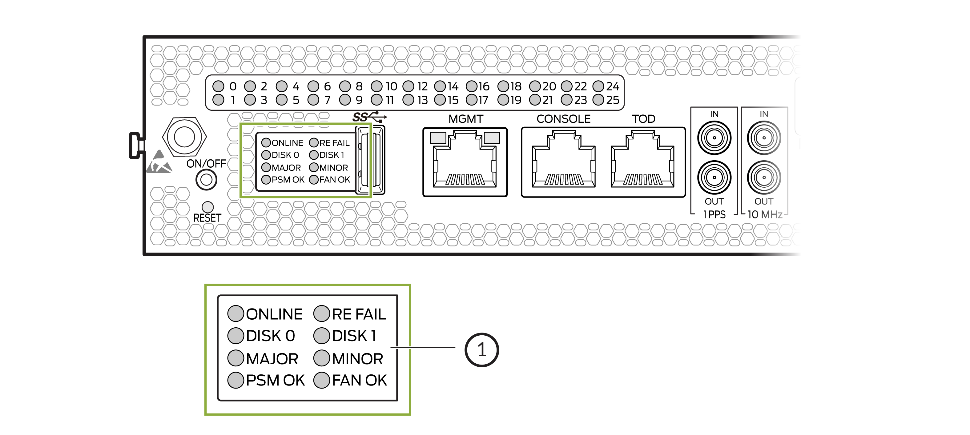
1 — Chassis status LEDs |
| Label | LED Color | LED State | Description |
|---|---|---|---|
|
ONLINE |
Green |
On steadily |
Device is online and working as intended. |
|
Blinking |
Device is booting. |
||
|
Unlit |
Device is offline. |
||
|
RE FAIL |
Green |
On steadily |
Device is operating normally. |
|
Red |
Blinking |
Indicates a fault condition in the device. |
|
|
Unlit |
Device is offline. |
||
|
DISK 0 |
Green |
Blinking |
SSD0 is being accessed by the device. |
|
Unlit |
SSD0 is not active or not being accessed. |
||
|
DISK 1 |
Green |
Blinking |
SSD1 is being accessed by the device. |
|
Unit |
SSD1 is not active or not being accessed. |
||
|
MAJOR |
Red |
On steadily |
Indicates a critical condition that can cause the device to stop functioning. Possible causes include component failure, or a major software failure. |
|
Unlit |
No major alarms are present. |
||
|
MINOR |
Amber |
On steadily |
Indicates a serious but non-fatal error condition such as a maintenance alert or increase in component temperature. |
|
Unlit |
No minor alarms are present. |
||
|
PSM OK |
Green |
On steadily |
Both power supply modules are operating normally. |
|
Yellow |
On steadily |
Indicates an error condition in one or both power supply modules. |
|
|
FAN OK |
Green |
On steadily |
All fan modules are operating normally. |
|
Yellow |
On steadily |
Indicates an error condition in one or all fan modules. |
Management Port Status LEDs
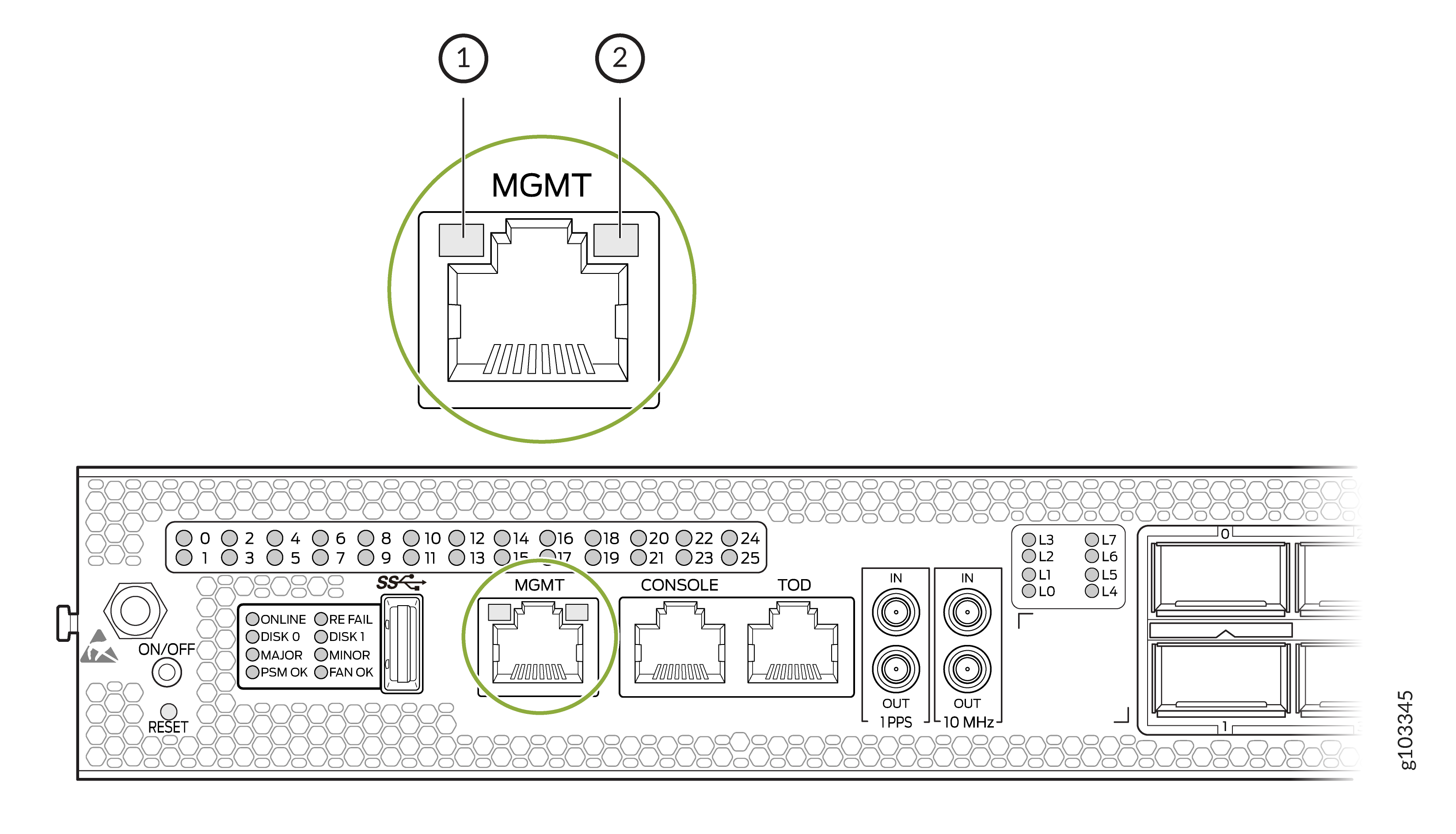
| Callout | Label | LED Color | LED State | Description |
|---|---|---|---|---|
|
1 |
Status |
Green |
On steadily |
The port speed is 1000 Mbps (1 Gbps). |
|
Yellow |
On steadily |
The port speed is 10 Mbps or 100 Mbps. |
||
|
Unlit |
The link is down. |
|||
|
2 |
Link Activity |
Green |
Blinking |
A link is established and there is link activity. |
WAN Port Status LEDs
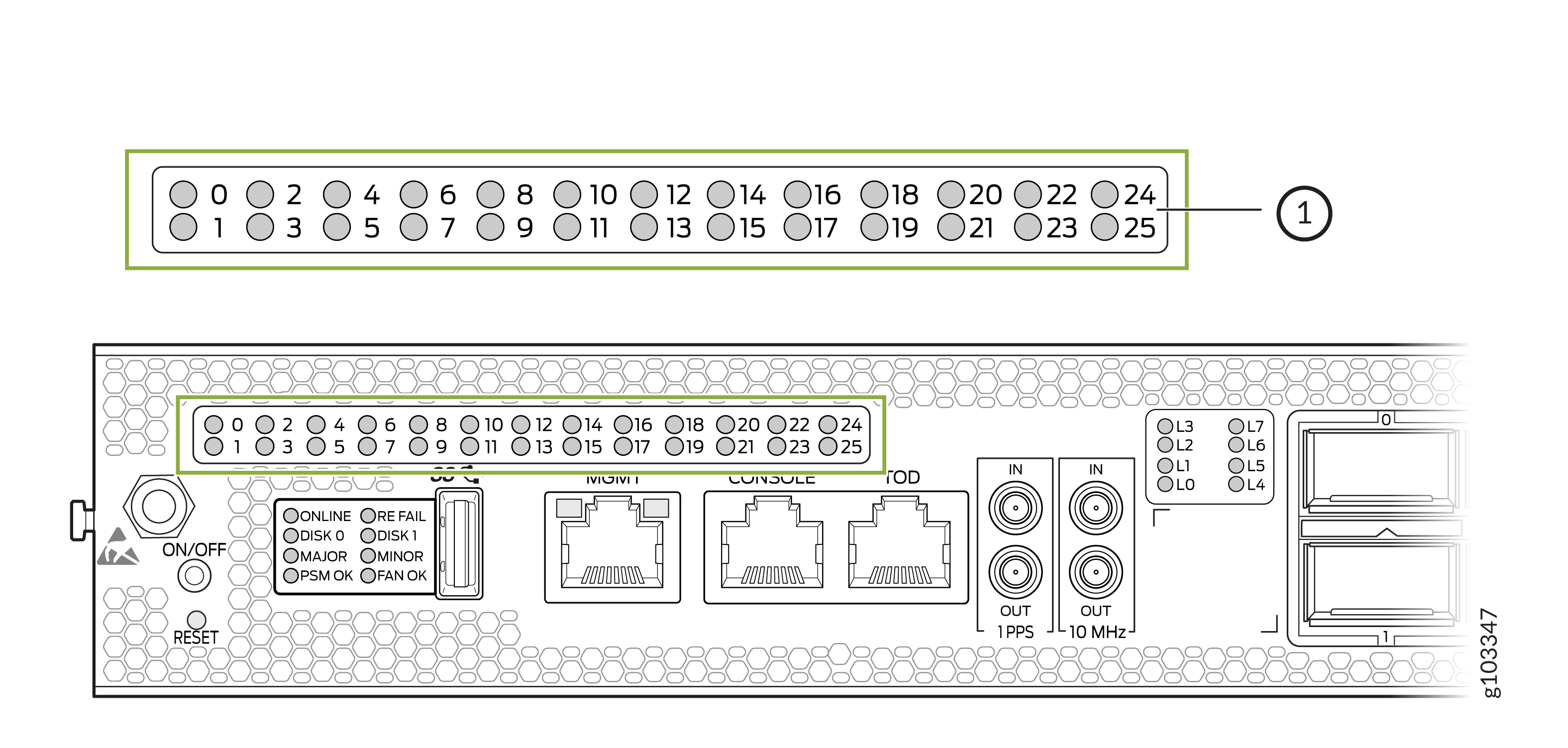
1 — WAN port status LEDs |
The WAN port status LEDS on the MX301 (labeled 0 through 25 for each of the available WAN port) can operate in different display modes:
-
Normal—The port status LED represents the port state or a breakout port state. This is the default mode.
-
Lane Display—When lane display is on, the router cycles through the ports for the lane status display. Only one port is selected and the display mode for that port changes to lane display while the other ports remain in normal display mode. The corresponding array of lane status LEDs displays the status of each individual lane for the selected port (see Table 4).
Note:Ports with all individual links in Up state are skipped and are not considered for lane status display, thereby reducing the time needed to cycle through all the ports.
-
Port Location—The port location (beacon) command (
require chassis port-led
              <start|stop> fpc-slot slot pic-slot slot
              port port [duration time]
) is initiated for a port or a group of ports for a certain period of time. The default duration is five minutes if thedurationkeyword is not specified.Note:The port location command will temporarily override the port LEDs selected for lane display. All other ports will remain in normal display mode.
See Table 3 for the port LED color and blinking state depending on the port configuration, port state, port configuration mode, inserted transceivers, and port display modes.
| Transceiver Inserted? | Breakout Cable Configuration State | Explicitly Disabled? | Port State | Color - Normal | Color - Port Location On | Color - Lane Display (if available) |
|---|---|---|---|---|---|---|
|
Any |
No breakout |
No |
Up |
Green |
Blinking green |
– |
|
Yes |
No breakout |
No |
Down because of transceiver hardware failure |
Red |
Blinking red |
– |
|
Yes |
No breakout |
No |
Down because of a loss of signal (LOS) or Down because of loss of signal (LOS) detection |
Off |
Blinking green |
– |
|
Any |
No breakout |
No |
Down because of any fault except LOS and transceiver hardware failure |
Amber |
Blinking amber |
– |
|
Any |
No breakout |
Yes |
Port disabled in the CLI |
Amber |
Blinking amber |
– |
|
No |
Any |
No |
Anything except disabled port, but no transciever is present |
Off |
Blinking green |
– |
|
Any |
Breakout |
No |
All breakout ports are up |
Green |
Blinking green |
Blinking green |
|
Yes |
Breakout |
No |
Hardware failure because of transceiver initialization error at the port level |
Red |
Blinking red |
Blinking red |
|
Yes |
Breakout |
No |
All breakout ports down with an LOS |
Off |
Blinking green |
Blinking green |
|
Any |
Breakout |
Any |
Any state other than the states described in this table. |
Amber |
Blinking amber |
Blinking amber |
Lane Status LEDs
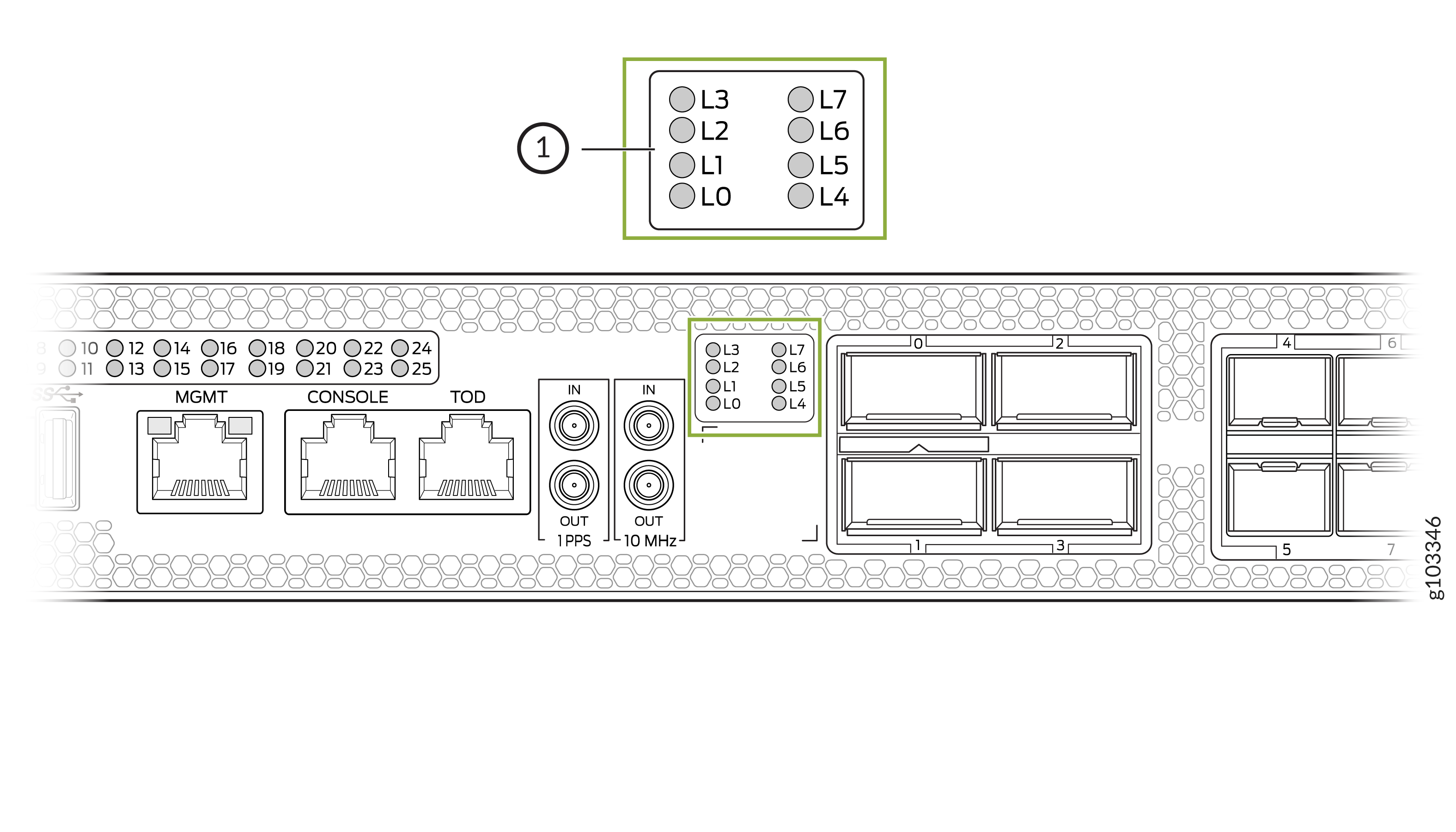
1 — Lane status LEDs |
The MX301 provides eight separate LEDs (labeled L0 through L7) to display the status of ports operating in breakout mode.
The lane status LEDs can be activated for a port if:
-
The port is configured in breakout mode.
-
Transceiver is plugged in.
-
Port location is activated for one port only.
Table 4 describes the lane status LED.
| Transceiver Inserted? | Breakout Cable Configuration State | Explicitly Disabled? | Port State | Color |
|---|---|---|---|---|
|
Yes |
Breakout |
No |
Up |
Green |
|
Yes |
Breakout |
No |
Down because of loss of signal (LOS) detection |
Off |
|
Yes |
Breakout |
No |
Down because of transceiver hardware failure |
Red |
|
Yes |
Breakout |
No |
Down because of any fault except LOS and transceiver hardware failure |
Amber |
|
Yes |
Breakout |
Yes |
The breakout port is disabled in the CLI. |
Amber |