MX301 Chassis
Learn about the components in the MX301 chassis.
The MX301 chassis is a rigid sheet-metal structure that houses all components of the device.
MX301 Specifications
| Specification | Value |
|---|---|
|
Height |
1.75 in. (4.45 cm) |
|
Width |
17.28 in. (44 cm) |
|
Depth |
17.71 in. (45 cm) |
|
Weight |
As shipped: 34.81 lb (15.79 kg) Fully-loaded:
|
| Specification | Value |
|---|---|
|
Operating altitude |
0 ft to 6000 ft (0 m to 1829 m) |
|
Operating temperature |
With 100G optics and below:
With 400G optics:
|
|
Storage temperature |
-40 °C to 70 °C (-40 °F to 158 °F) |
|
Relative humidity (operating) (noncondensing) |
5% to 90% |
|
Relative humidity (nonoperating) (noncondensing) |
5% to 90% |
|
Seismic tolerance |
Designed to meet Telcordia Technologies Zone 4 earthquake requirements. |
|
Average Thermal Output |
300 W x 3.412 = 1024 BTU/hour |
|
Acoustic noise level |
Typical: 58 through 67 dBA |
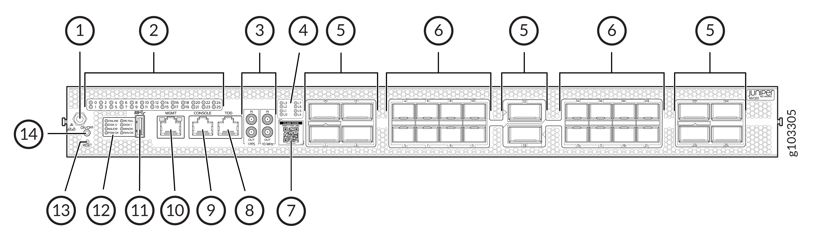
MX301 Front Panel
| Callout | Item | Description |
|---|---|---|
|
1 |
ESD point |
Electrostatic discharge (ESD) point. |
|
2 |
WAN port LEDs |
26 LEDs (labeled 0–25) to indicate the status of each of the 26 network ports. |
|
3 |
1PPS and 10 MHz GPS input and output ports |
1-PPS and 10-MHz input and output external clocking ports with DIN connectors. |
|
4 |
Lane LEDs |
Eight LEDs (labeled L0–L7) to indicate the lane position. |
|
5 |
QSFP ports |
10 QSFP form factor ports where:
|
|
6 |
SFP ports |
16 SFP form factor ports support up to 50GbE speeds. |
|
7 |
Claim code |
Use the QR code to claim, onboard, and monitor your device to Juniper® Routing Director and Juniper® Routing Assurance. |
|
8 |
Time of day (TOD) port |
Ensures precise time synchronization by connecting to external timing sources. |
|
9 |
CONSOLE port |
Enables you to connect a laptop directly to the MX301 console port and manage the device using the CLI. The port uses an RJ-45 serial connection. |
|
10 |
Management port (MGMT) |
Enables you to connect the MX301 to a management network and perform out-of-band management remotely. The management port uses an autosensing RJ-45 Ethernet connector (supports 10-Mbps, 100-Mbps, and 1000-Mbps port speeds). |
|
11 |
USB port |
A USB 3.0 Type A port for plugging in USB storage devices to install Junos OS manually. |
|
12 |
Chassis LEDs |
Eight LEDs to indicate component status, system status, and troubleshooting information at a glance. |
|
13 |
RESET push button |
To reset the device, briefly press the RESET push button. To enter BIOS reset mode, press and hold the RESET push button for approximately 10 seconds. |
|
14 |
ON/OFF push button |
To take the device offline, press the ON/OFF push button for approximately 4 seconds. To bring the device online, press the ON/OFF push button momentarily. |
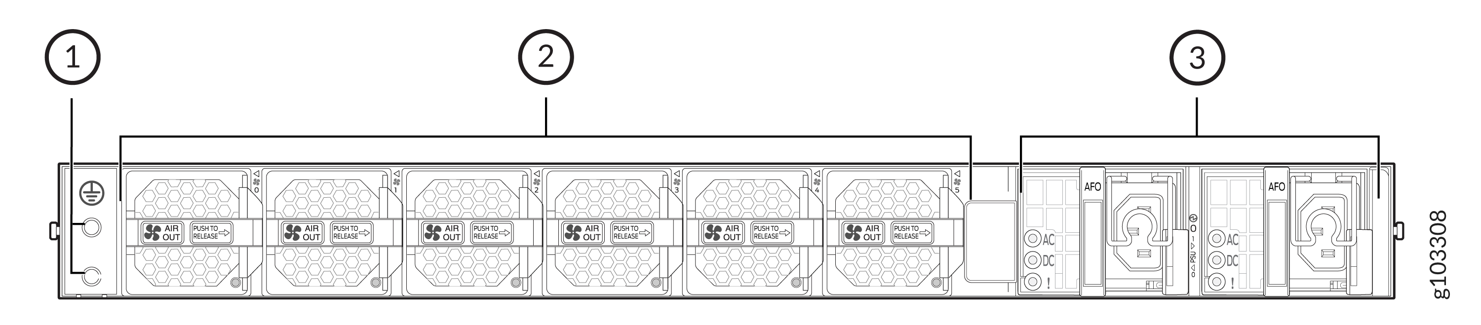
MX301 Rear Panel
| Callout | Item | Description |
|---|---|---|
|
1 |
Grounding point |
Enables you to connect a grounding cable to earth ground and attach it to the MX301 grounding point to ground the device. |
|
2 |
Fan modules |
Six airflow out (AFO) fan modules (5+1 redundancy) |
|
3 |
AC PSU |
Two 850-W AC PSUs (1+1 redundancy) |
| Callout | Item | Description |
|---|---|---|
|
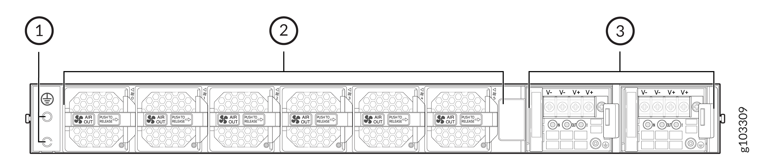
1 |
Grounding point |
Enables you to connect a grounding cable to earth ground and attach it to the MX301 grounding point to ground the device. |
|
2 |
Fan modules |
Six airflow out (AFO) fan modules (5+1 redundancy) |
|
3 |
DC PSUs |
Two 850-W DC PSUs (1+1 redundancy) |
| Callout | Item | Description |
|---|---|---|
|
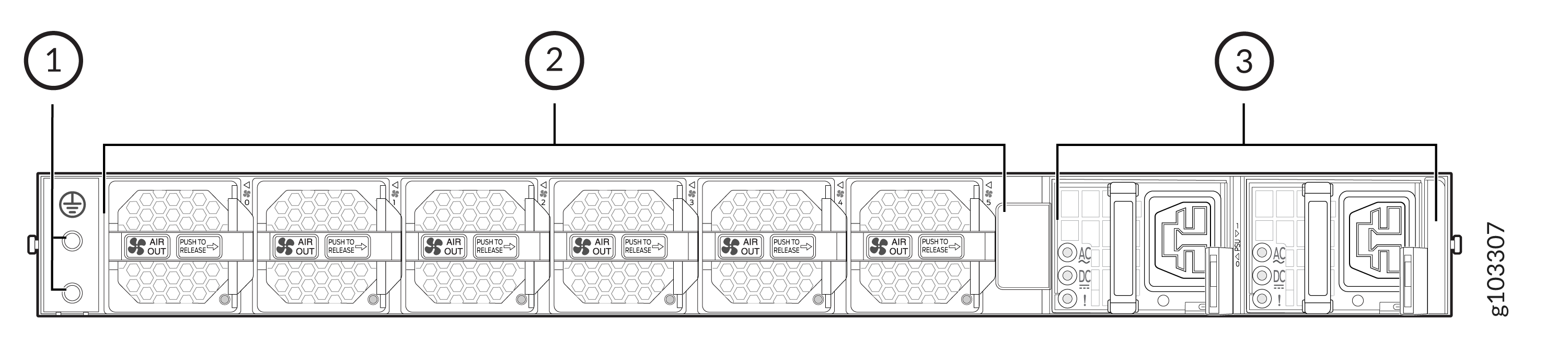
1 |
Grounding point |
Enables you to connect a grounding cable to earth ground and attach it to the MX301 grounding point to ground the device. |
|
2 |
Fan modules |
Six airflow out (AFO) fan modules (5+1 redundancy) |
|
3 |
HVAC/DC PSUs |
Two 850-W high voltage AC/DC PSUs (1+1 redundancy) |