Replacing the MX2010 Craft Interface
Disconnecting the Alarm Relay Wires from the MX2010 Craft Interface
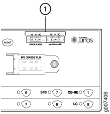
Here’s how to disconnect the alarm relay wires from the MX2010 and an alarm-reporting device (see Figure 1):
- Disconnect the existing wire at the external device.
- Attach an electrostatic discharge (ESD) grounding strap to your bare wrist, and connect the strap to one of the ESD points on the chassis.
- Using a 2.5-mm flat-blade screwdriver, loosen the small screws on the face of the terminal block and remove the block from the relay contact.
- Using the 2.5-mm flat-blade screwdriver, loosen the small screws on the side of the terminal block. Remove existing wires from the slots in the front of the block (see Table 1).
Function No. |
Label |
Description |
|---|---|---|
1 |
MINOR ALARM—[NC C NO] MAJOR ALARM—[NC C NO] |
The alarm relays consist of three terminal contacts with a normal closed (NC), common (C), and normal open (NO) relays that signal a minor or major alarm when broken. |
Removing the MX2010 Craft Interface
Here’s how to remove the MX2010 craft interface:
-
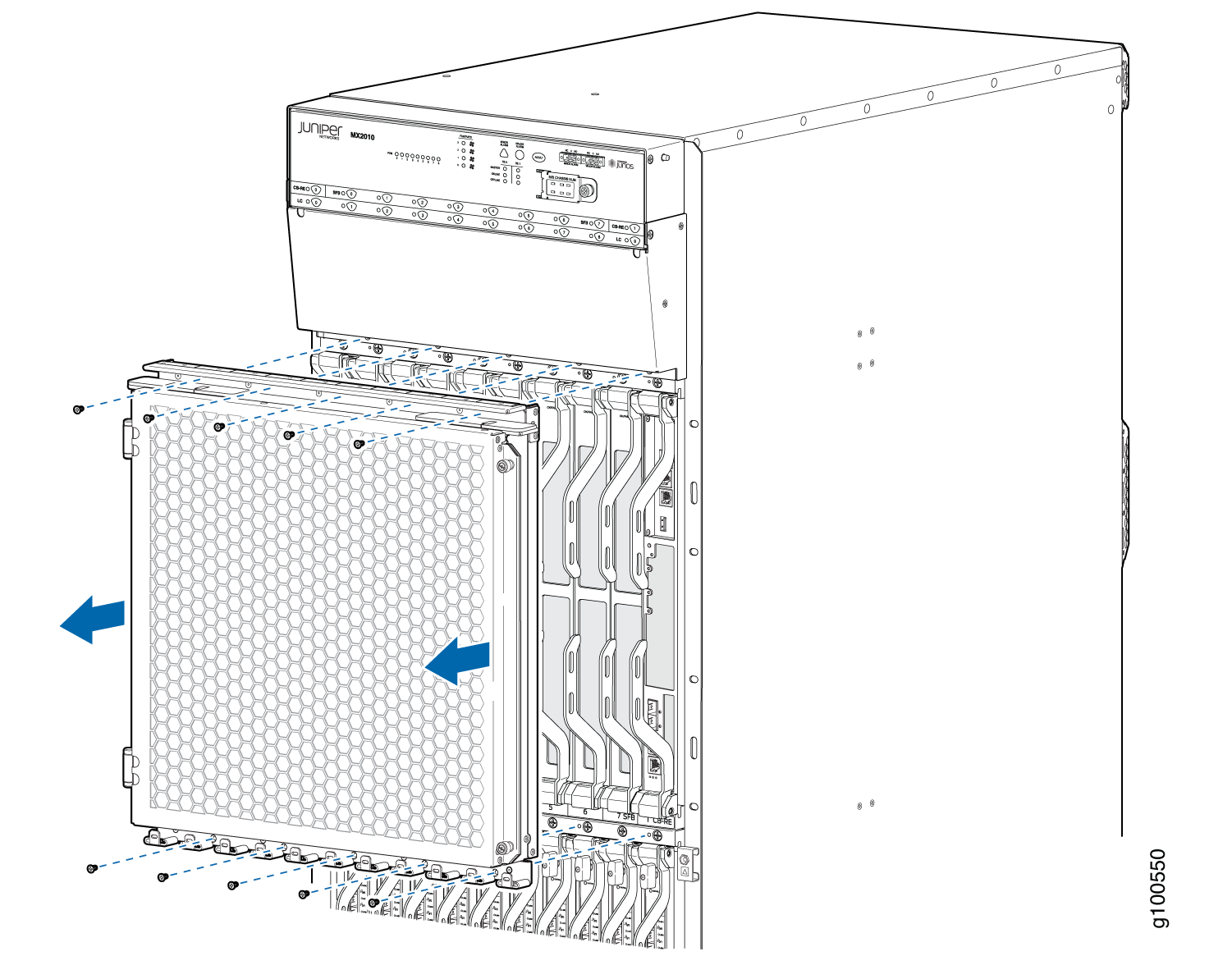
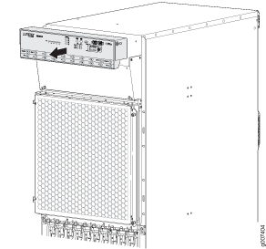
Remove the 10 screws holding the EMI door in place and
remove the EMI door. Refer to Figure 2.
Figure 2: Removing the EMI Door
-
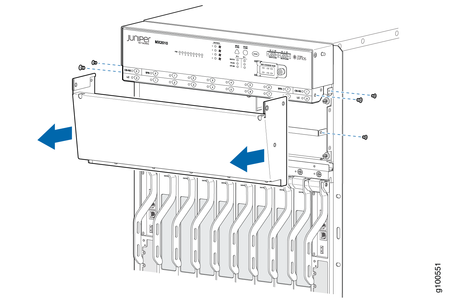
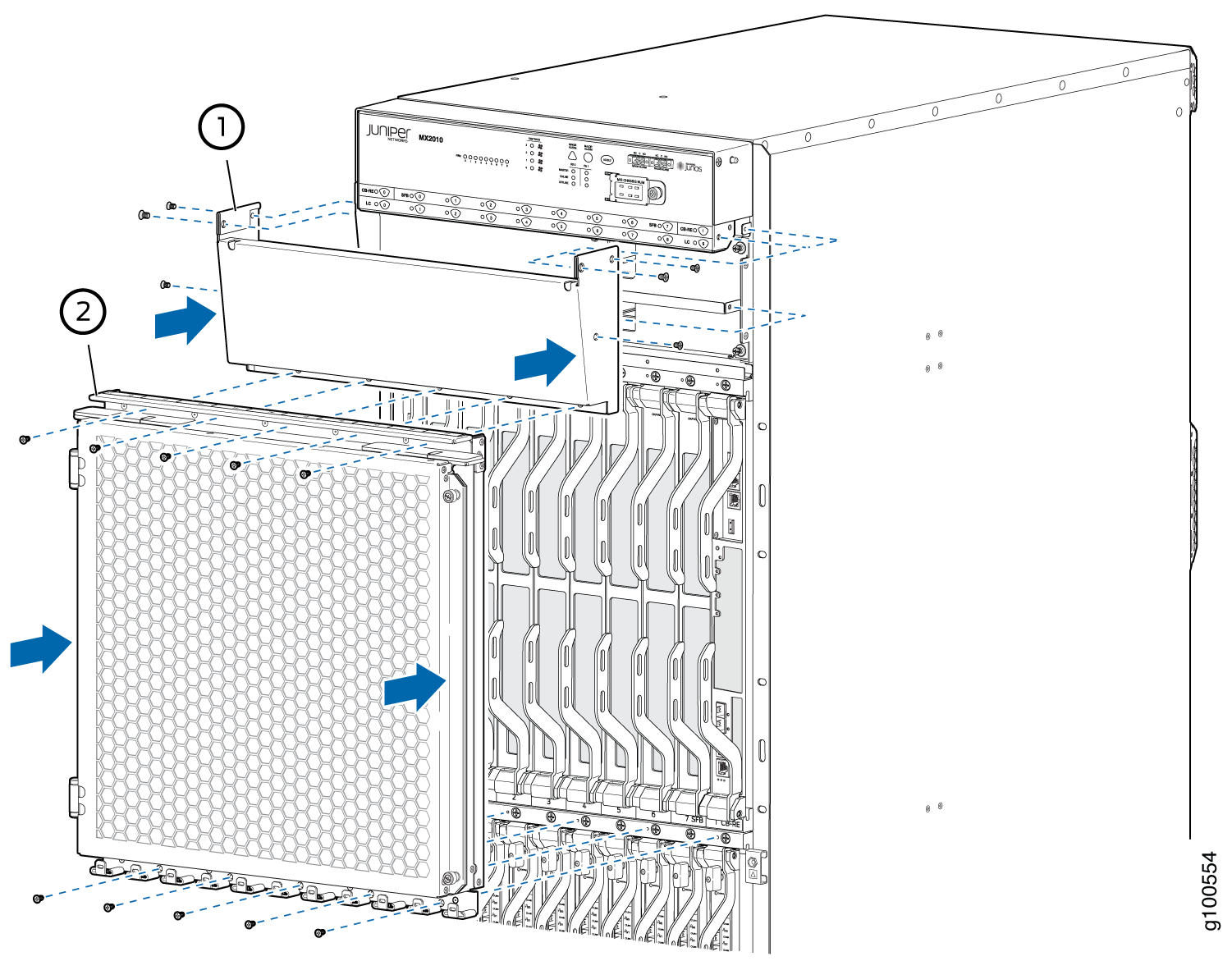
Remove the four screws holding the sheet metal cover in
place and remove the sheet metal cover. Refer to Figure 3.
Figure 3: Removing the Sheet Metal Cover
-
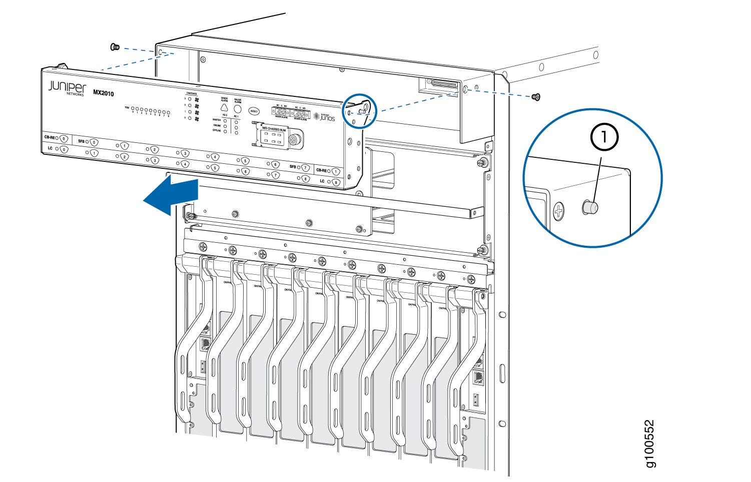
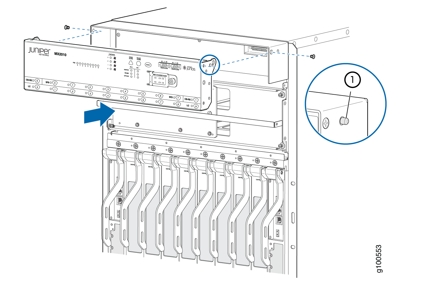
Gently slide the left end of the craft interface out of
the housing. The pin at the right end of the craft interface will
auto-slide out of the dedicated hole. Refer to Figure 4.
Figure 4: Sliding the Craft Interface Out of the Housing
See Also
Installing the MX2010 Craft Interface
Here’s how to install the MX2010 craft interface:
- Align the pin on the right side of the craft interface
with the dedicated hole in the housing and gently slide the craft
interface into the housing. See Figure 6.Figure 6: Installing the Craft Interface into the Housing
- Reattach the sheet metal cover and EMI door by positioning
them in place and then tightening the screws using a Torx (T10) screwdriver.
See Figure 7.Figure 7: Reattaching the Sheet Metal Cover and EMI Door
See Also
Connecting the Alarm Relay Wires to the MX2010 Craft Interface
Here’s how to connect the alarm relay wires between a router and an alarm-reporting device (see Figure 8):
- Prepare the required length of replacement wire with gauge between 28 AWG (0.08 mm2) and 14 AWG (2.08 mm2).
- Insert the replacement wires into the slots in the front of the block (see Table 2). Use a 2.5-mm flat-blade screwdriver to tighten the screws and secure the wire.
- Attach an electrostatic discharge (ESD) grounding strap to your bare wrist, and connect the strap to one of the ESD points on the chassis.
- Plug the terminal block into the relay contact, and use a 2.5-mm flat-blade screwdriver to tighten the screws on the face of the block.
- Attach the other end of the wires to the external device.
Function No. |
Label |
Description |
|---|---|---|
1 |
MINOR ALARM—[NC C NO] MAJOR ALARM—[NC C NO] |
The alarm relays consist of three terminal contacts with a normal closed (NC), a common (C), and a normal open (NO) relay that signal a minor or major alarm when broken. |