Help us improve your experience.

Let us know what you think.

Do you have time for a two-minute survey?


Connecting an MX2000 DC Router Power Distribution Module (240 V China) Cable

Warning:

Before performing DC power procedures, disconnect all power sources. To ensure that all power is OFF, locate the circuit breaker on the panel board that services the DC circuit, switch the circuit breaker to the OFF position, and tape the switch handle of the circuit breaker in the OFF position.

Note:

Ensure that you have connected the chassis to earth ground. See Grounding an MX2000 Router.

To connect the DC (240 V China) source power cables (CBL-PWR-240V-CH) to the router:

  1. Switch off the dedicated customer site circuit breakers. Ensure that the voltage across the DC power source cable leads is 0 V and that there is no chance that the cable leads might become active during installation.
  2. Attach an electrostatic discharge (ESD) grounding strap to your bare wrist, and connect the strap to one of the ESD points on the chassis.
    Note:

    If the DC PSMs (240 V China) are installed in the router, make sure the power switches on all PSMs are turned to the off (O) position.

  3. Plug the power cord into the power sockets on the DC PDM (240 V China). Refer to Figure 1. Press the latch on the side of the power cable before pushing it in. Apply slight pressure so that the power cord is firmly seated in the power socket until you feel it engage. As you plug in each power cord, the power LED for the socket lights up green.
    Figure 1: Connecting PowerConnecting Power
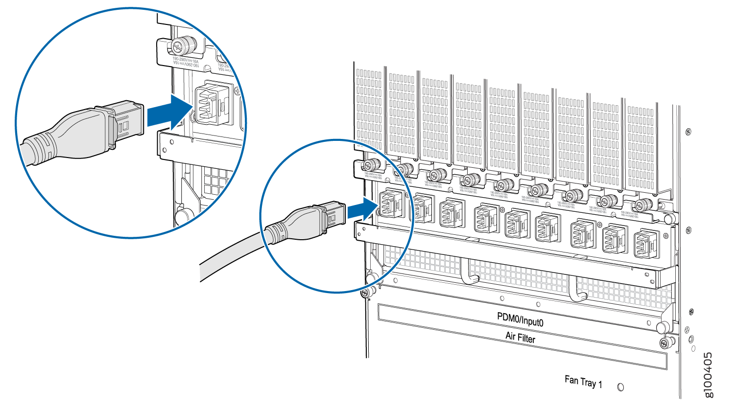
    Figure 2: Unplugging the 240 V China Power Cord an MX2000 Router
  4. Connect the power cords for the remaining PDMs.
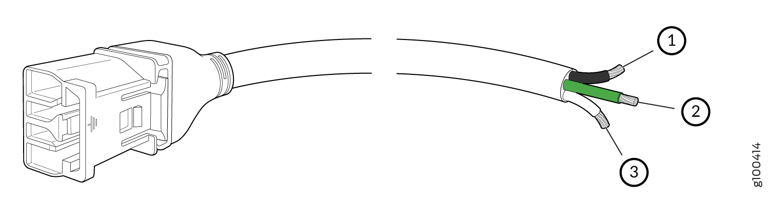
  5. Connect the power cable (CBL-PWR-240V-CH) to the DC power source. See Figure 3.
    Figure 3: 240 V China Power Cable240 V China Power Cable
      1

    Negative

      3

    Positive

      2

    Ground

     
  6. Switch on the dedicated customer site circuit breaker.
  7. On each of the DC power input sources, switch the DC circuit breaker to the center position before moving it to the ON position.
    Note:

    The circuit breaker may bounce back to the off position if you move the breaker too quickly.

  8. Observe the status LEDs on the PDM faceplate. If the PDM is correctly installed and functioning normally, the LEDs light green steadily.
  9. On each of the DC PSMs, move the switch to the on (|) position.