Mount the ME-X6
This topic guides you through the steps to mount your device on a two-post or four-post rack.
The mounting process is the same for both ME-X6 variants. The illustrations depict the ME-X6 variant 1.
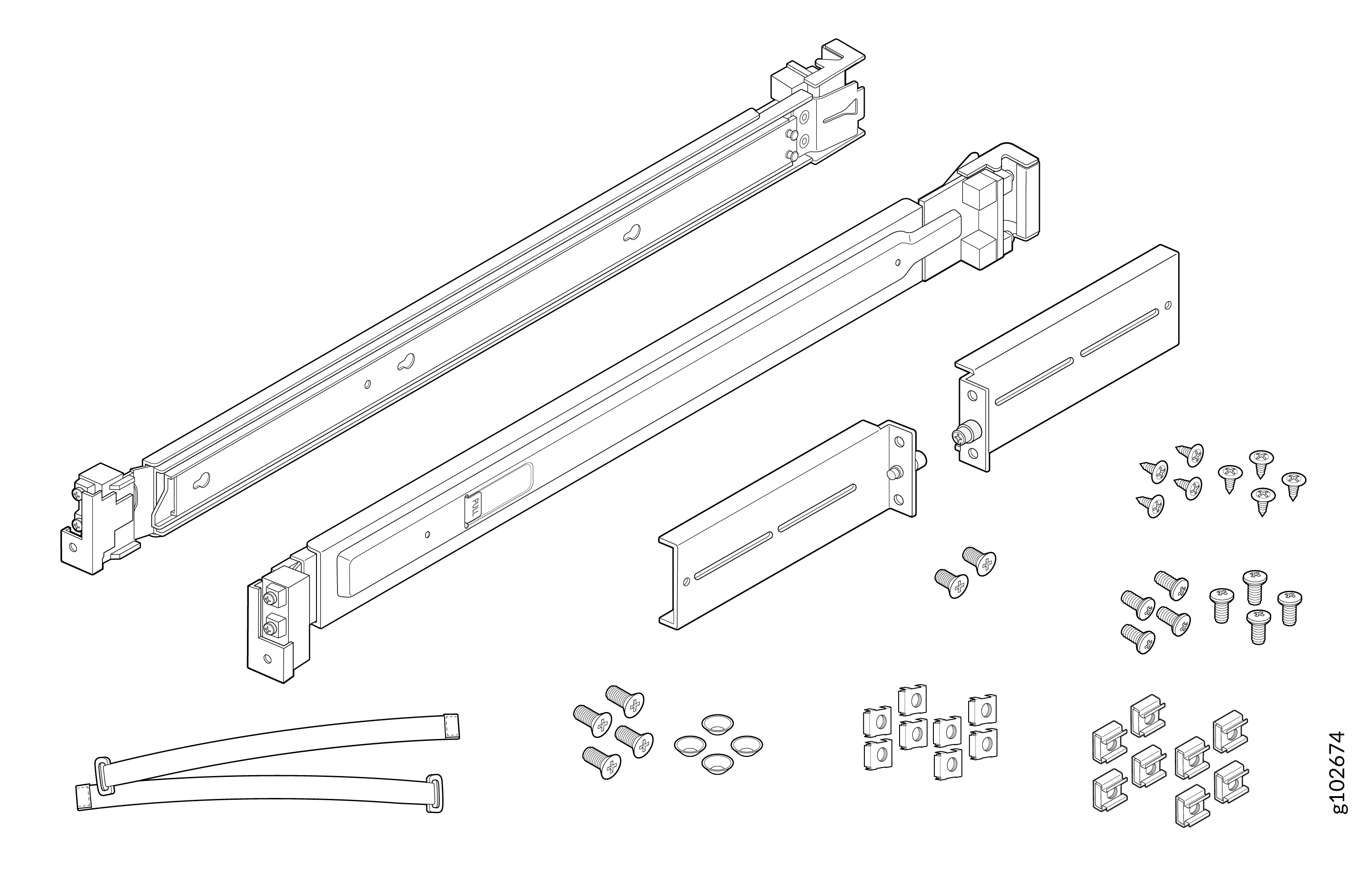
The rack mounting kit shipped with the ME-X6 contains the following parts:
-
Two rail mounting assemblies
-
Four L-brackets
-
Two screws to attach the mounting brackets to the device
-
Four screws to attach the mounting rail assemblies to the rack posts
-
Four conical washers
-
Eight screws to attach the L-brackets to the mounting rail assemblies
-
Eight screws to attach the L-brackets to the rack posts
-
Eight cage nuts
-
Eight square washers
-
Two cable management ties
Figure 1: Rack Mounting Kit Components
Mount Your Device on a Four-Post Rack
To mount your device on a four-post rack:
-
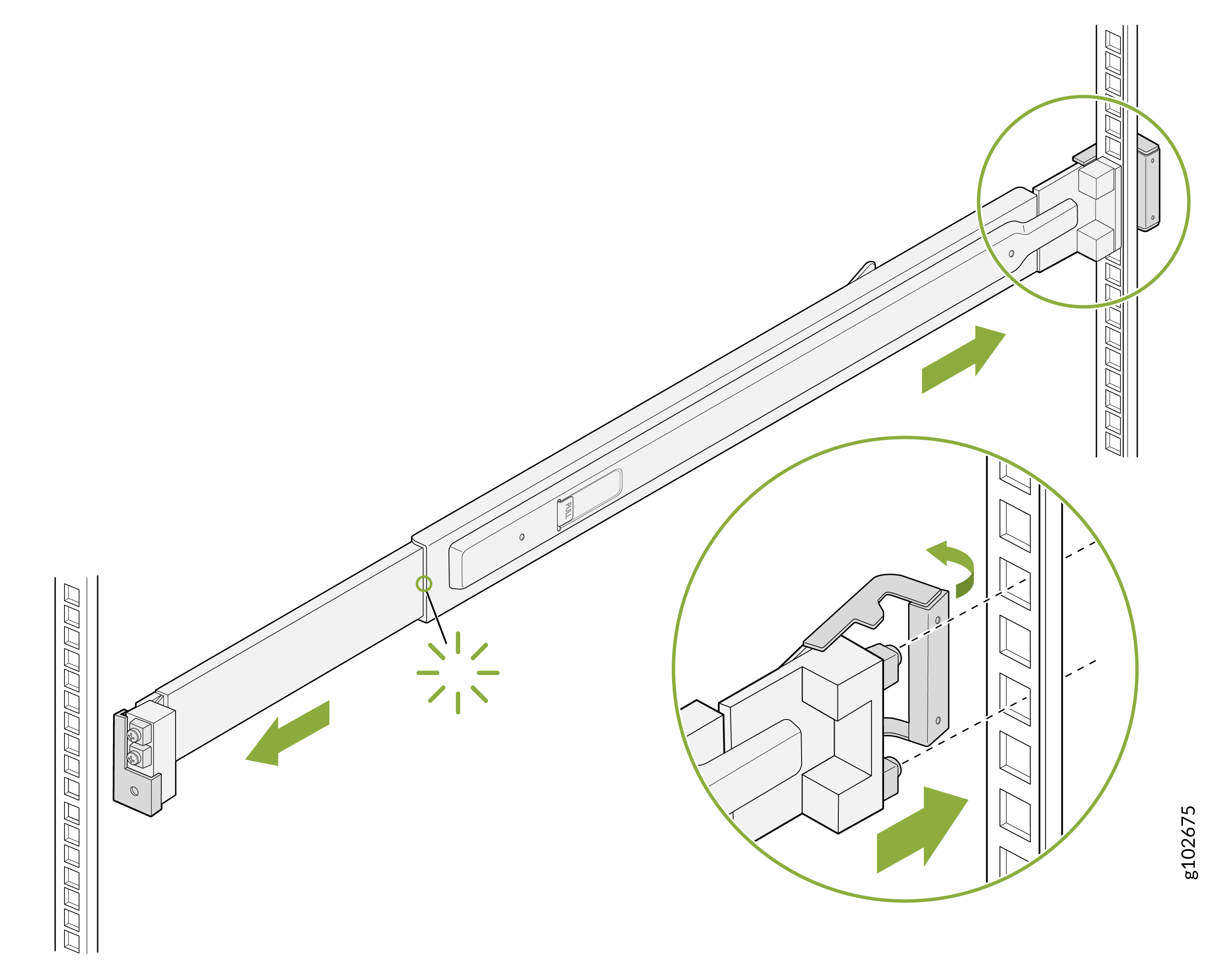
Open the latch on the rear rail of the mounting rail assembly. Align the guide blocks
on the rear rail with the rear-post holes. Push the rear rail toward the rear of the rack
so that the guide blocks slide into the rear-post holes. Lock the rear latch in
place.
Figure 2: Attach the Rear Rail
-
Open the latch on the front rail of the mounting rail assembly. Align the guide blocks
on the front rail with the front-post holes. Pull the front rail toward the front of the
rack so that the guide blocks slide into the front-post holes.
Figure 3: Attach the Front Rail
-
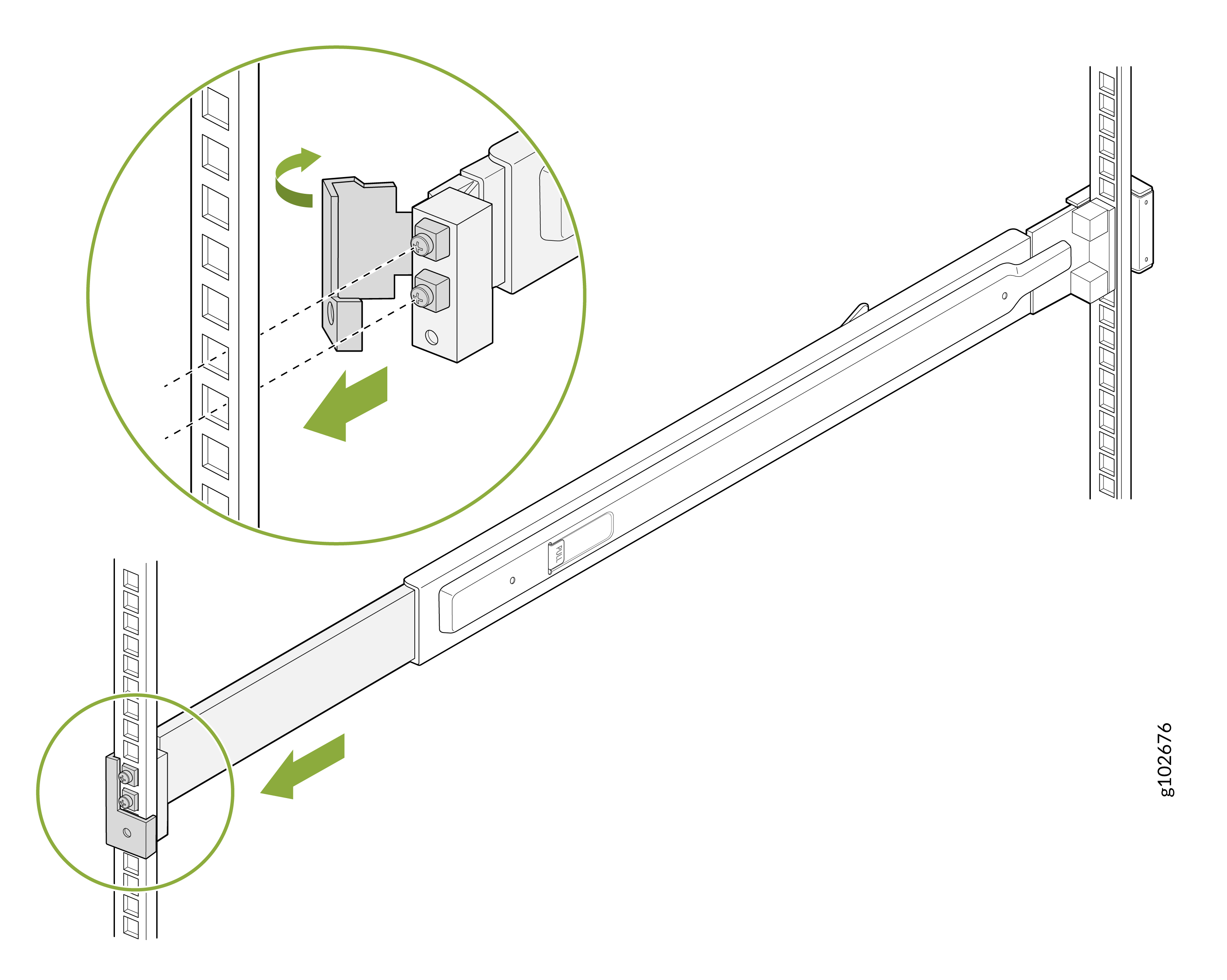
Secure the mounting rails to the rack posts using the supplied screws. Lock the front
latch in place.
Use the conical washers in case of a rack with square holes.Figure 4: Secure the Mounting Rails
-
Slide out the mounting rails fully. Press the latch on each rail and pull to remove
the innermost mounting brackets.
Figure 5: Remove the Mounting Brackets
-
Align the holes on each mounting bracket with the shoulder screws on the side of
the device. Attach the mounting brackets by sliding them toward the rear of the
device. Secure the mounting brackets to the device by using the provided
screws.
Figure 6: Attach the Mounting Brackets to the Device
-
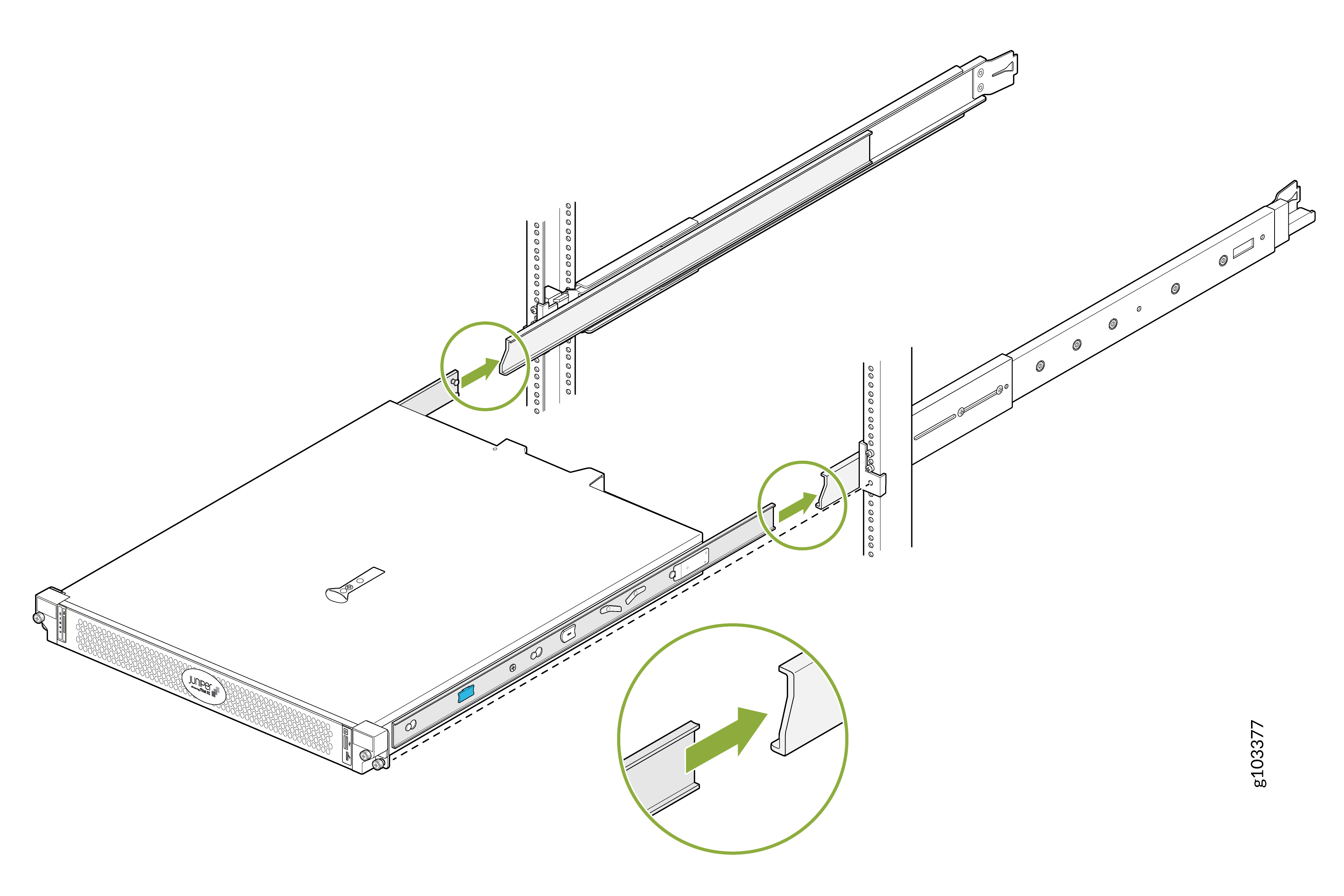
Lift the device and position it so that the mounting brackets are aligned with the
mounting rails. Slide the device into the channels of the mounting rails.
Figure 7: Slide the Device into the Mounting Rails
-
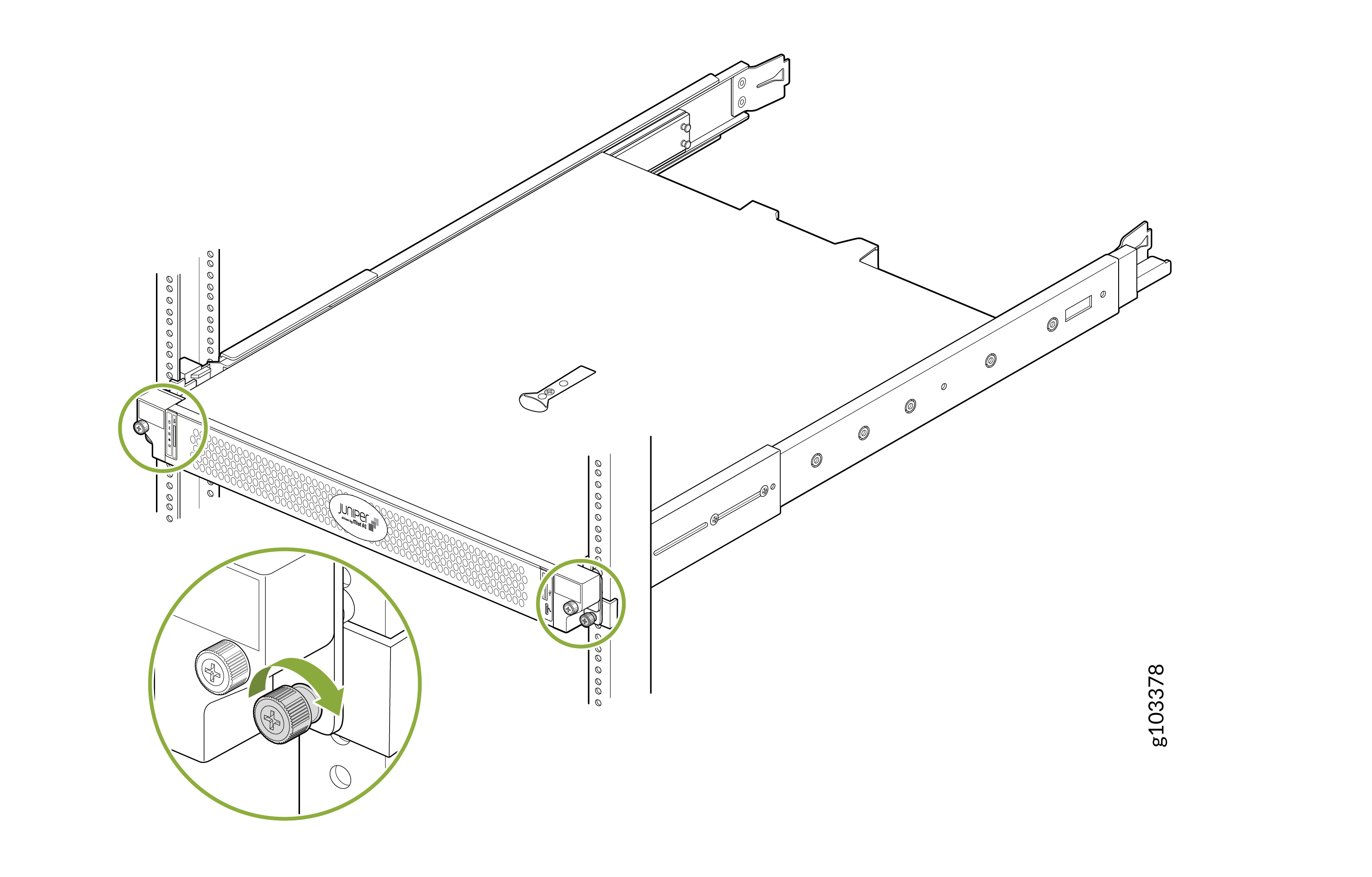
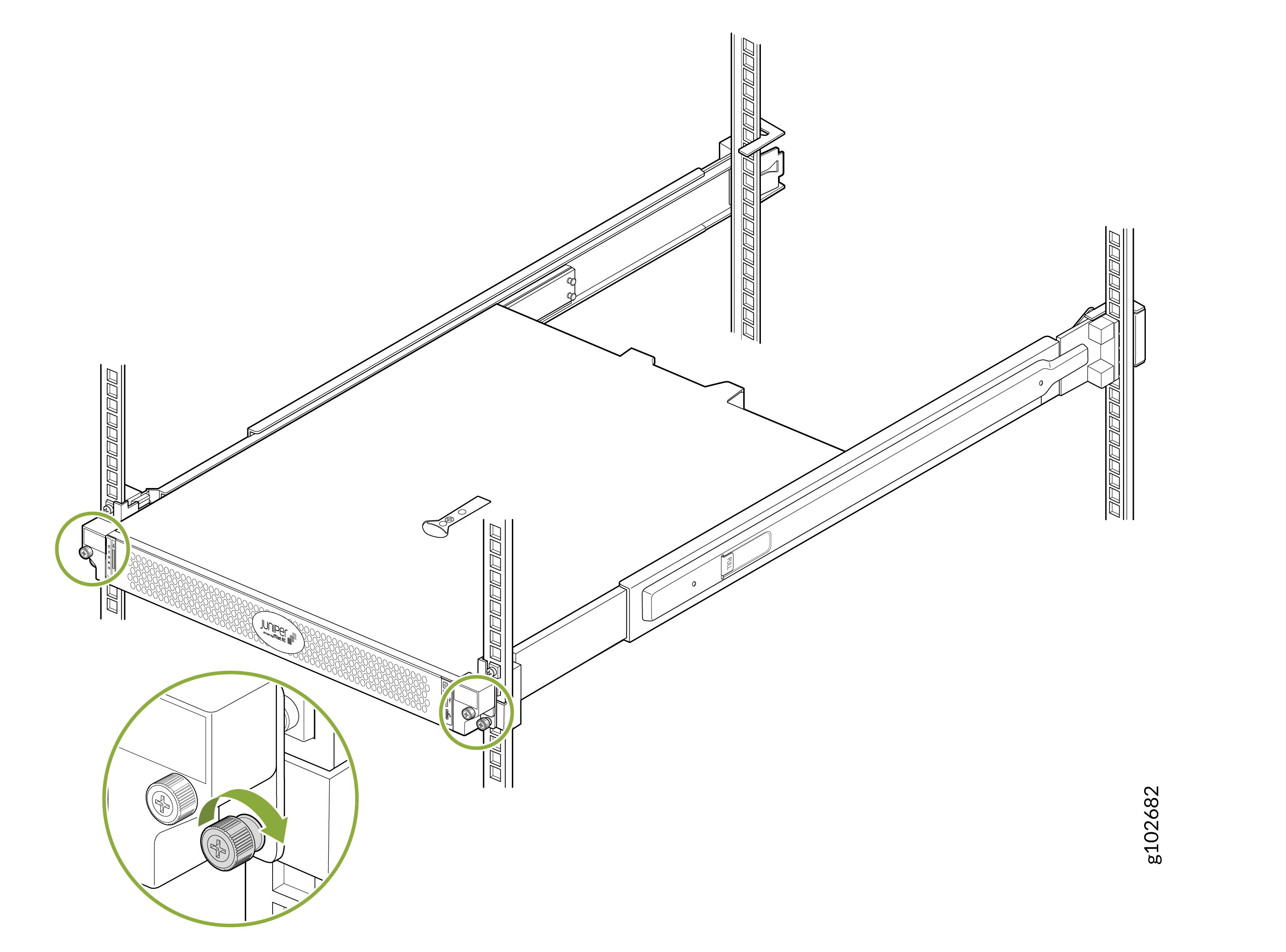
Tighten the screws on the front flanges of the device to secure it to the
rack.
Figure 8: Secure the Device
Mount Your Device on a Two-Post Rack (Center Mount)
To center mount your device on a two-post rack:
-
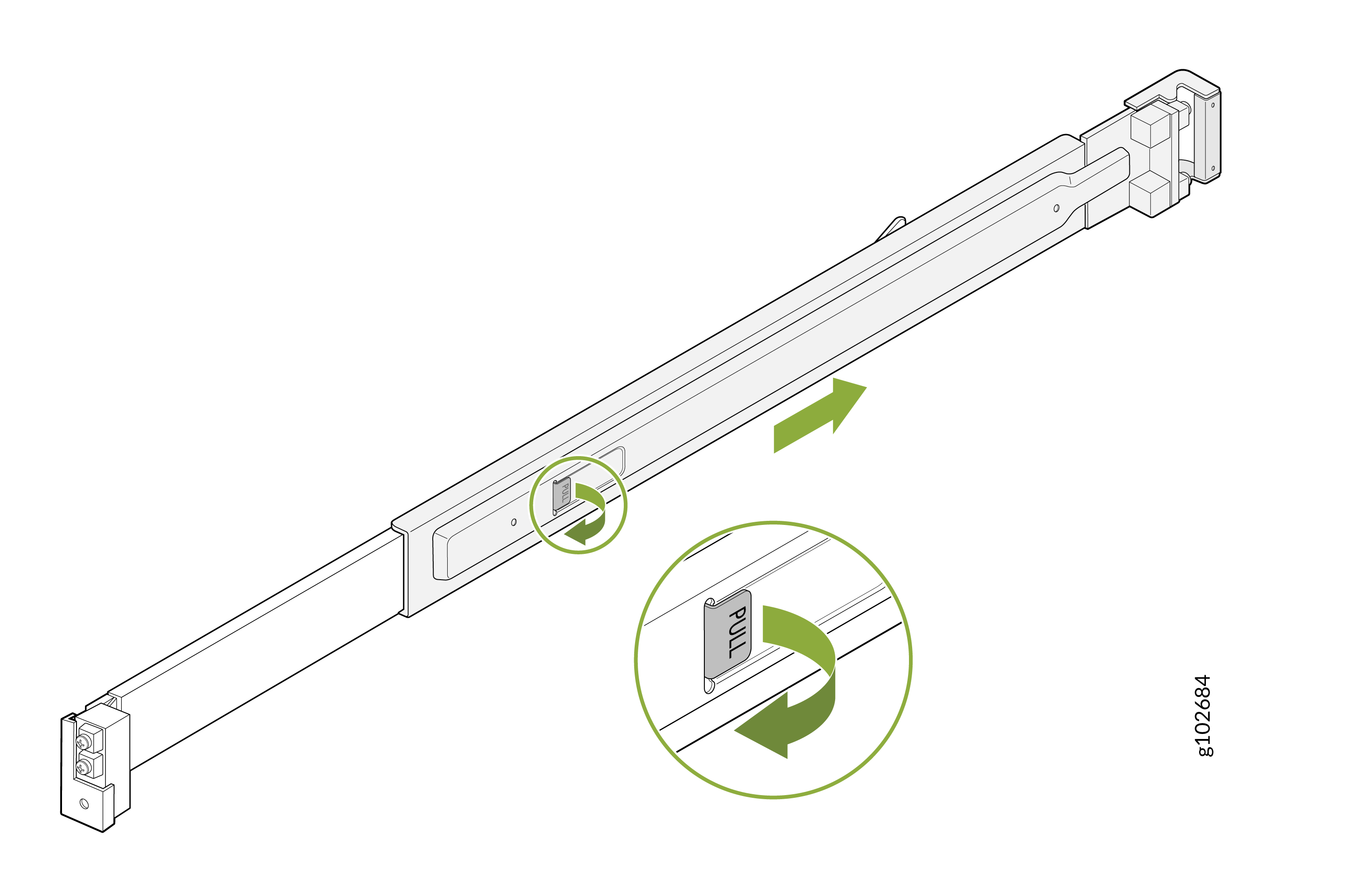
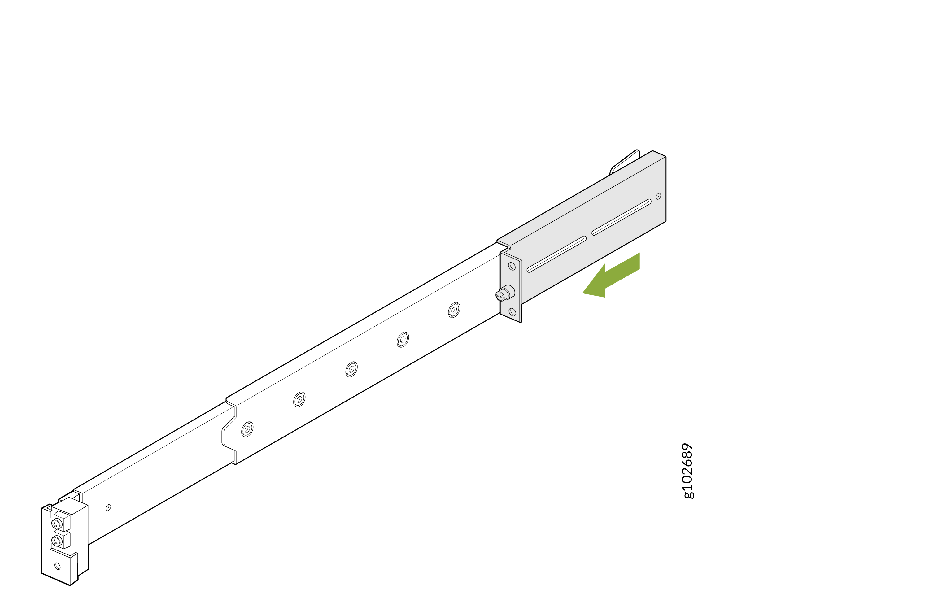
Pull the latch on the mounting rail assembly and slide out the rear rail.
Figure 9: Remove the Rear Rail
-
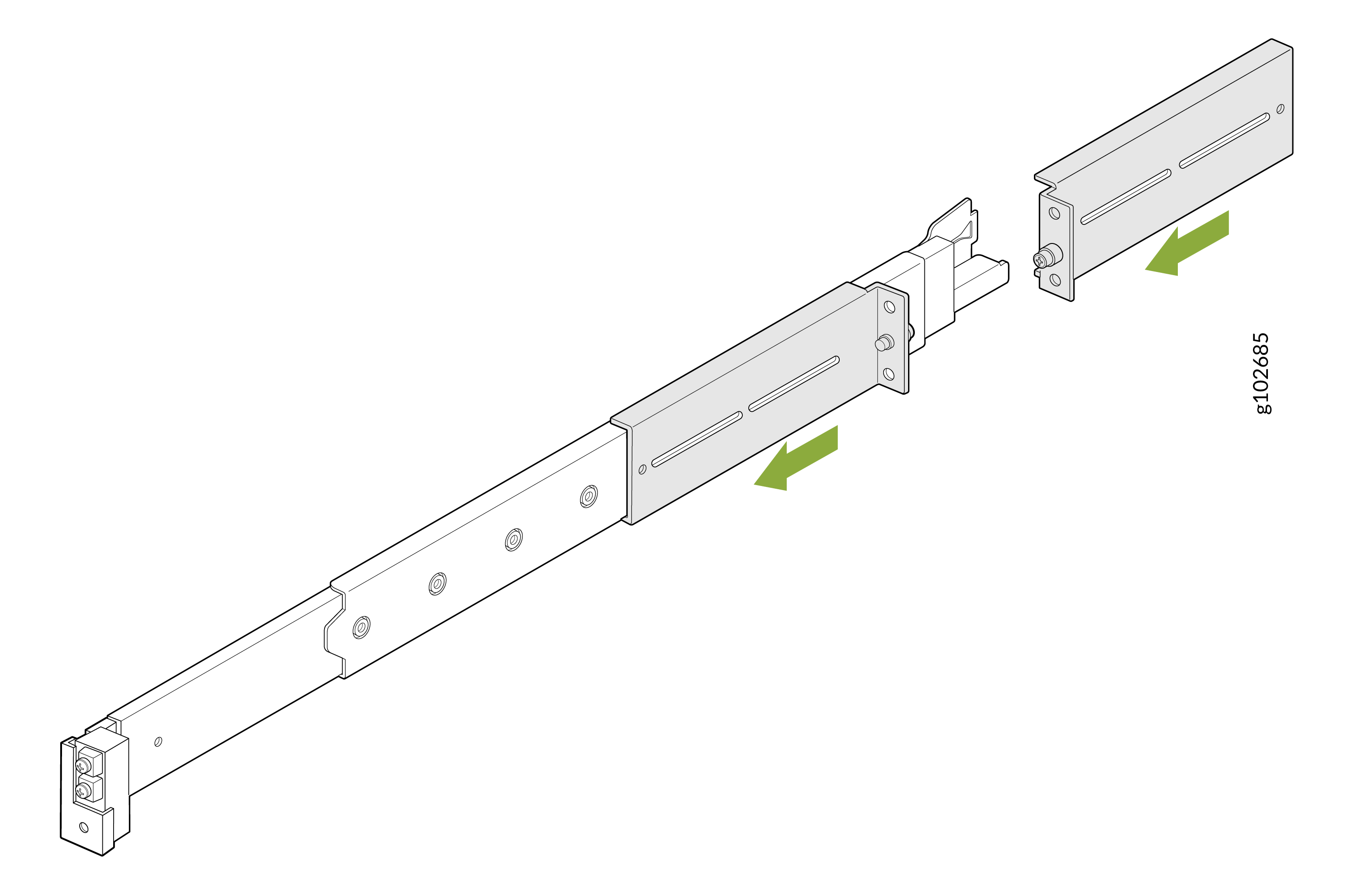
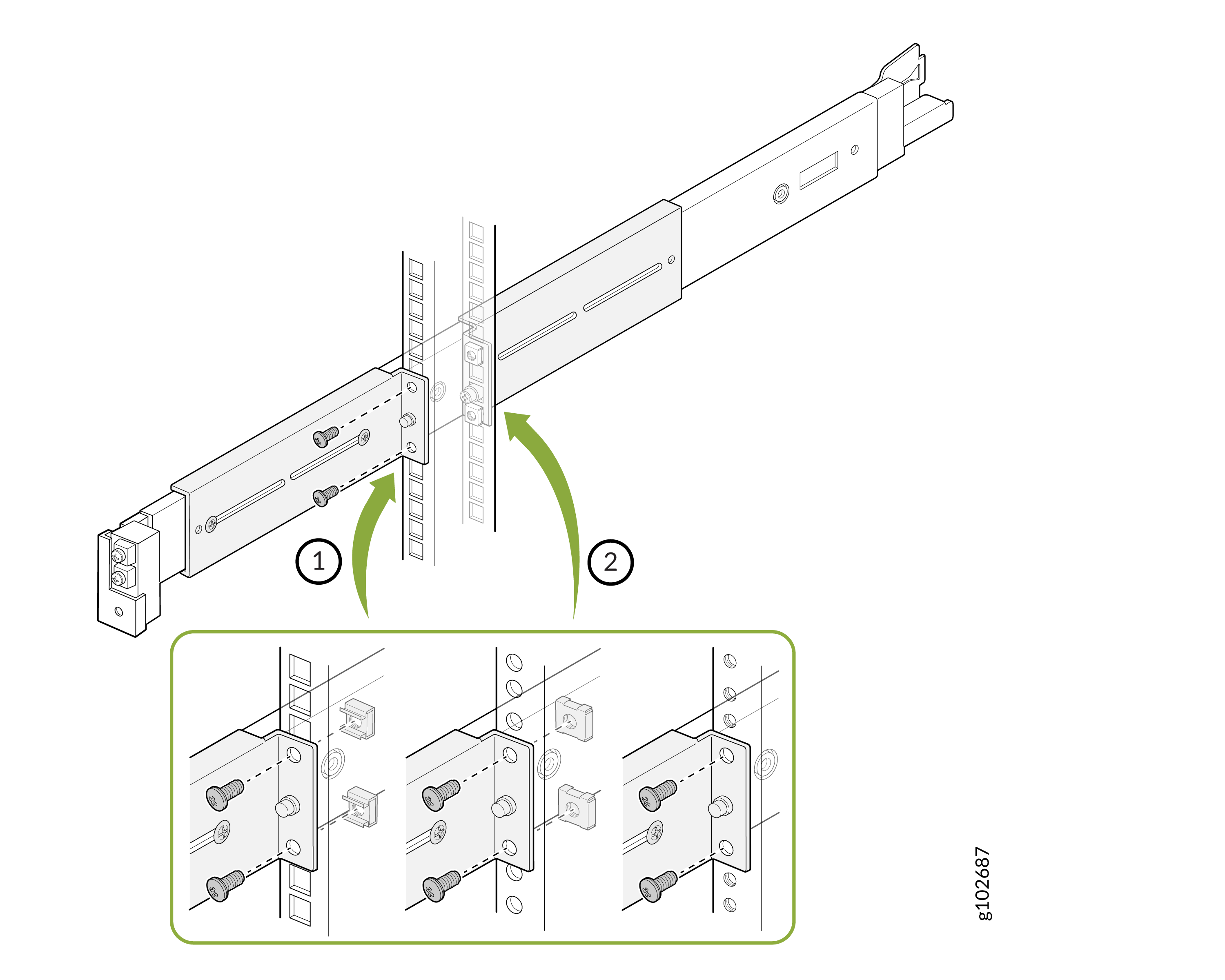
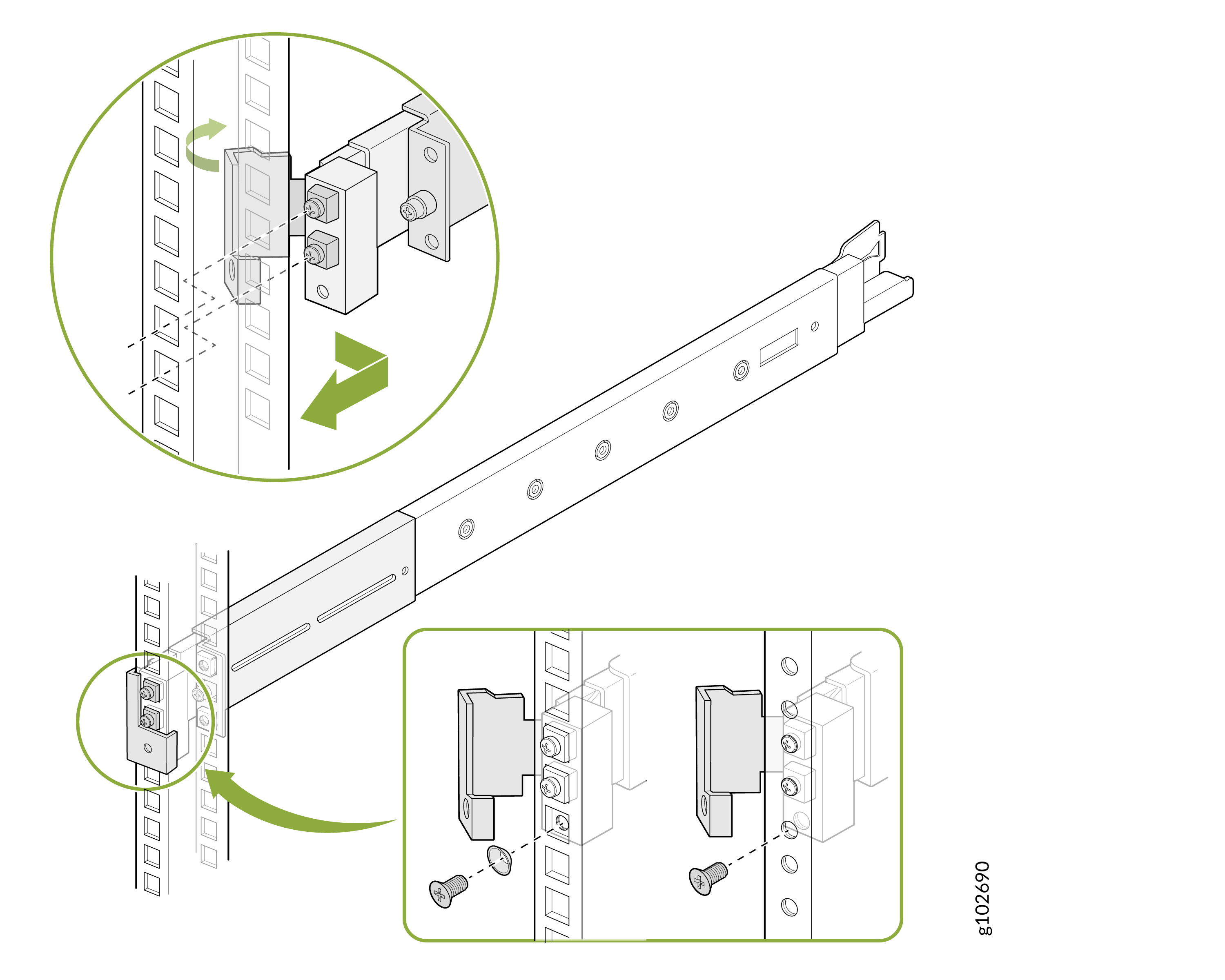
Slide the two L-brackets on to the front rail of the mounting rail assembly. Make sure
that the flanges of the L-brackets face each other.
Figure 10: Attach the L-Brackets
-
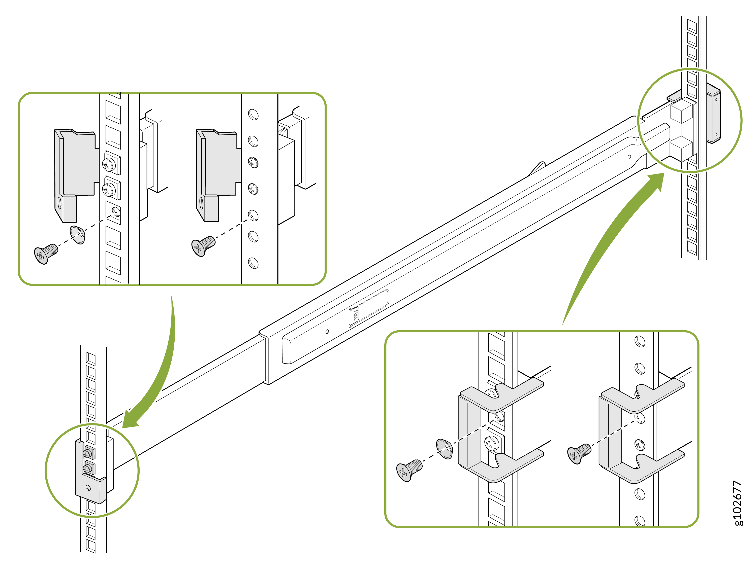
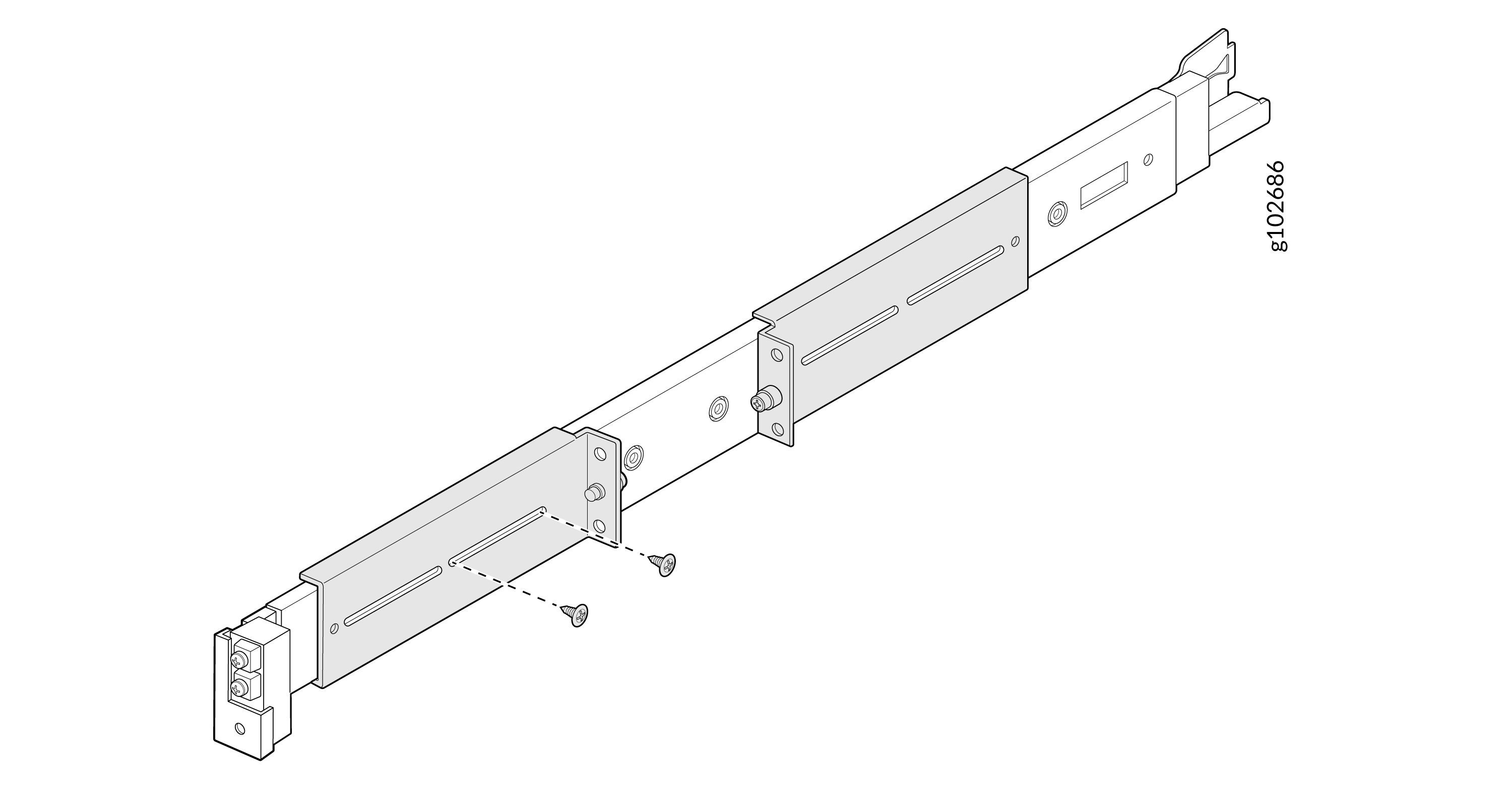
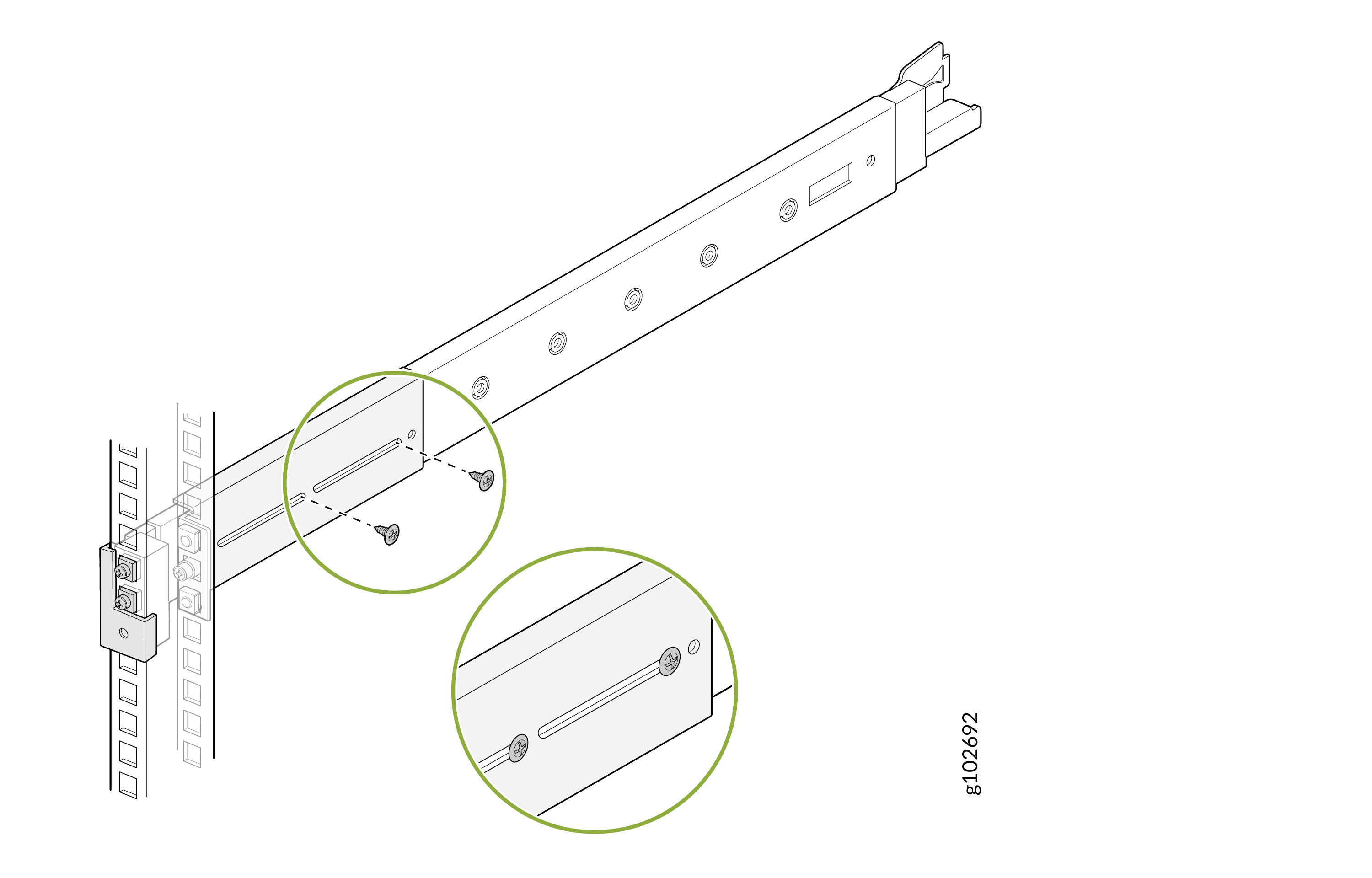
Secure the front L-bracket to the mounting rail assembly by using the provided
screws.
Figure 11: Secure the Front L-Bracket
-
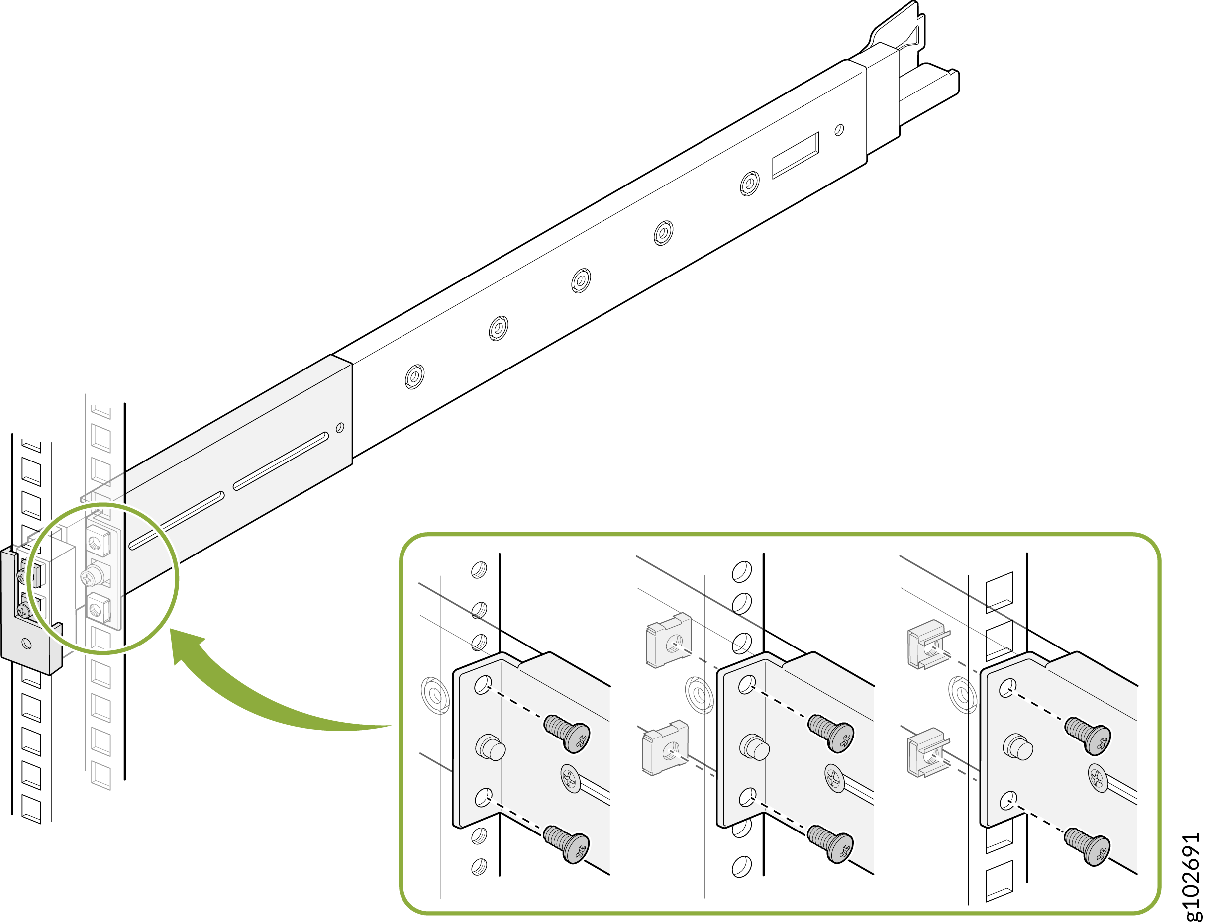
Attach the front and rear L-brackets to the rack post by using the provided screws and
washers.
Figure 12: Attach the L-Brackets to the Rack
-
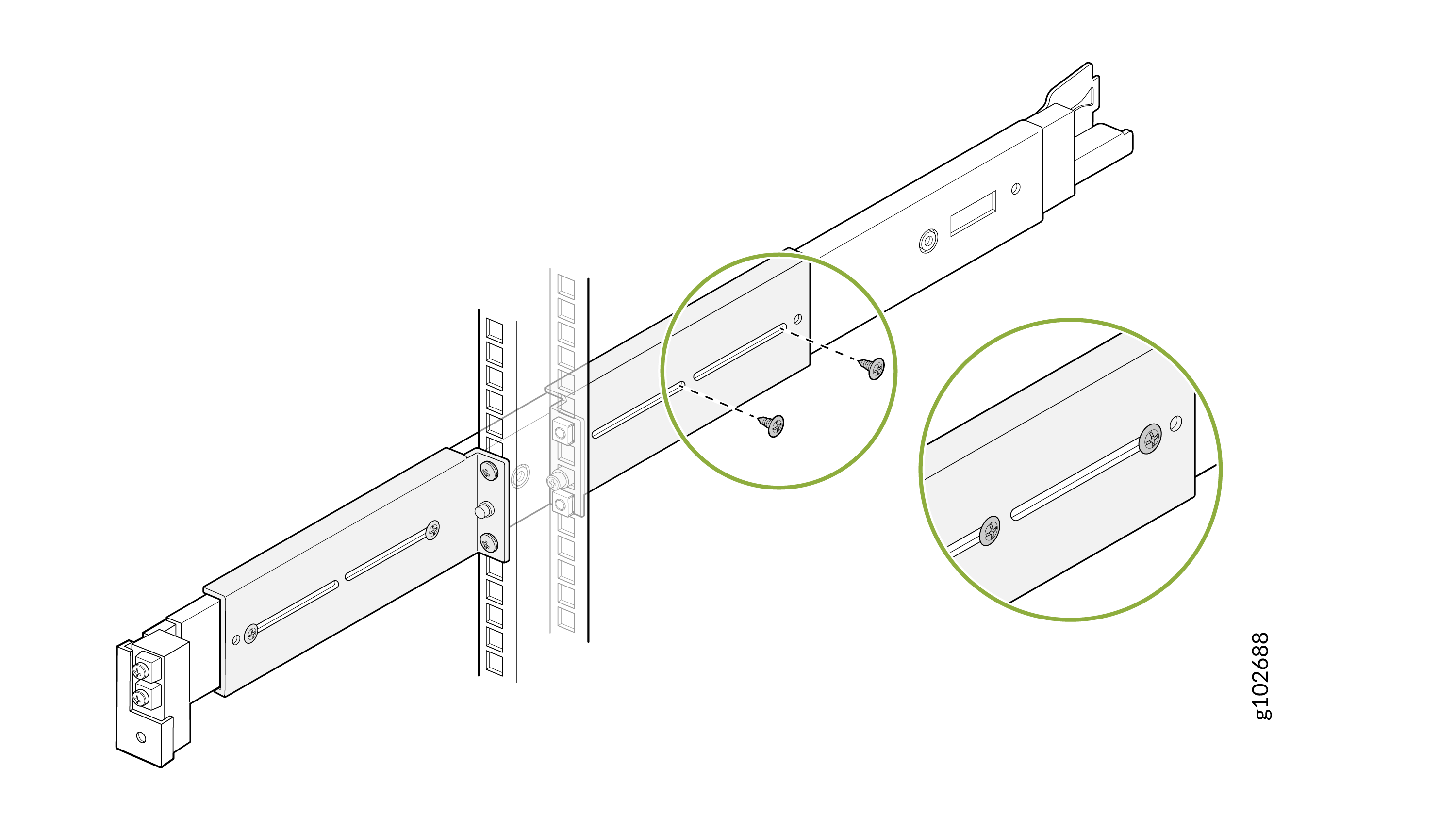
Secure the rear L-bracket to the mounting rail assembly by using the provided
screws.
Figure 13: Secure the Rear L-Bracket
-
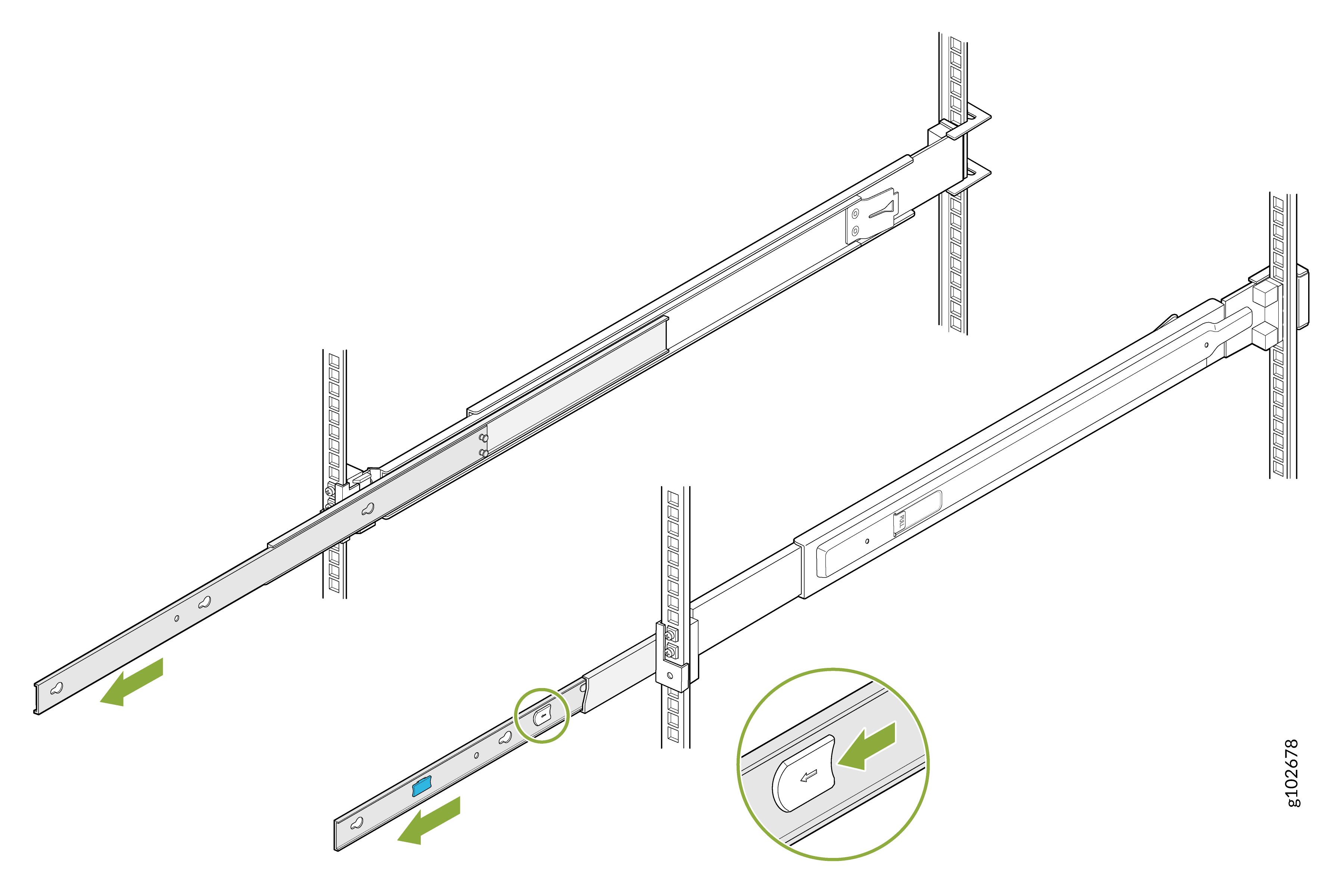
Slide out the mounting rails fully. Press the latch on each rail and pull to remove
the innermost mounting brackets.
Figure 14: Remove the Mounting Brackets
-
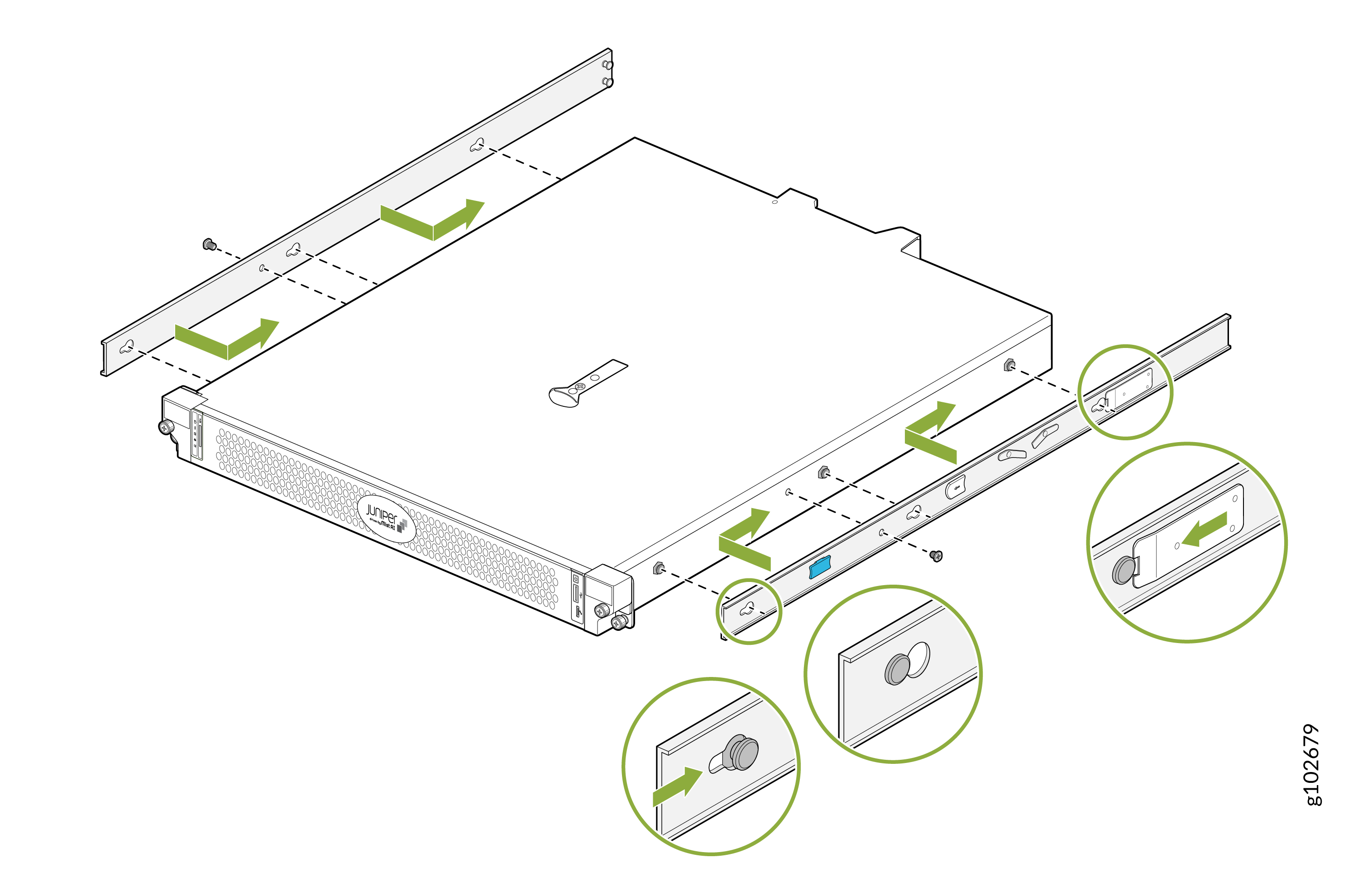
Align the holes on each mounting bracket with the shoulder screws on the side of
the device. Attach the mounting brackets by sliding them toward the rear of the
device. Secure the mounting brackets to the device by using the provided
screws.
Figure 15: Attach the Mounting Brackets to the Device
-
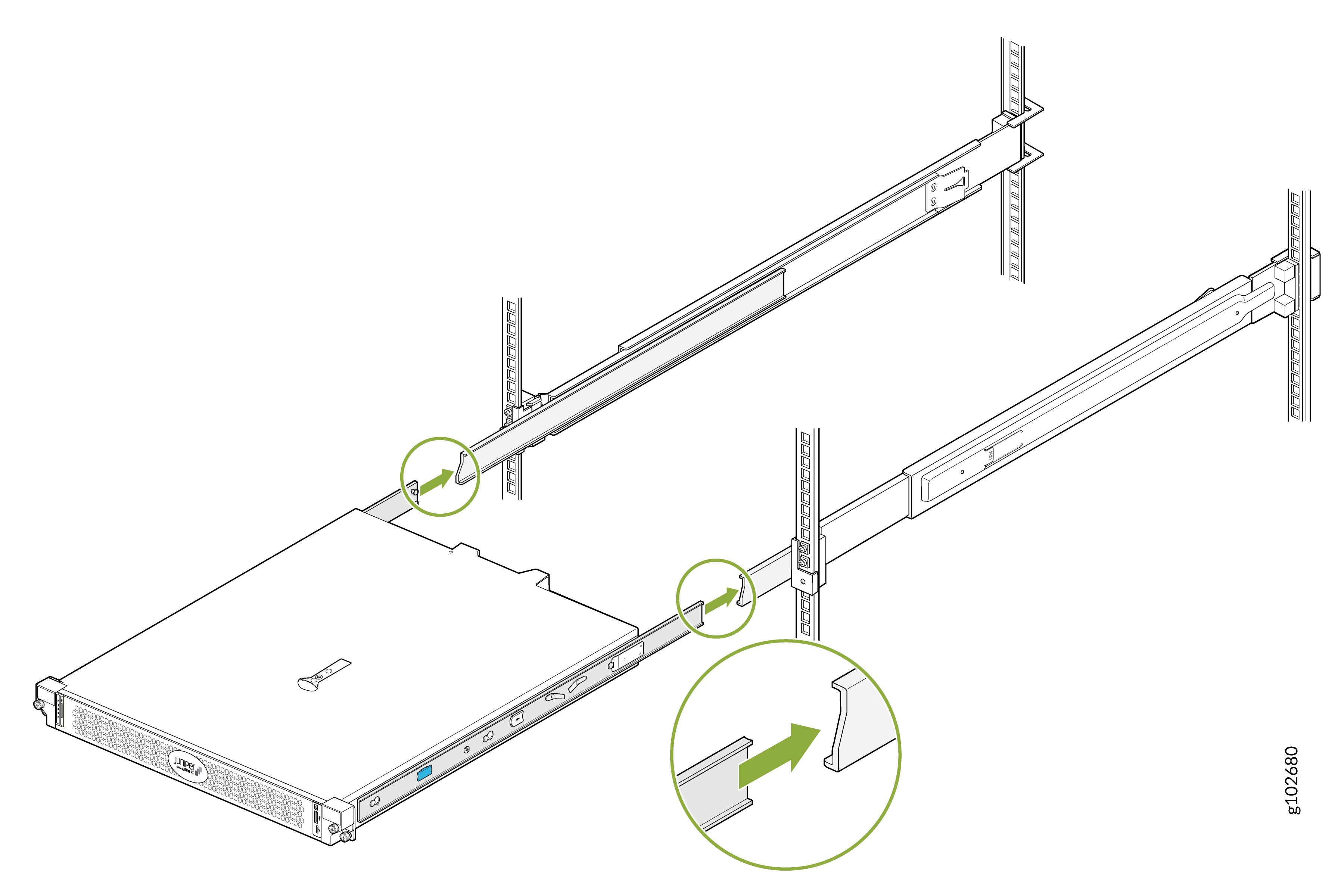
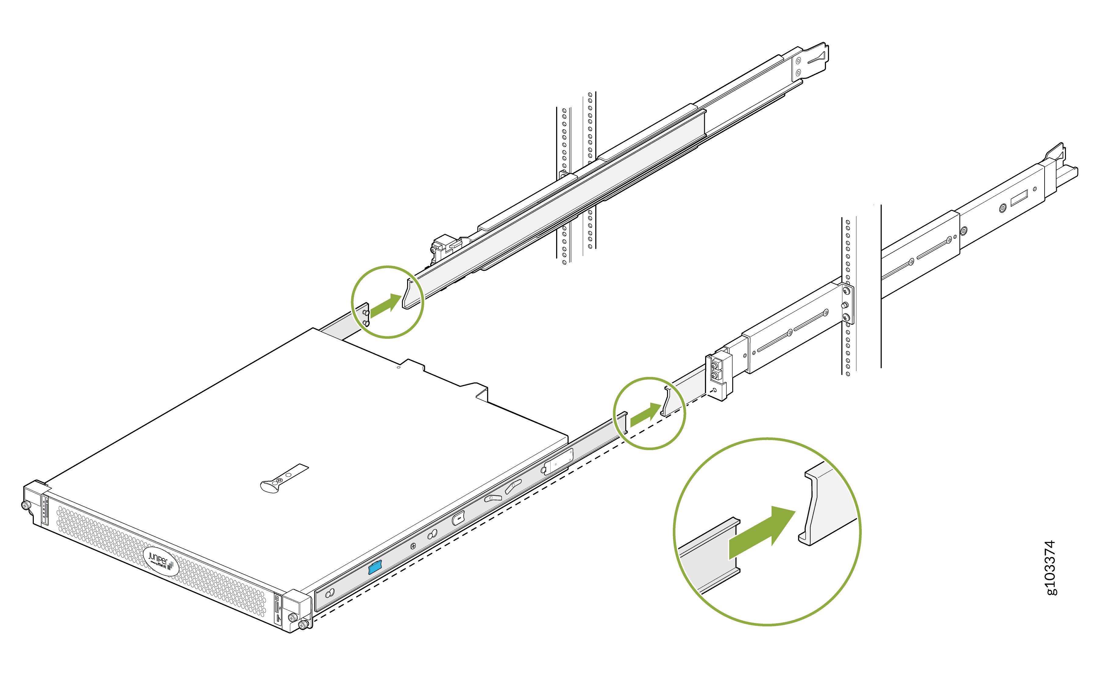
Lift the device and position it so that the mounting brackets are aligned with the
mounting rails. Slide the device into the channels of the mounting rails.
Figure 16: Slide the Device into the Mounting Rails
-
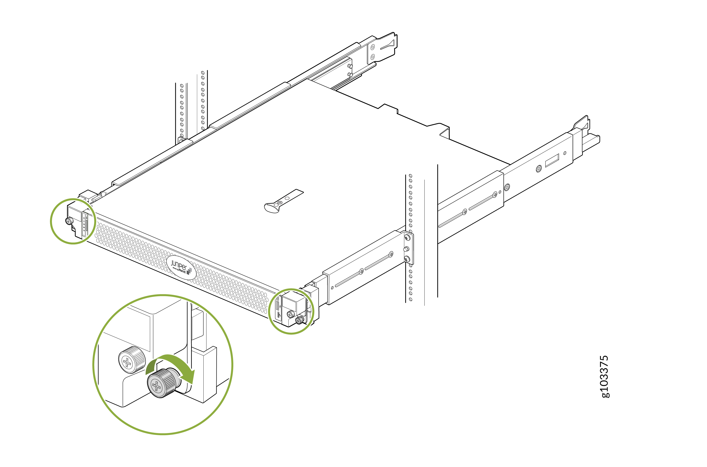
Tighten the screws on the front flanges of the device to secure it to the
rack.
Figure 17: Secure the Device
Mount Your Device on a Two-Post Rack (Flush Mount)
To flush mount your device on a two-post rack:
-
Pull the latch on the mounting rail assembly and slide out the rear rail.
Figure 18: Remove the Rear Rail
-
Slide an L-bracket on the mounting rail assembly so that the flange faces the front of
the rack.
Figure 19: Attach the L-Bracket
-
Open the latch on the front rail of the mounting rail assembly. Align the guide blocks
on the front rail with the front-post holes. Pull the front rail toward the front of the
rack so that the guide blocks slot into the front-post holes. Secure the front rail using
the provided screws and conical washers. Lock the latch.
Figure 20: Attach the Front Rail
-
Secure the L-bracket to the rack post by using the provided screws and washers.
Figure 21: Attach the L-Bracket to the Rack Post
-
Secure the L-bracket to the mounting rail assembly by using the provided screws.
Figure 22: Attach the L-Bracket to the Mounting Rail Assembly
-
Slide out the mounting rails fully. Press the latch on each rail and pull to remove
the innermost mounting brackets.
Figure 23: Remove the Mounting Brackets
-
Align the holes on each mounting bracket with the shoulder screws on the side of
the device. Attach the mounting brackets by sliding them toward the rear of the
device. Secure the mounting brackets to the device by using the provided
screws.
Figure 24: Attach the Mounting Brackets to the Device
-
Lift the device and position it so that the mounting brackets are aligned with the
mounting rails. Slide the device into the channels of the mounting rails.
Figure 25: Slide the Device into the Mounting Rails
-
Tighten the screws on the front flanges of the device to secure it to the
rack.
Figure 26: Secure the Device