ME-X6 Chassis
The front and rear panels of the ME-X6 variant 1 and variant 2 are different. See below for a detailed list of differences.
ME-X6 Front Panel
A front bezel covers the front panel of the ME-X6. Remove the front bezel to access the front panel. The front panel of both variants is the same.
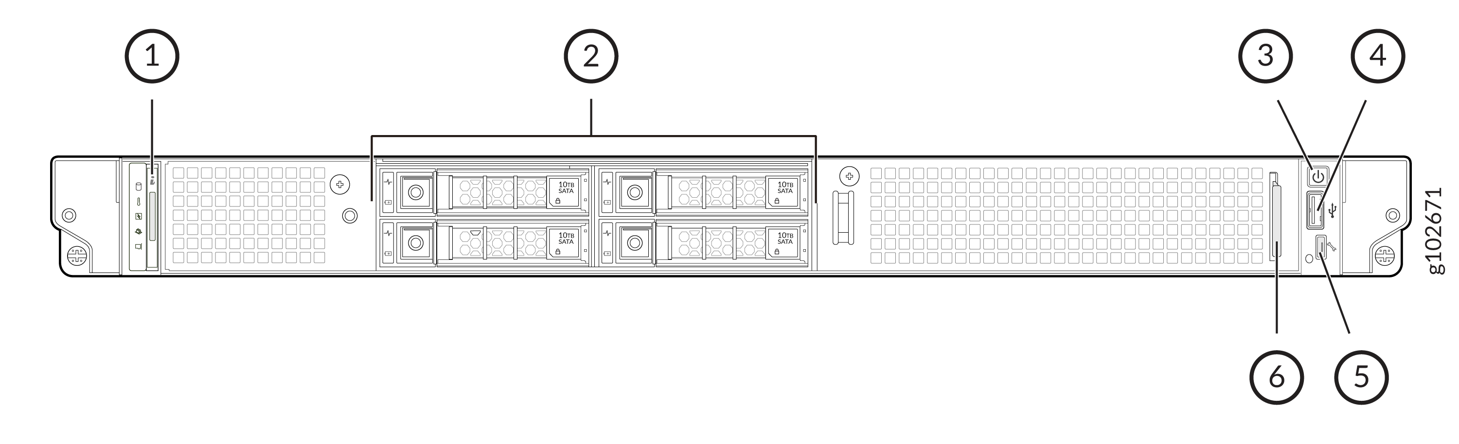
| Callout | Component | Description |
|---|---|---|
|
1 |
Status LED control panel |
Indicates status of the device and its components |
|
2 |
Storage drives |
Used for data storage |
|
3 |
Power button |
Used to manually power on or power off the device |
|
4 |
USB 2.0 port |
Used to connect USB devices |
|
5 |
iDRAC direct port |
Micro-AB type USB port to access the iDRAC The LED next to the port indicates the device connection status.
|
|
6 |
Information tab |
Contains the serial number, Juniper Mist claim code, and iDRAC password |
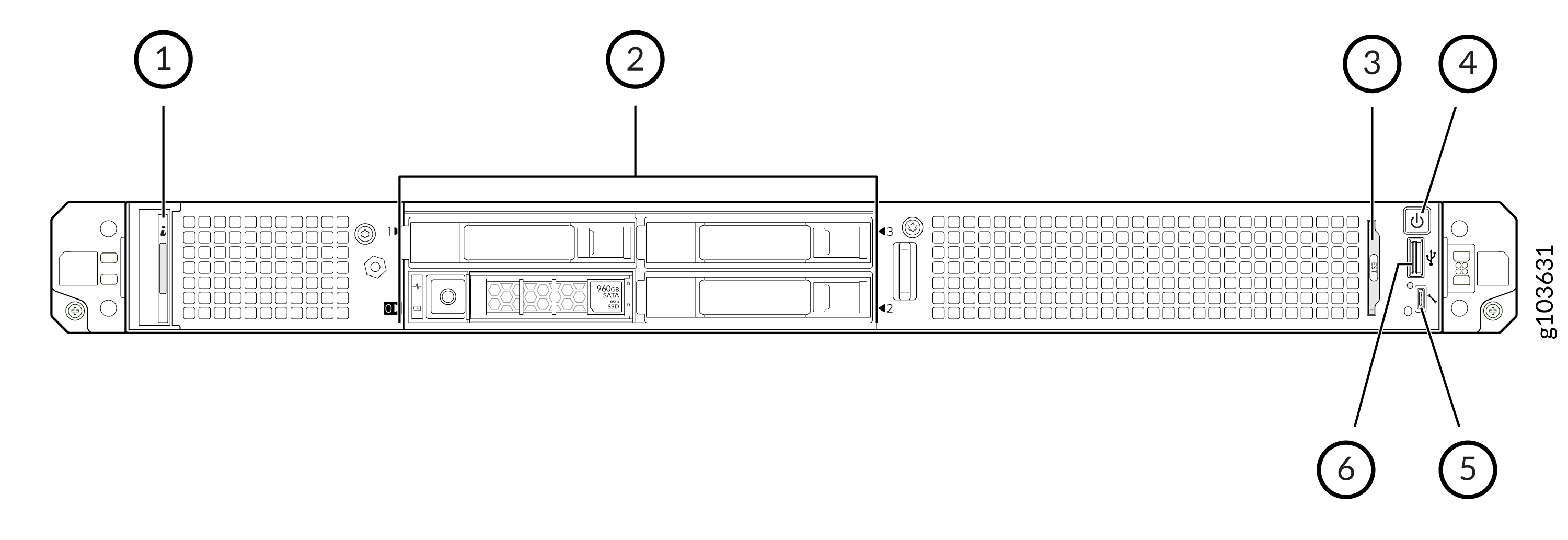
| Callout | Component | Description |
|---|---|---|
|
1 |
Status LED control panel |
Indicates status of the device and its components |
|
2 |
Storage drives |
Used for data storage |
|
3 |
Information tab |
Contains the serial number, Juniper Mist claim code, and iDRAC password |
|
4 |
Power button |
Used to manually power on or power off the device |
|
5 |
iDRAC direct port |
Micro-AB type USB port to access the iDRAC The LED next to the port indicates the device connection status.
|
|
6 |
USB 2.0 port |
Used to connect USB devices |
Status LEDs on the ME-X6
The status LED control panel is located at the front of the device. You can see the status LEDs without removing the front bezel. The status panel for both variants is the same.
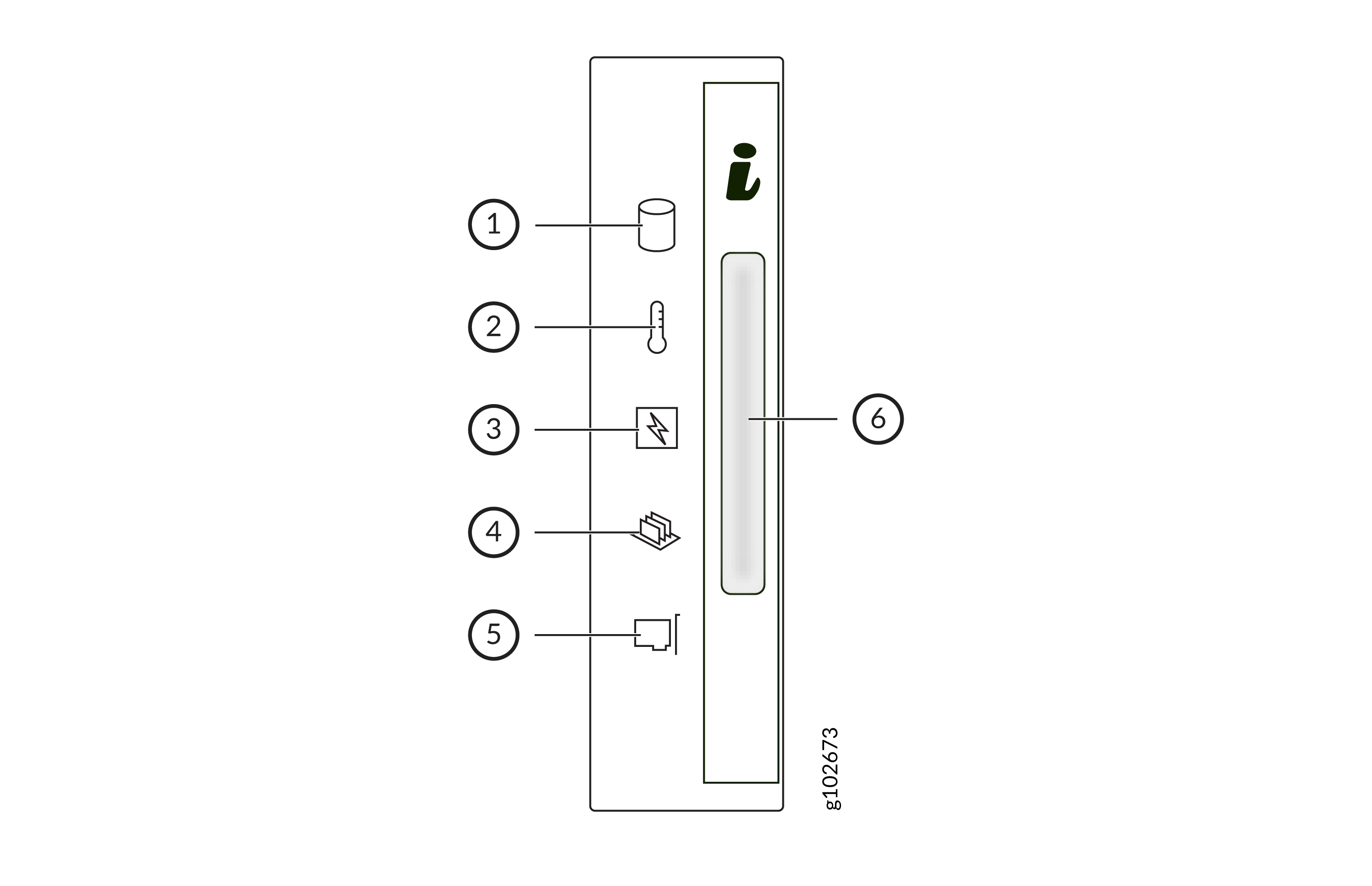
| Callout | Component | Color | Description |
|---|---|---|---|
|
1 |
Drive indicator |
Solid amber |
The system has detected a drive error. To address the error:
|
|
2 |
Temperature indicator |
Solid amber |
The system has detected a thermal error that is caused by any one of these issues:
|
|
3 |
Electrical indicator |
Solid amber |
The system has detected an electrical error. To address the error:
|
|
4 |
Memory indicator |
Solid amber |
The system has detected a memory error. To address the error:
|
|
5 |
PCI Express indicator |
Solid amber |
The system has detected an error in the PCI Express card. Restart the device. Update any required drivers for the PCI Express card. Reinstall the card. |
|
6 |
System health and system ID indicator |
Solid blue |
The device is powered on and healthy, and the system ID mode is not active. |
|
Blinking blue |
The system ID mode is active. Note:
Press the system health and system ID button to switch between system ID mode and system health mode. |
||
|
Solid amber |
The device is in fail-safe mode. |
||
|
Blinking amber |
The device is experiencing a fault. Check the device event logs for more details. |
Storage Drive LEDs

| Callout | LED | Color | Description |
|---|---|---|---|
| 1 |
Link LED |
Solid green |
The drive is online. |
|
Blinking green |
The drive is being identified or is being prepared for removal. |
||
|
Blinking green slowly |
The drive is being rebuilts. |
||
|
Blinking green, amber, and then off |
An unexpected drive failure has occurred. |
||
|
Blinking green for three seconds, amber for three seconds, and then off |
The drive rebuild has stopped. |
||
|
Blinking amber |
The drive has failed. |
||
|
Off |
The drive is ready for removal. |
||
| 2 |
Activity LED |
Blinking green |
The drive is being accessed. |
|
Off |
There is no drive activity. |
ME-X6 Rear Panel
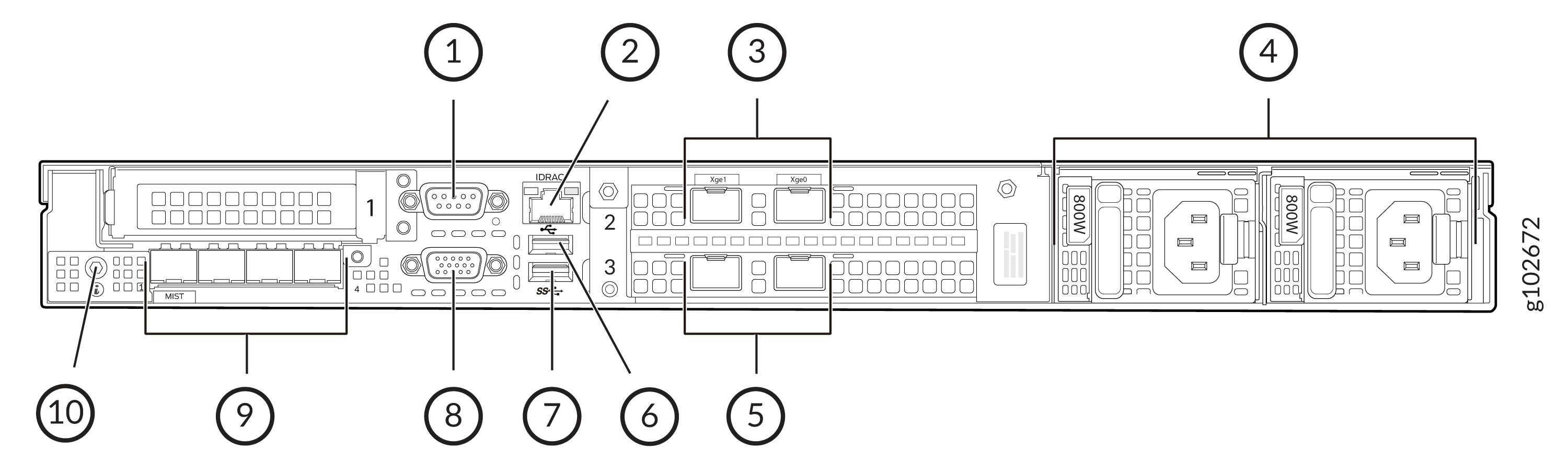
| Callout | Component | Description |
|---|---|---|
|
1 |
Serial port |
Used to connect a serial device |
|
2 |
iDRAC dedicated port |
Used to remotely access iDRAC |
|
3 and 5 |
Data ports |
Four 25-GbE SFP28 ports They act as the endpoint for tunnels from the APs. |
|
4 |
PSUs |
Two 800-W AC PSUs |
|
6 |
USB 2.0 port |
Used to connect USB devices |
|
7 |
USB 3.0 port |
Used to connect USB devices |
|
8 |
VGA port |
Used to connect a display device |
|
9 |
Management ports |
Four 25-GbE SFP28 management ports The first one, labeled MIST is used for out-of-band management (OOBM). |
|
10 |
System identification button |
|
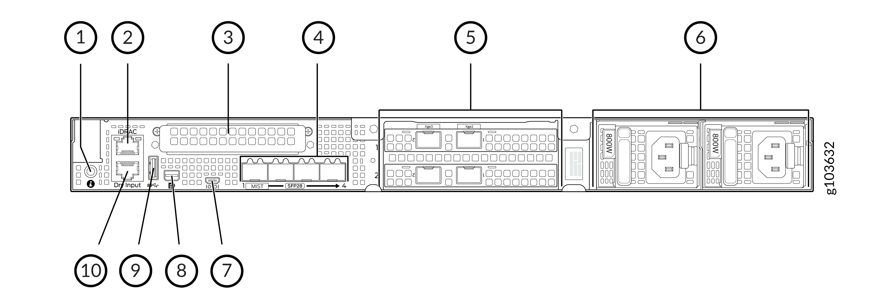
| Callout | Component | Description |
|---|---|---|
|
1 |
System identification button |
|
|
2 |
iDRAC dedicated port |
Used to remotely access iDRAC |
|
3 |
Management ports |
Four 25-GbE SFP28 management ports The first one, labeled MIST is used for out-of-band management (OOBM). |
|
4 |
Data ports |
Four 25-GbE SFP28 ports They act as the endpoint for tunnels from the APs. |
|
5 |
PSUs |
Two 800-W AC PSUs |
|
6 |
Serial port |
Used to connect a serial device |
|
7 |
Mini-display port |
Used to connect a display device |
|
8 |
USB 3.0 port |
Used to connect USB devices |
|
9 |
Dry port |
An RJ-45 port used to provide interruptible inputs to iDRAC. |
Data Port LEDs
| Link LED indicator | Activity LED indicator | Description |
|---|---|---|
|
Off |
Off |
Port is not connected to the network. |
|
Solid green |
Blinking green |
Port is connected to the network at the maximum port speed and has link activity. |
|
Off |
Port is connected to the network at the maximum port speed and has no link activity. |
|
|
Solid amber |
Blinking green |
Port is connected to the network at less than the maximum port speed and has link activity. |
|
Off |
Port is connected to the network at less than the maximum port speed and has no link activity. |
|
|
Blinking green |
Off |
Port identity is enabled through the NIC configuration utility. |
Management Port LEDs
| Link LED indicator | Activity LED indicator | Description |
|---|---|---|
|
Off |
Off |
Port is not connected to the network. |
|
Solid green |
Blinking green |
Port is connected to the network at the maximum port speed and has link activity. |
|
Off |
Port is connected to the network at the maximum port speed and has no link activity. |
|
|
Solid amber |
Blinking green |
Port is connected to the network at less than the maximum port speed and has link activity. |
|
Off |
Port is connected to the network at less than the maximum port speed and has no link activity. |
|
|
Blinking green |
Off |
Port identity is enabled through the NIC configuration utility. |
Power Supply LEDs
The PSUs have an illuminated translucent handle that acts as an indicator.
| LED color | Description |
|---|---|
|
Solid green |
The PSU is operational. |
|
Blinking green |
The pPSU firmware is being updated. |
|
Blinking green and then off |
A PSU is being installed while the device is running. It indicates a PSU mismatch due to efficiency, feature set, health status, or supported voltage. |
|
Blinking amber |
The device faces an issue with the PSU. |
|
Off |
The PSU is not connected to the power source. |
Internal View of the ME-X6
You can remove the cover panel to access the inside of the ME-X6. We do not recommend opening up the device unless for maintenance purposes.
The internal components for both variants are the same.
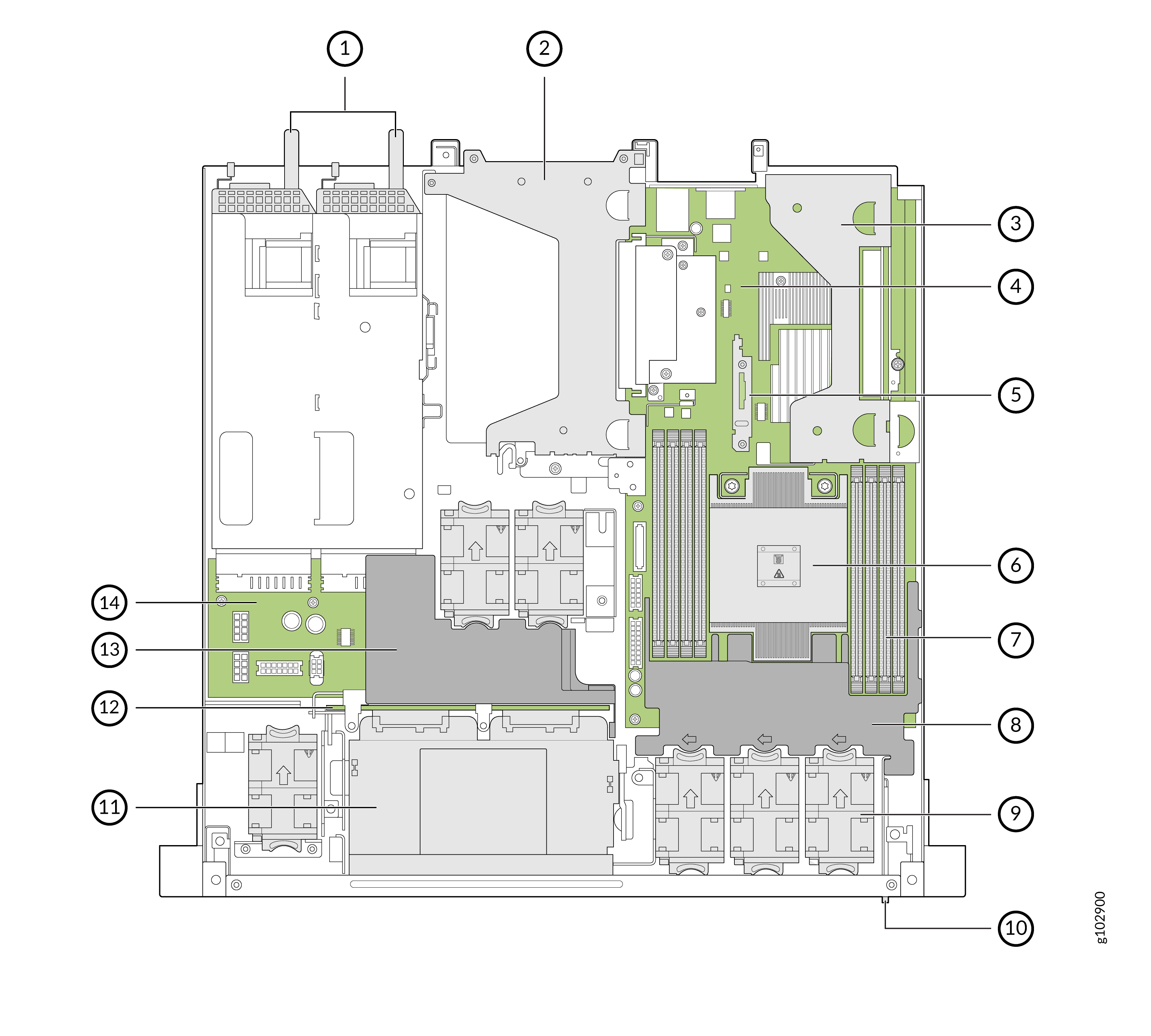
| Calllout | Component |
|---|---|
|
1 |
Power supply units |
|
2 |
Riser 2 and 3 |
|
3 |
Riser 1 |
|
4 |
System board |
|
5 |
BOSS-S1 card |
|
6 |
Processor and heat sink |
|
7 |
Memory module slots |
|
8 |
Processor air shroud |
|
9 |
Cooling fans |
|
10 |
Information tag |
|
11 |
Drive cage |
|
12 |
Backplane |
|
13 |
PCI air shroud |
|
14 |
Power Interposer Board |