LWC Chassis
Front Panel of an LWC Device
The LWC does not use all the ports available on its front panel. It uses only the following ports:
- One 1GbE RJ-45 network port (port 0, interface name ge-0/0/0) used to access the captive portal (for configuration and diagnostics)
- Two 1GbE/10GbE SFP+ uplink ports (xe-0/0/12 and xe-0/0/13 ) to connect the device to the internal and external networks
- The console (CON) port (accessible only to Juniper Networks resident engineers for troubleshooting purposes only)
Figure 1 shows all the components that are available on the front panel of an LWC device. Only the ports that are used are marked in the illustration.
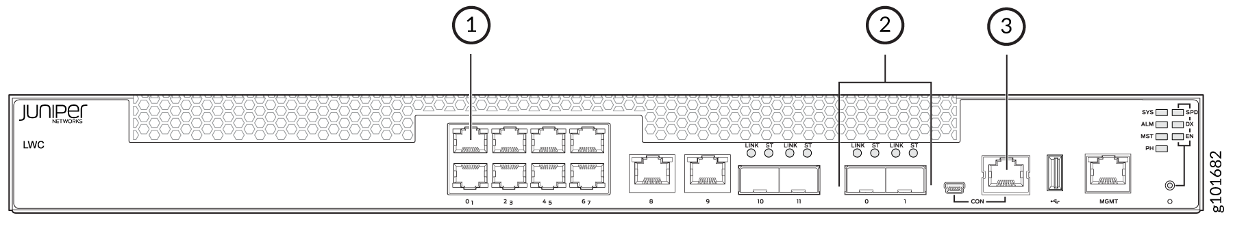
- 1GbE RJ-45 network port (only the port 0) used to access the captive portal (for configuration and diagnostics)
- 1GbE/10GbE SFP+ uplink ports (connects the LWC to the internal and external networks)
- Console port (accessible only to Juniper Networks resident engineers)
Rear Panel of an LWC Device
The rear panel of an LWC device consists grounding points, an electrostatic discharge (ESD) point, exhaust vents, a power switch, and an AC power cord inlet (see Figure 2).
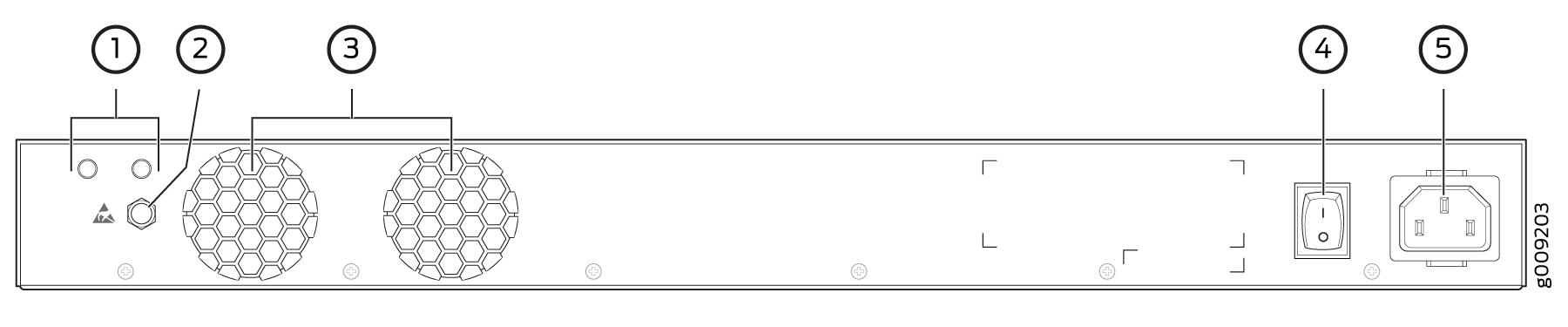
1 — Ground points | 4 — Power switch |
2 — Electrostatic discharge (ESD) point | 5 — AC power cord inlet |
3 — Exhaust vents |
Network Port and Uplink Port LEDs on an LWC Device
Each network port and uplink port on the front panel of an LWC device has two LEDs that indicate link activity and port status (see Figure 3).
Table 1 describes the link activity LED.
|
LED |
Color |
State and Description |
|---|---|---|
|
Link/Activity |
Green |
|