Installing the LTE Mini-PIM in a SRX Series Services Gateway
To install the LTE Mini-PIM in a services gateway:
You can install only one Mini-PIM in a services gateway. The Mini-PIM can be installed in any of the Mini-PIM slots on the services gateway.
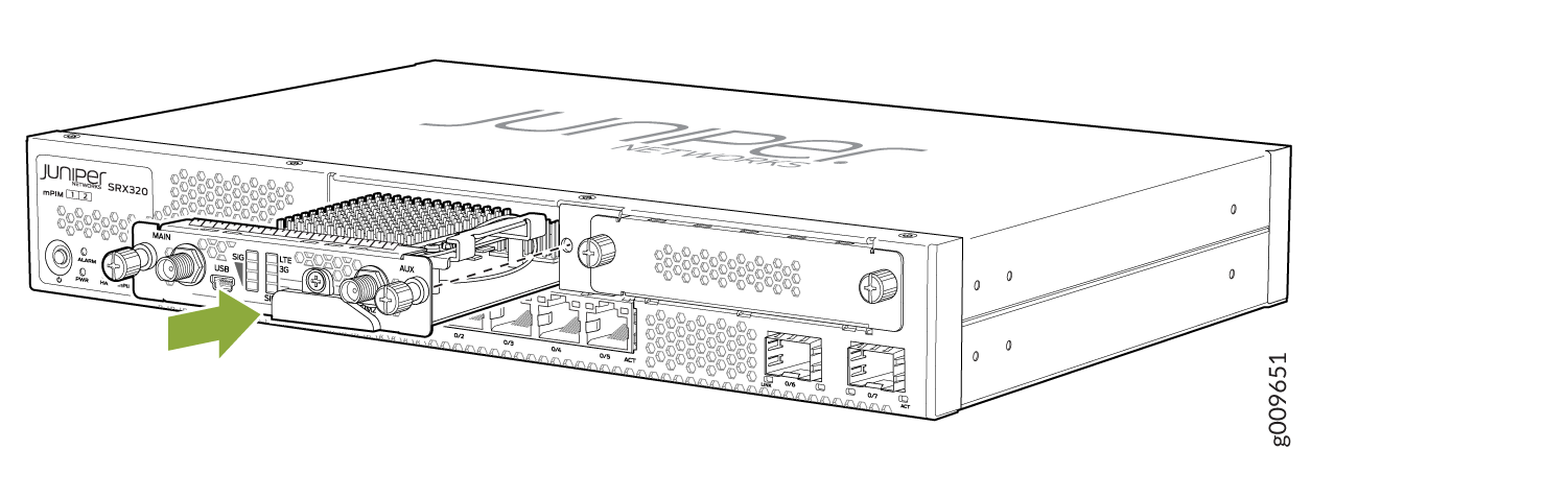
- Slide the Mini-PIM in until it lodges firmly in the services
gateway. See Figure 1.Figure 1: Installing the LTE Mini-PIM
- Remove the SIM slot cover. Insert the SIM card into the
SIM slot, SIM 1.
You can use the other slot, SIM 2, for installing a secondary or backup SIM.
Note:When you insert SIM cards into the respective slots, make sure to orient the cards correctly. Insert SIM1 into its slot with the connector side (SIM card chip) facing down and the notch on the left. Insert SIM2 into its slot with the connector side facing up and the notch on the right. See Figure 2.
Figure 2: Inserting the SIM Card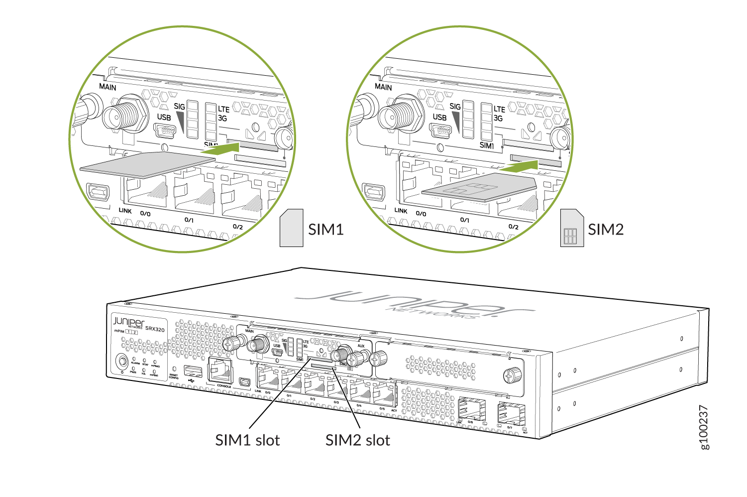
To remove a SIM card from its slot, press the edge of the card projecting out of the slot.
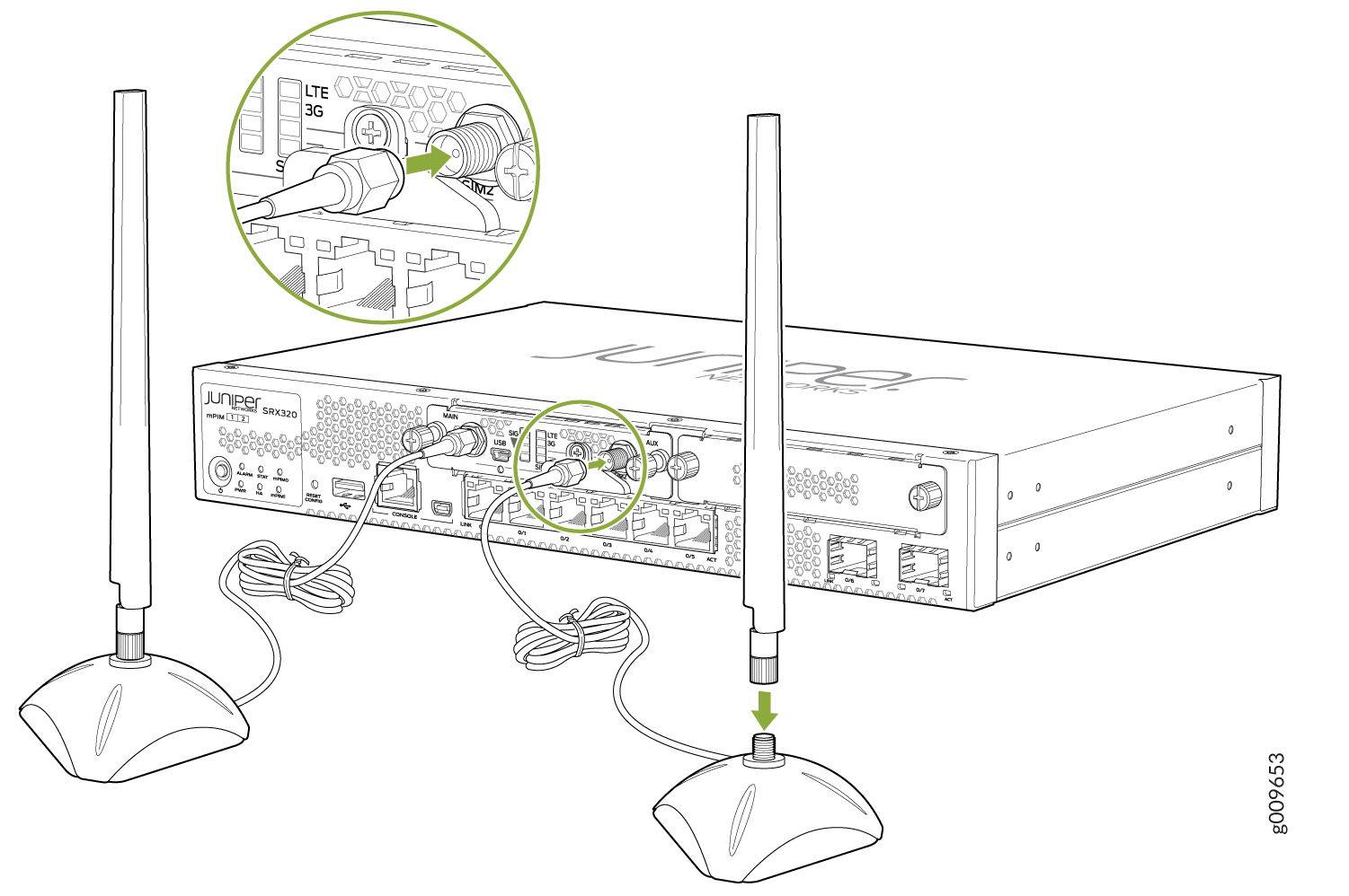
- Attach the antennas to the antenna base. Connect the cables
from each antenna base to the SMA connectors on the Mini-PIM. See Figure 3.Figure 3: Attaching the Antennas
The antenna base is magnetic and can be attached to the rack directly, if the rack is metallic. Else, you can mount the antenna base on the rack using the mounting brackets. See Figure 4.
Figure 4: Mounting the Antennas on a Rack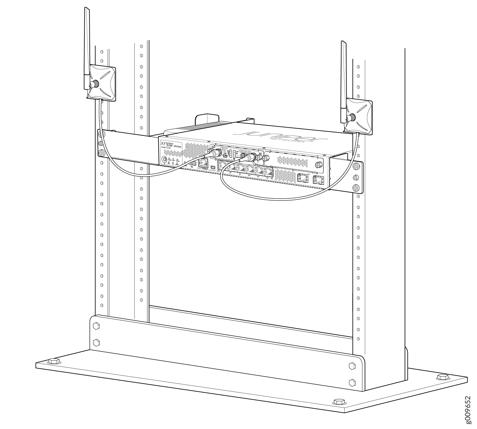 Note:
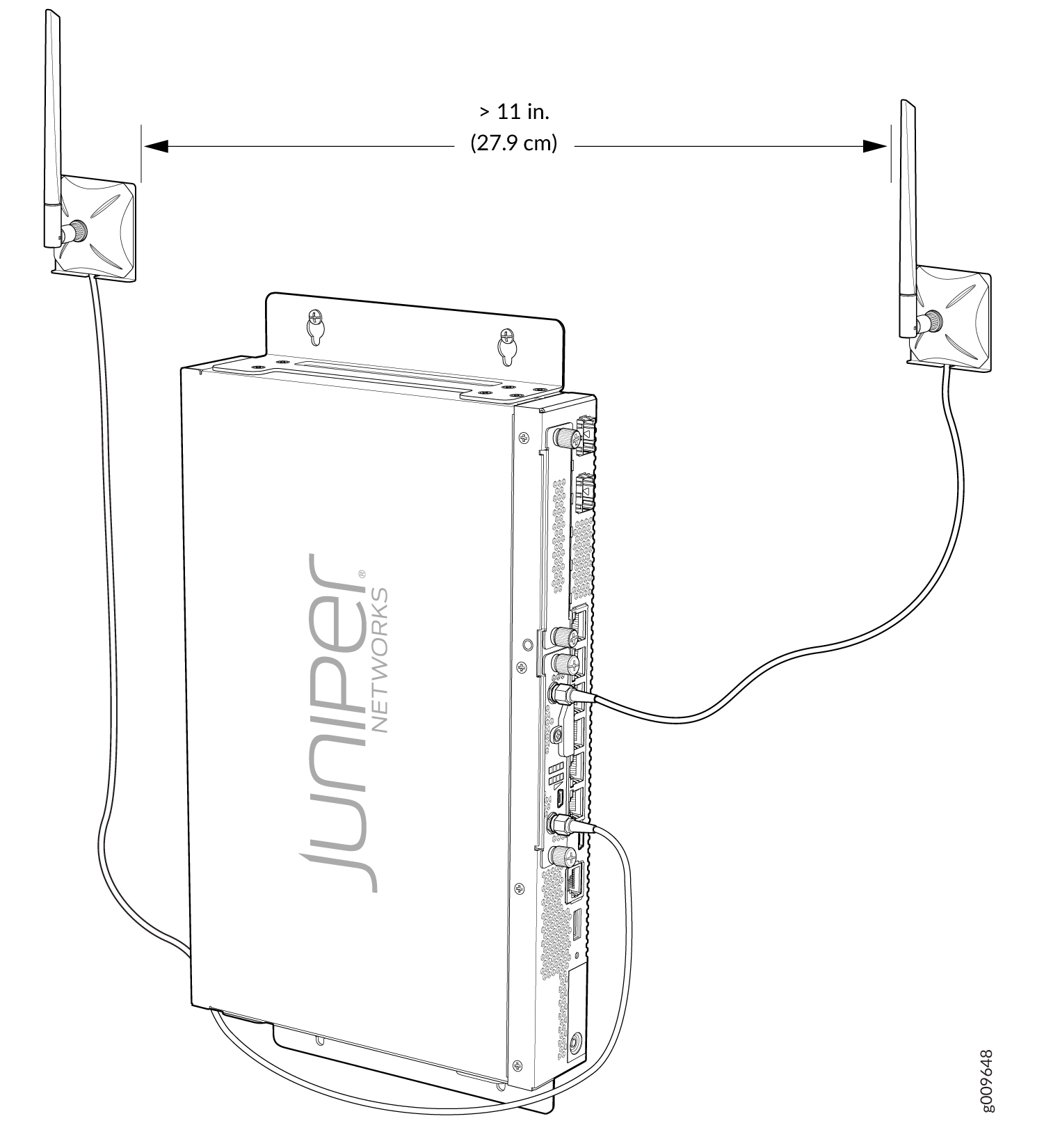
Note:For SRX320 Services Gateways, which can be mounted on a wall, the antennas can be mounted as shown in Figure 5.
Figure 5: Mounting the Antennas on a Wall