Maintaining the JRR200 Power System
Maintaining the JRR200 Route Reflector Power Supplies
Purpose
For optimum performance, verify the condition of the power supplies.
Action
On a regular basis:
To check the status of the power supplies, issue the
show chassis environment pemcommand. The output shown below is an example.user@host> show chassis environment pem PEM 0 status: State Online Airflow Front to Back Temperature OK DC Output Voltage(V) Current(A) Power(W) Load(%) 12 10 120 18 PEM 1 status: State Online Airflow Front to Back Temperature OK DC Output Voltage(V) Current(A) Power(W) Load(%) 12 10 120 18Make sure that the power and grounding cables are arranged so that they do not obstruct access to other JRR200 route reflector components.
Routinely check the status LEDs on the power supply faceplates to determine whether the power supplies are functioning normally. Each power supply faceplate displays three LEDs to indicate the status of the power supply.
Check the power LED on the front panel of the device. Power supply failure or removal triggers an alarm that causes LEDs to light. You can display the associated error messages by issuing the following command:
user@host> show chassis alarms
Periodically inspect the site to ensure that the grounding and power cables connected to the device are securely in place and that there is no moisture accumulating near the device.
Replacing the JRR200 Route Reflector AC Power Supply
Each AC power supply is a field-replaceable unit (FRU) installed in the rear panel of JRR200 route reflector. You can remove and replace the power supplies without powering off JRR200 route reflector or disrupting route reflector functions.
All the power supplies must be installed and operational for optimal functioning of JRR200 route reflector.
- Removing a JRR200 Route Reflector AC Power Supply
- Installing a JRR200 Route Reflector AC Power Supply
Removing a JRR200 Route Reflector AC Power Supply
Ensure that you have the following parts and tools available:
ESD grounding strap
Antistatic bag or an antistatic mat
Replacement power supply
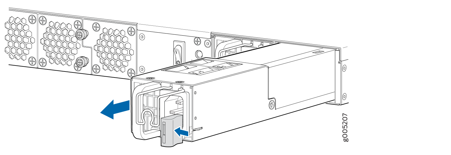
To remove a power supply from JRR200 route reflector (see Figure 1):
- Place one hand under the power supply to support it and
slide it completely out of the chassis. Take care not to touch power
supply components, pins, leads, or solder connections.Figure 1: Removing an AC Power Supply
Installing a JRR200 Route Reflector AC Power Supply
Ensure that you have the following parts and tools available:
ESD grounding strap
Do not mix AC and DC power supplies in the same chassis.
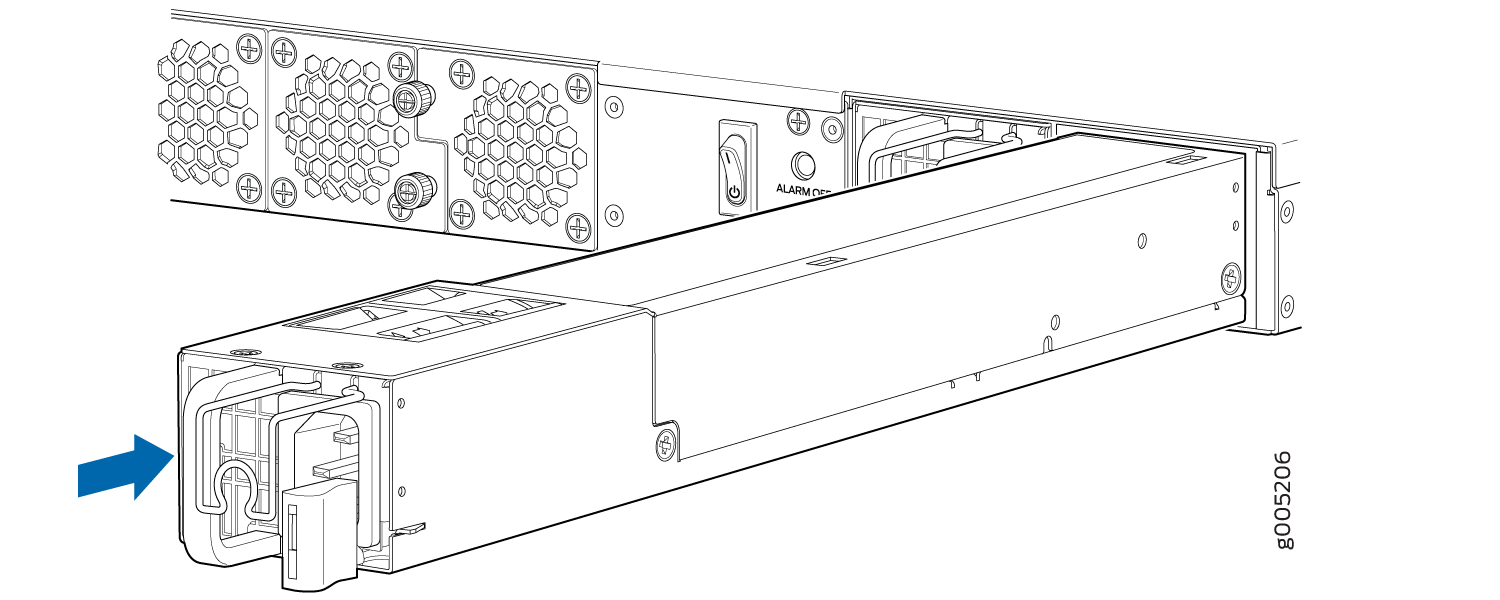
To install an AC power supply (see Figure 2):
- Using both hands, place the power supply in the power
supply slot on the rear panel of the JRR200 route reflector and slide
it in until it is fully seated and the ejector lever fits into place.
You will hear a distinct click when the power supply is fully seated
in the chassis.Figure 2: Installing an AC Power Supply
Replacing the JRR200 Route Reflector DC Power Supply
Each DC power supply is a field-replaceable unit (FRU) installed in the rear panel of the JRR200 device. You can remove and replace the power supplies without powering off the JRR200 device or disrupting route reflector functions.
All the power supplies must be installed and operational for optimal functioning of the JRR200 device.
- Removing a JRR200 Route Reflector DC Power Supply
- Installing a JRR200 Route Reflector DC Power Supply
Removing a JRR200 Route Reflector DC Power Supply
Ensure that you have the following parts and tools available:
ESD grounding strap
Phillips (+) screwdriver, number 2
Antistatic bag or an antistatic mat
Replacement power supply
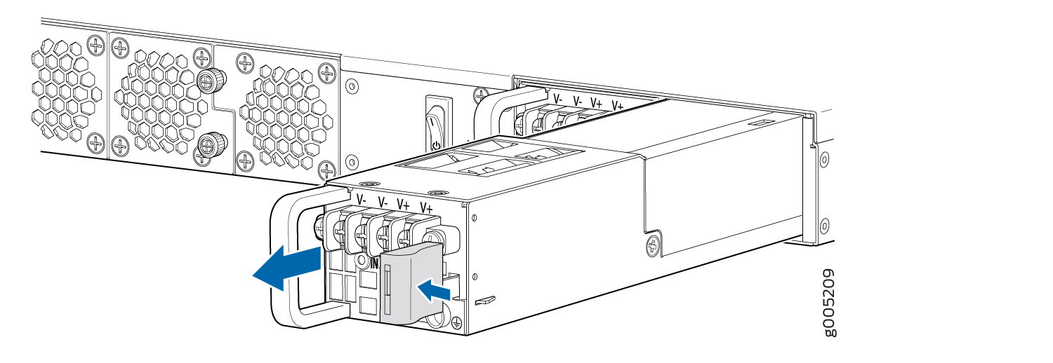
To remove a DC power supply (see Figure 3):
- Taking care not to touch power supply pins, leads, or
solder connections, place one hand under the power supply to support
it. Grasp the power supply handle with your other hand and pull the
power supply completely out of the chassis.Figure 3: Removing a DC Power Supply
Installing a JRR200 Route Reflector DC Power Supply
Ensure that you have the following parts and tools available:
ESD grounding strap
Do not mix AC and DC power supplies in the same chassis.
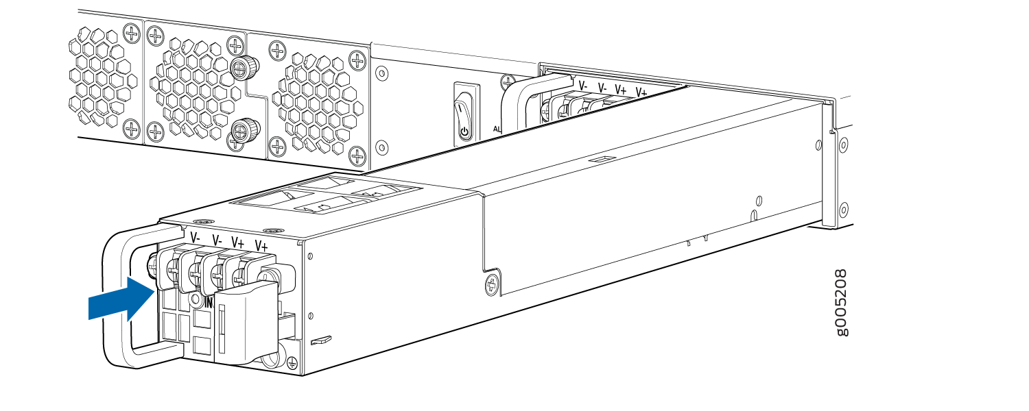
To install a DC power supply (see Figure 4):
- Using both hands, place the power supply in the power
supply slot on the rear panel of the chassis and slide it in until
it is fully seated and the ejector lever fits into place. You will
hear a distinct click when the power supply is fully seated in the
chassis.Figure 4: Installing a DC Power Supply