Maintaining the JRR200 Cooling System
Maintaining the Fan Trays on the JRR200 Route Reflector
Purpose
For optimum cooling, verify the condition of the fan trays.
Action
Monitor the status of the fan trays. All the fan trays work in unison to cool the JRR200 route reflector. If one fan trayfails, the redundant fan tray acts as a backup. A major alarm is triggered when a fan fails, and a minor alarm and major alarm is triggered when a fan tray is removed. We recommend that you replace the fan tray immediately to maintain proper cooling.
To display the status of the cooling system, issue the
show chassis environmentcommand. The output shown below is an example.user@host> show chassis environment Class Item Status Measurement Temp CBD 0 System Temp1 - Front OK 34 degrees C / 93 degrees F CBD 0 System Temp2 - Back OK 37 degrees C / 98 degrees F CBD 0 CPU0 Temp OK 52 degrees C / 125 degrees F CBD 0 CPU1 Temp OK 43 degrees C / 109 degrees F Power Power Supply 0 OK Power Supply 1 OK Fans Fan Tray 0 Fan 0 OK Spinning at normal speed Fan Tray 0 Fan 1 OK Fan Tray 1 Fan 0 OK Spinning at normal speed Fan Tray 1 Fan 1 OK Fan Tray 2 Fan 0 OK Spinning at normal speed Fan Tray 2 Fan 1 OK Fan Tray 3 Fan 0 OK Spinning at normal speed Fan Tray 3 Fan 1 OK
Replacing the JRR200 Route Reflector Fan Tray
Each fan tray is a field-replaceable unit (FRU) installed in the rear panel of JRR200 route reflector. You can remove and replace the fan trays without powering off JRR200 route reflector or disrupting route reflector functions.
All the fan trays must be installed and operational for optimal functioning of JRR200 route reflector.
To replace the fan tray:
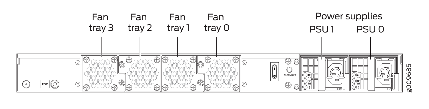
- Identify the physical location of the faulty fan tray
on the rear panel of the chassis. Figure 1 shows how the fan trays are numbered.Figure 1: JRR200 Route Reflector Fan Tray Numbering