Connecting the JRR200 to Power
Connect the Grounding Cable
Ensure that you have the following parts and tools available:
Electrostatic discharge (ESD) grounding wrist strap
Phillips (+) screwdriver, number 2
16 AWG single-strand wire grounding cable (green and yellow wire)
Grounding lug (ring-type, vinyl-insulated TV14-6R lug, or equivalent)
One metric M5 x 10 mm grounding screw
To meet safety and electromagnetic interference (EMI) requirements and to ensure proper operation, the JRR200 Route Reflector must be adequately grounded before power is connected. You must provide a grounding lug to connect the route reflector to earth ground.
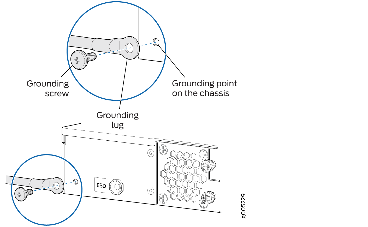
You ground the route reflector by connecting a grounding cable to earth ground and then attaching it to the chassis grounding point located on the back panel of the device using an M5 x 10 mm grounding screw.
Before you connect power to the route reflector, a licensed electrician must attach a cable lug to the grounding cable that you supply. A cable with an incorrectly attached lug can damage the route reflector (for example, by causing a short circuit).
To connect the route reflector to earth ground:
- Place the grounding cable lug over the grounding point
on the rear of the chassis.
 Note:
Note:The JRR200 route reflector should be permanently connected to ground during normal operation. A licensed electrician must attach a cable lug to the grounding cable. A cable with an incorrectly attached lug can damage the JRR200 route reflector.
When removing the chassis, turn off the power, and disconnect the grounding cable.
Connecting Power to an AC-Powered JRR200 Route Reflector
Ensure that you have a power cord appropriate for your geographical location available to connect AC power to the JRR200 Route Reflector. Before you begin connecting AC power:
Ensure that you have taken the necessary precautions to prevent electrostatic discharge (ESD) damage.
Ensure that you have connected the device chassis to earth ground.
CAUTION:Before you connect power to the JRR200 route reflector, a licensed electrician must attach a cable lug to the grounding cable that you supply. A cable with an incorrectly attached lug can damage the device (for example, by causing a short circuit).
To meet safety and electromagnetic interference (EMI) requirements and to ensure proper operation, you must properly ground the JRR200 route reflector chassis before connecting power.
Check that the power supplies are fully inserted into the chassis.
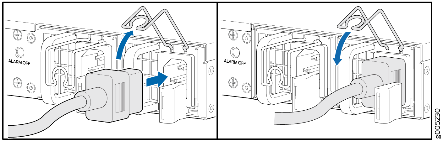
To connect AC power:
- Insert the coupler end
of the power cord into the AC power cord inlet on the AC power supply
faceplate. Push the power cord retainer onto the power cord.Note:
An AC-powered device gets additional grounding when you connect the power supply in the device to a grounded AC power outlet by using the power cord.
Connecting Power to a DC-Powered JRR200 Route Reflector
Before you begin connecting DC power to a JRR200 Route Reflector:
Ensure that you have taken the necessary precautions to prevent electrostatic discharge (ESD) damage.
Ensure that you have connected the chassis to earth ground.
CAUTION:Before you connect power to the JRR200 route reflector, a licensed electrician must attach a cable lug to the grounding cable that you supply. A cable with an incorrectly attached lug can damage the device (for example, by causing a short circuit).
To meet safety and electromagnetic interference (EMI) requirements and to ensure proper operation, you must properly ground the JRR200 route reflector chassis before connecting power.
Check that the power supplies are fully inserted into the chassis.
Ensure that you have the following parts and tools available:
DC power source cables (14–16 AWG) with ring lug
Phillips (+) screwdriver, number 2
Multimeter
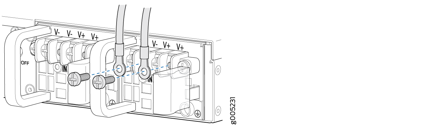
To connect DC power:
Before performing the following procedure, ensure that there is no power in the DC circuit. To ensure that all power is cut off, locate the circuit breaker on the panel board that services the DC circuit, switch the circuit breaker to the off (0) position, and tape the switch handle of the circuit breaker in the off position.
- Tighten the screws on the power supply terminals until
snug using the screwdriver. Do not overtighten.