JRR200 Chassis
JRR200 Route Reflector Chassis Front Panel
Figure 1 shows the front panel of the JRR200 route reflector.
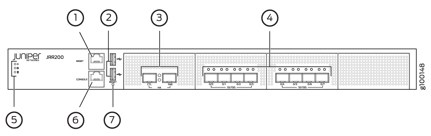
Table 1 lists the components on the front panel of the JRR200 route reflector.
|
Number |
Component |
Description |
|---|---|---|
|
1 |
Management port |
Gigabit Ethernet port to connect to the device over the network. |
|
2 |
USB ports |
Two USB 2.0 ports that accept a USB storage device. |
|
3 |
HA ports |
The two HA ports are not supported on the JRR200 route reflector. |
|
4 |
SFP+ ports |
Eight 1-Gigabit Ethernet/10-Gigabit Ethernet SFP+ ports for network traffic. |
|
5 |
LEDs |
Indicate component and system status at a glance. |
|
6 |
Console port |
Connects a laptop to the JRR200 route reflector for CLI management. The port uses an RJ-45 serial connection, is configured as DTE, and supports the RS-232 (EIA-232) standard. |
|
7 |
RESET button |
Returns the JRR200 route reflector to the factory-default configuration. |
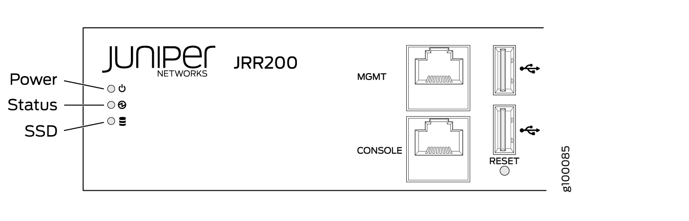
JRR200 Route Reflector Chassis Status LEDs
Figure 2 shows the chassis status LEDs that are located on the front panel of the JRR200 route reflector. Table 2 describes the LEDs.
|
LED |
Description |
|---|---|
|
Power |
|
|
Status |
|
|
SSD |
|
Management Port LEDs
The management port has two LEDs that indicate link activity and status of the management port.
Table 3 describes the LEDs.
|
LED |
Description |
|---|---|
|
Link/Activity (LED on the left) |
|
|
Speed (LED on the right) |
|
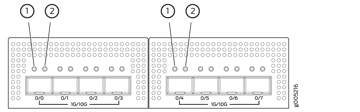
Network Port LEDs
Each SFP+ port has two status LEDs located above the port. Table 4 describes the LEDs. Figure 3 shows the LEDs.
|
Callout |
LED |
Description |
|---|---|---|
|
1 |
Link (LED on the left) |
|
|
2 |
Speed/Activity (LED on the right) |
|
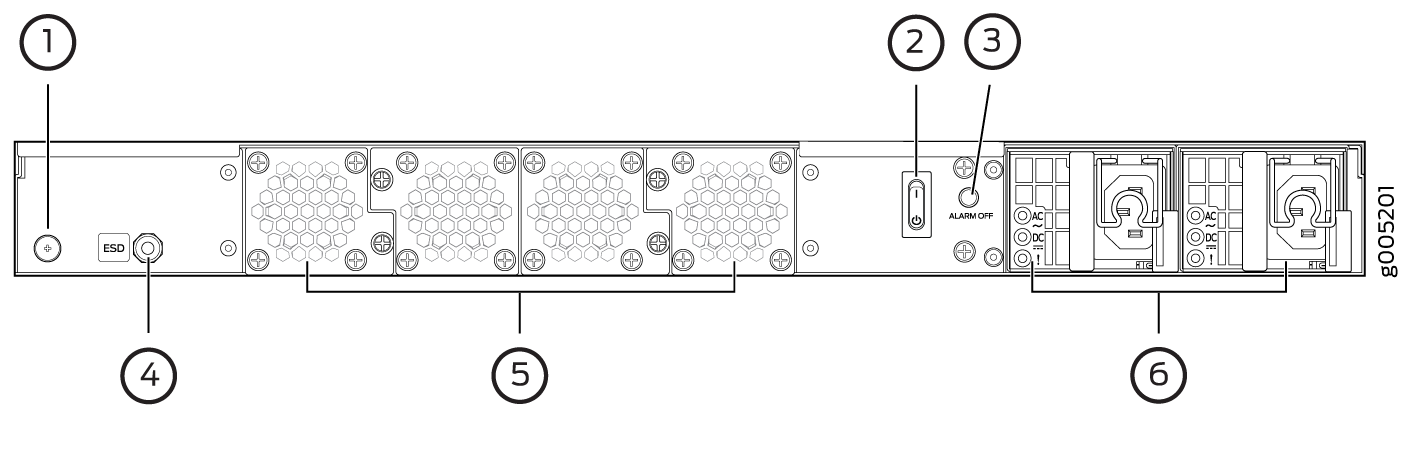
JRR200 Route Reflector Chassis Rear Panel
Figure 4 shows the rear panel of the JRR200 Route Reflector. Table 5 lists and describes the rear panel components.
|
Number |
Component |
Description |
|---|---|---|
|
1 |
Grounding point |
Connects the JRR200 route reflector chassis to earth ground. |
|
2 |
Power switch |
Use the Power switch to power on or power off the JRR200 route reflector. |
|
3 |
Alarm Off button |
Use this button to turn off an alarm triggered because of an abnormal DC output voltage caused by any of the following:
|
|
4 |
ESD point |
For personal safety, while working on the JRR200 route reflector, use the ESD outlet to plug in an ESD grounding strap to prevent your body from sending static charges to the route reflector. |
|
5 |
Fan trays |
Four fan trays for cooling the JRR200 route reflector and its components. Each fan tray contains two fans. Three fan trays are required for proper air flow across the chassis internal components. The fourth fan tray provides redundancy. |
|
6 |
Power supply |
Two power supply slots. Each power supply contains a power cord outlet. Two 650-W DC or AC power supplies are provided with the JRR200 route reflector. |
JRR200 Route Reflector Physical Specifications
The JRR200 Route Reflector chassis is a rigid sheet metal structure that houses all the components. Table 6 lists the physical specifications of the chassis.
|
Description |
Value |
|---|---|
|
Chassis height |
1.75 in. (4.45 cm) |
|
Chassis width |
17.48 in. (44.40 cm) |
|
Chassis depth |
25 in. (63.50 cm) |
|
Weight |
|
You can mount the JRR200 route reflector on a standard 19-in. four-post rack or in a standard 19-in. enclosed cabinet.