Maintaining the EX9200 Line Cards
Handling and Storing Line Cards
Components in the line cards are fragile. To avoid damaging the line cards, follow the procedures in this topic. The procedures use the following terms to describe the four edges of the line cards:
Faceplate—Edge of the line card that has connectors into which you insert the transceivers.
Connector edge—Edge opposite the faceplate.
Top edge—Edge at the top of the line card when the line card is vertical.
Bottom edge—Edge at the bottom of the line card when the line card is vertical.
Failure to handle line cards as specified in these procedures can cause irreparable damage to them.
Holding a Line Card
You must hold a line card horizontally when installing it in the chassis. You may hold a line card vertically or horizontally when carrying it.
Be prepared to support the full weight as you slide the line card into the chassis.
To hold a line card vertically:
- Orient the line card so that the faceplate faces you. To verify the orientation, confirm that the text on the line card is right-side up.
- Place one hand around the line card faceplate about a quarter of the way down from the top edge. Do not press hard on it.
- Place the other hand at the bottom edge of the line card.
If the line card is horizontal before you grasp it, place your left hand around the faceplate and your right hand along the bottom edge.
To hold a line card horizontally:
Orient the line card so that the faceplate faces you.
Grasp the top edge with your left hand and the bottom edge with your right hand.
You can rest the faceplate of the line card against your body as you carry it.
Take care not to hit the line card against any object as you carry it. Line card components are fragile.
Never hold or grasp the line card anywhere except the places mentioned in these procedures. In particular, never grasp the connector edge. See Figure 1.
Never carry the line card while holding the faceplate with only one hand.
Do not rest any edge of a line card directly against a hard surface. See Figure 2.
If you must rest a line card temporarily on an edge, place a cushion between the edge and the surface.
Do not stack line cards on top of one another or on top of any other component. Place each line card separately in an antistatic bag or on an antistatic mat placed on a flat, stable surface.
Storing a Line Card
You must store a line card in the chassis or in a spare shipping container, horizontally and sheet metal side down. Do not stack line cards on top of one another or on top of any other component. Place each line card separately in an antistatic bag or on an antistatic mat placed on a flat, stable surface.
Because a line card is heavy, and because antistatic bags are fragile, inserting the line card into the bag is best done with two people, each to do one of the following steps.
To insert a line card into an antistatic bag:
- Hold the line card in the horizontal position with the faceplate facing you.
- Slide the opening of the bag over the line card connector edge.
If you must insert the line card into a bag by yourself:
Lay the line card horizontally on a flat, stable surface, sheet metal side down.
Orient the line card with the faceplate facing you.
Carefully insert the line card connector edge into the opening of the bag and pull the bag toward you to cover the line card.
Maintaining Line Card Cables
Components in the line cards are fragile. To extend the lives of your line card cables and to avoid problems that can result from cable damage, follow these procedures:
To maintain line card cables:
Place excess cable out of the way. Do not allow fastened loops of cable to dangle from the connector. Placing fasteners on the loops helps retain their shape.
Keep the cable connections clean and free of dust and other particles, which can cause drops in the received power level. Always inspect cables and clean them if necessary before connecting a port.
Label both ends of line card cables to identify them.
Unpacking a Line Card Used in an EX9200 Switch
Before you unpack a line card:
Ensure that you have taken the necessary precautions to prevent electrostatic discharge (ESD) damage (see Prevention of Electrostatic Discharge Damage).
Ensure that you know how to handle and store the line card (see Handling and Storing Line Cards).
The line cards for EX9200 switches are rigid sheet-metal structures that house the line card components including network ports. The line cards are shipped in a cardboard carton, secured with foam packing material.
The line cards are maximally protected inside the shipping carton. Do not unpack the line cards until you are ready to install them in the switch chassis.
To unpack a line card (see Figure 3):
- Move the shipping carton to a staging area as close to the installation site as possible.
- Position the carton so that the arrows are pointing up.
- Open the top flaps on the shipping carton.
- Pull out the packing material, which holds the line card in place.
- Remove the line card from the antistatic bag.
- Save the shipping carton and packing materials in case you need to move or ship the line card later.
Removing a Line Card from an EX9200 Switch
Before you begin removing a line card from an EX9200 switch:
Ensure that you have taken the necessary precautions to prevent electrostatic discharge (ESD) damage. See Prevention of Electrostatic Discharge Damage.
If there are any transceivers installed in the line card, remove them before you remove the line card. See Remove a Transceiver.
Ensure that you know how to handle and store the line card. See Handling and Storing Line Cards.
Ensure that you have the following parts and tools available to remove a line card from an EX9200 switch chassis:
ESD grounding strap
An antistatic bag or an antistatic mat
Replacement line card or a cover panel and its captive screws to cover the empty slot
EX9200 switches have field-replaceable unit (FRU) line cards that can be installed in the line card slots on the front of the switch chassis. The line cards are hot-insertable and hot-removable: You can remove and replace them without powering off the switch or disrupting switch functions. However, we recommend that you take them offline before removing them.
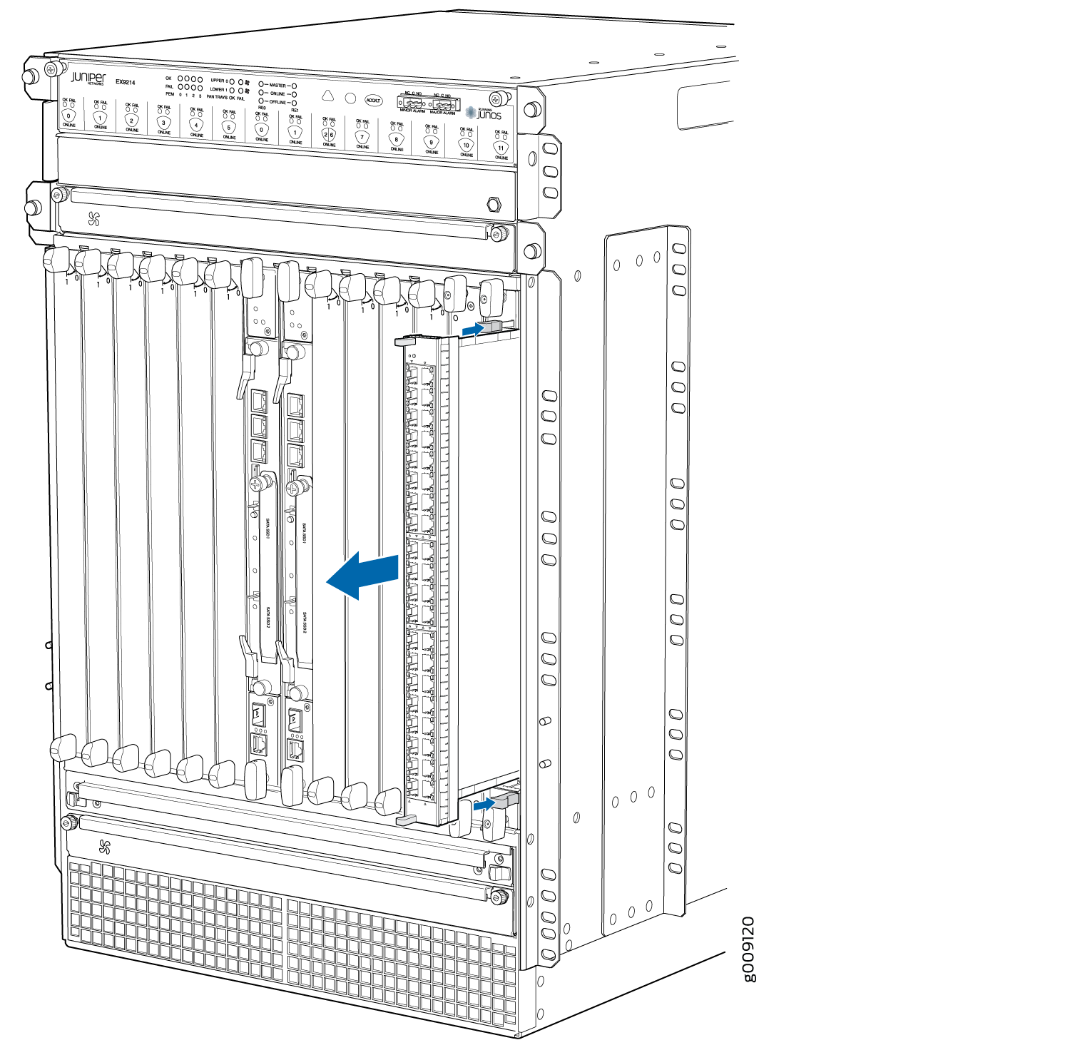
To remove a line card from an EX9200 switch:
Figure 4 shows removing a line card from an EX9204 switch. The procedure and orientation of the line card are the same for EX9208. The procedure is the same for EX9214 switch; however, the orientation of the line cards is different—it is installed vertically into the top and bottom of the chassis.
Installing a Line Card in an EX9200 Switch
Before you begin installing a line card in the switch:
Ensure that you have taken the necessary precautions to prevent electrostatic discharge (ESD) damage (see Prevention of Electrostatic Discharge Damage).
If there are any transceivers installed in the line card, remove them before you install the line card. For instructions on removing transceivers, see Remove a Transceiver.
Ensure that you know how to handle and store the line card (see Handling and Storing Line Cards).
Ensure that you have the following parts and tools available to install a line card in the switch:
ESD grounding strap
EX9200 switches have field-replaceable unit (FRU) line cards that can be installed in the line card slots on the front of the switch chassis. The line cards are hot-insertable and hot-removable: You can remove and replace them without powering off the switch or disrupting switch functions. However, we recommend that you take them offline before removing them.
To install a line card in the switch:
On EX9204, EX9208, and EX9214 switches, when a line card is brought online, if the aggregate interface is initialized before the child interface is marked as part of the aggregate interface, there might be a loss of traffic from the aggregate interface for up to 30 seconds and the CPU usage of the line card installed on the switch might go up to 100%.
Figure 5 shows installing a line card in an EX9204 switch. The procedure and orientation of the line card are the same for EX9208. The procedure is the same for EX9214 switch; however, the orientation of the line card is different—it is installed vertically in the chassis.
You can verify that the line card is functioning correctly by
issuing the show chassis fpc and show chassis fpc
pic-status commands.
If you have a Juniper J-Care service contract, register any addition, change, or upgrade of hardware components at https://www.juniper.net/customers/support/tools/updateinstallbase/ . Failure to do so can result in significant delays if you need replacement parts. This note does not apply if you replace existing components with the same type of component.
Removing a MIC from an EX9200-MPC Line Card
Before you begin removing a MIC from an EX9200-MPC line card:
Ensure that you have taken the necessary precautions to prevent electrostatic discharge (ESD) damage (see Prevention of Electrostatic Discharge Damage).
Ensure that you know how to handle and store the line card (see Handling and Storing Line Cards).
Ensure that you have the following parts and tools available:
(If you will replace the MIC by installing only one EX9200-10XS-MIC or EX9200-20F-M-MIC) A septum if it is not installed in the line card and screws to secure the septum
One or two MIC slot cover panels and screws for installing the MIC slot cover panels. You must install both the MIC slot cover panels if you will not install any MIC, or install one cover panel in the empty portion of the MIC slot if you will install only one EX9200-10XS-MIC or EX9200-20F-M-MIC.
Rubber safety caps to cover transceivers
ESD grounding strap
Phillips (+) screwdriver, number 2
The EX9200-MPC line card has two slots on the faceplate in which you can install the supported Modular Interface Cards (MICs). The EX9200-MPC line card accepts the following MICs:
EX9200-10XS-MIC
EX9200-20F-MIC
EX9200-40T-MIC
The MICs are hot-insertable and hot-removable field replaceable units (FRUs): You can remove and replace them without powering off the switch or disrupting switch functions. However, if you remove a MIC, the interface for that MIC ceases to function.
Do not remove any MIC from the EX9200-40F line card, EX9200-40F-M line card, EX9200-40T line card, or EX9200-4QS line card.
To remove a MIC from an EX9200-MPC line card:
Installing a MIC in an EX9200-MPC Line Card
Before you begin installing a MIC in an EX9200-MPC line card:
Ensure that you have taken the necessary precautions to prevent electrostatic discharge (ESD) damage (see Prevention of Electrostatic Discharge Damage).
Ensure that you know how to handle and store the line card (see Handling and Storing Line Cards).
Ensure that you have the following parts and tools available:
(If you will install only one EX9200-10XS-MIC or EX9200-20F-MIC) A septum and screws to secure the septum
(If you will install only one EX9200-10XS-MIC or EX9200-20F-MIC) A cover panel and screws to secure the cover panel
Rubber safety caps to cover transceivers
ESD grounding strap
Phillips (+) screwdriver, number 2
The EX9200-MPC line card accepts any of the following Modular Interface Cards (MICs):
EX9200-10XS-MIC
EX9200-20F-MIC
EX9200-40T-MIC
The EX9200-MPC line card has two slots on the faceplate in which you can install the MICs. You can install the MICs in the following configurations:
One EX9200-10XS-MIC
One EX9200-20F-MIC
One EX9200-10XS-MIC and one EX9200-20F-MIC
Two EX9200-10XS-MICs
Two EX9200-20F-MICs
One EX9200-40T-MIC
The MICs are hot-insertable and hot-removable field replaceable units (FRUs): You can remove and replace them without powering off the switch or disrupting switch functions. However, if you remove a MIC, the interface for that MIC stops functioning.
To install a MIC in an EX9200-MPC line card:
- If you will install only one EX9200-10XS-MIC or EX9200-20F-MIC
and if there is no septum installed in the line card, install the
septum (see Figure 8):
- Insert a screw each into the holes labeled S on the bottom surface of the line card and tighten the screws by
using the screwdriver.Figure 8: Installing the Septum
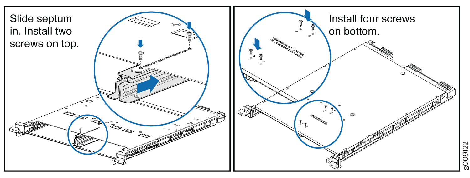
- Insert a screw each into the holes labeled S on the bottom surface of the line card and tighten the screws by
using the screwdriver.
- If you are installing an EX9200-40T-MIC and if there is
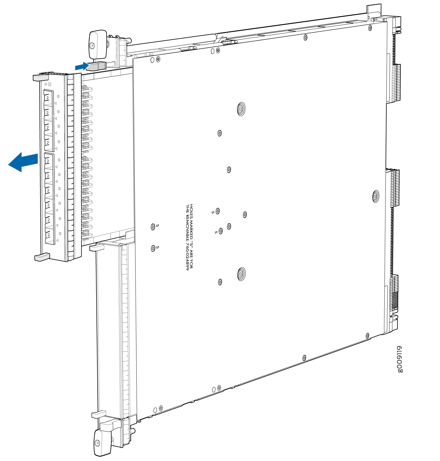
a septum installed in the line card, remove the septum (see Figure 9):
- Remove the screws labeled S on the bottom surface of the line card.
- Remove the two screws labeled S on the top surface of the line card.
- Slide the septum out of the line card.
- Save the septum and screws for later use.
Figure 9: Removing the Septum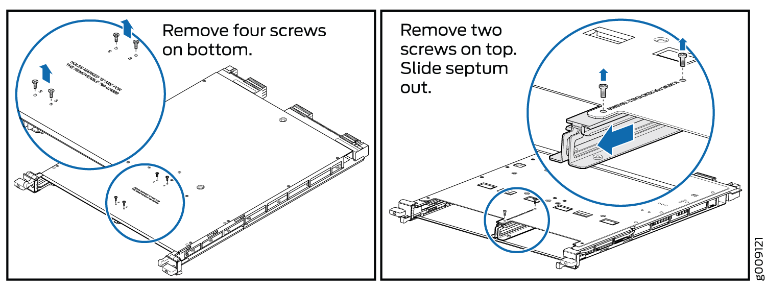 Warning:
Do not look directly into a fiber-optic transceiver or into the ends of fiber-optic cables. Fiber-optic transceivers and fiber-optic cable connected to a transceiver emit laser light that can damage your eyes.
CAUTION:Do not leave a fiber-optic transceiver uncovered, except when you are inserting or removing cable. The safety cap keeps the port clean and protects your eyes from accidental exposure to laser light.
- Bring the MIC online by pressing the power button on the
MIC until the OK/FAIL LED on the MIC is lit green.
You can also bring the MIC online by issuing the following CLI command:
user@host> request chassis mic fpc-slot slot-number mic-slot slot-number online
Figure 10: Installing an EX9200-10XS-MIC or EX9200-20F-MIC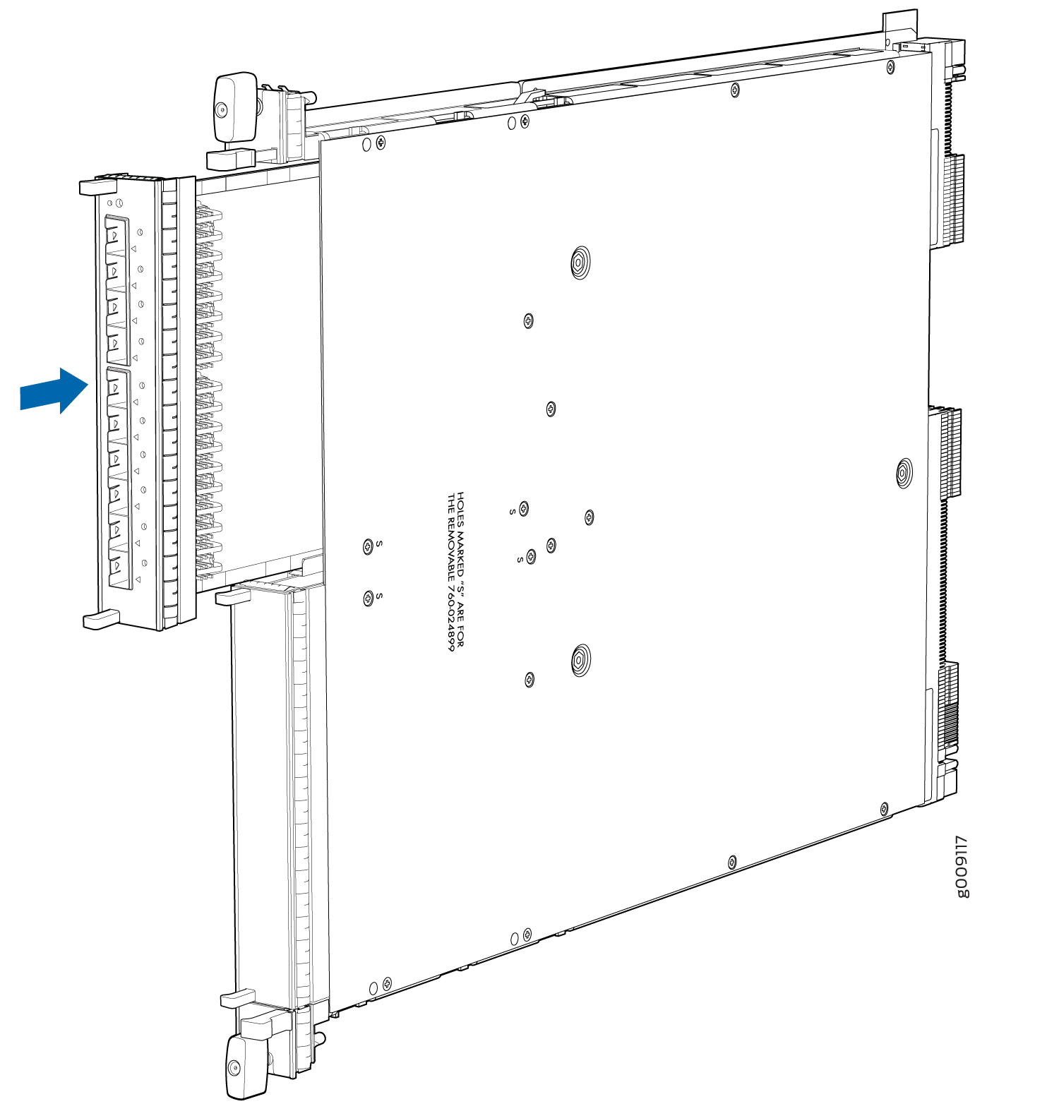 Figure 11: Installing an EX9200-40T-MIC