Maintaining the EX4650 Cooling System
Removing a Fan Module from an EX4650 Switch
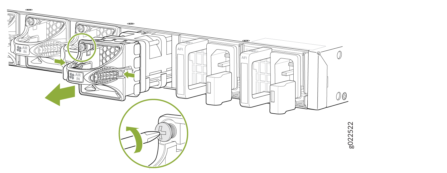
Ensure that you have the following parts and tools available:
-
Phillips (+) screwdriver, number 2
-
An antistatic bag or an antistatic mat
-
A replacement fan module
The fan module in EX4650 switches is a hot-removable and hot-insertable field-replaceable unit (FRU) installed in the rear panel of the switch: You can remove and replace it without powering off the switch or disrupting switch functions.
The fan module slots are at the left side of the rear panel.Figure 1 shows how to remove a fan module.
Both the fan modules must be installed and operational for optimal functioning of the switch.
Installing a Fan Module in an EX4650 Switch
Before you install a fan module in the switch:
-
Ensure you understand how to prevent electrostatic discharge (ESD) damage. See Prevention of Electrostatic Discharge Damage.
Ensure that you have the following parts and tools available to install a fan module in the switch chassis:
-
ESD grounding strap
-
Phillips (+) screwdriver, number 2 (not provided)
EX4650 is shipped with redundant fans (4+1). Each fan module is a hot-removable and hot-insertable field-replaceable unit (FRU) installed in the rear panel of the switch. You can remove and replace it without powering off the switch or disrupting switch functions.
Do not mix:
-
Fan modules with different airflow labels (AIR IN (AFI) and AIR OUT (AFO)) in the same chassis.
-
Power supplies with different airflow labels (AIR IN (AFI) and AIR OUT (AFO)) in the same chassis.
-
Power supplies and fan modules with different airflow labels (AIR IN (AFI) and AIR OUT (AFO)) in the same chassis.
-
AC and DC power supplies in the same chassis.
The fan module slots are located between the management ports and power supply units.
If you have a Juniper J-Care service contract, register any addition, change, or upgrade of hardware components at https://www.juniper.net/customers/support/tools/updateinstallbase/. Failure to do so could result in significant delays if you need replacement parts. This note does not apply if you replace existing components with the same type of component.
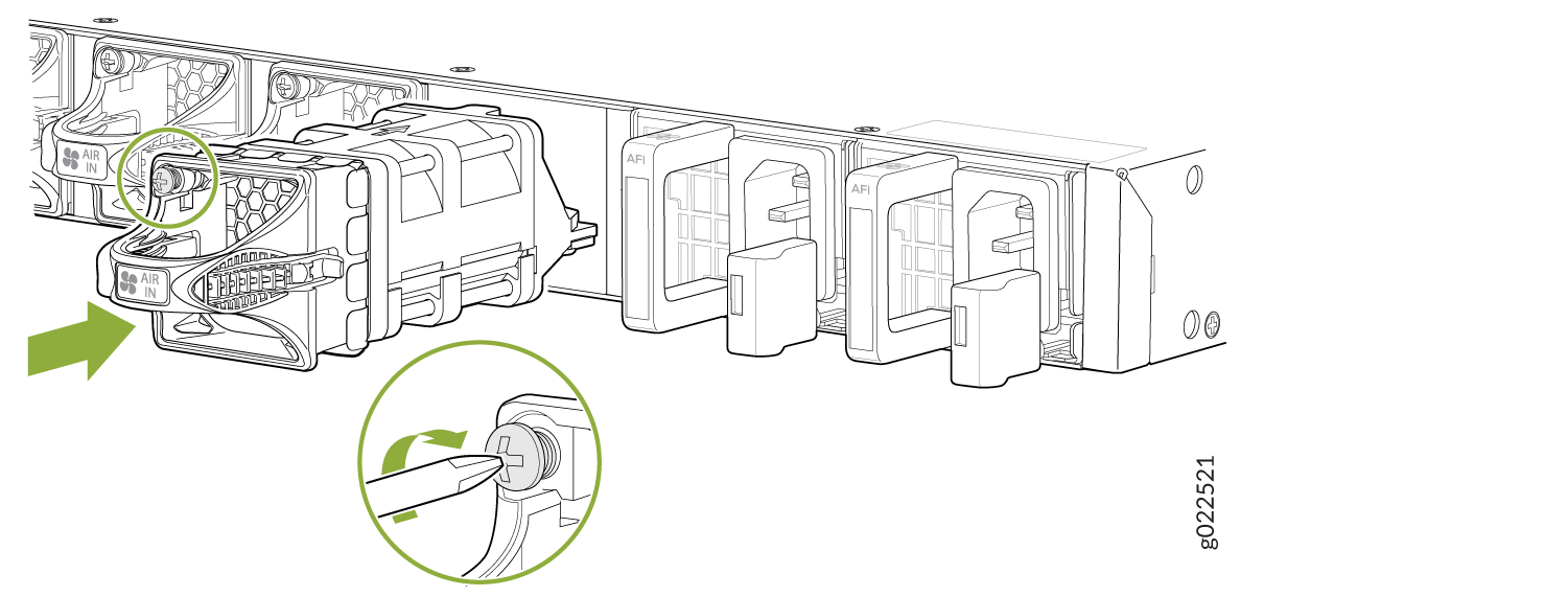
- Ensure that you have the correct fan module. The label AFI or AFO on the fan module must match the label AFI or AFO on the installed power supply.
- Attach the ESD grounding strap to your bare wrist, and connect the strap to the ESD point on the chassis.
- Remove the fan module from its bag.
- Hold the handle of the fan module with one hand and support the weight of the module with the other hand. Place the fan module in the fan module slot on the rear panel of the switch and slide it in until it is fully seated and latched.
- Tighten the captive screws on the faceplate of the fan module by using the screwdriver. The recommended torque value is 4.34 in-lb (0.49 Nm).