EX4650 Chassis
Chassis Status LEDs on EX4650 Switches
EX4650 switches have four chassis status LEDs (labeled ALM, SYS, MST, and ID) (see Figure 1).
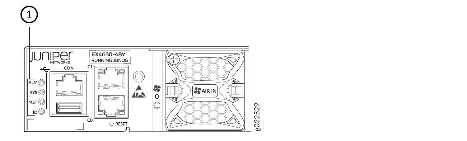
1 — Chassis status LEDs |
Table 1 describes
the chassis status LEDs on an EX4650 switch, their colors and states,
and the status they indicate. You can view the colors of the three
LEDs remotely through the CLI by issuing the operational mode command show chassis led.
|
LED Label |
Color |
State and Description |
|---|---|---|
|
ALM (Alarm) |
Unlit |
There is no alarm or the switch is halted. |
|
Red |
There is a major alarm. Note:
A major hardware fault has occurred, such as a temperature alarm or power failure, and the switch has halted. Power off the unit by setting the AC power source outlet to the OFF (O) position, or unplugging the AC power cords. Correct any voltage or site temperature issues, and allow the switch to cool down. Power on the unit switch and monitor the power supply and fan LEDs to help determine where the error is occurring. s the network link and turns off the ALM LED..) |
|
|
Amber |
There is a minor alarm. Note:
The Alarm (ALM) LED glows yellow
if you commit a configuration to make it active on the switch and
do not also create a rescue configuration to back it up. To save the
most recently committed configuration as the rescue configuration,
enter the operational mode command |
|
|
SYS (System) |
Unlit |
The switch is powered off or halted. |
|
Green(On steadily) |
Junos OS for EFX Series is loaded on the switch. |
|
|
Green (Blinking) |
The switch is participating as a member of a Virtual Chassis. |
|
|
MST (Primary) |
Green(On steadily) |
Indicates a standalone EX4650 switch. |
|
ID(Identification) |
Unlit |
The beacon feature is not enabled on the switch. This feature is enabled using the request chassis beacon command. Blinking—The beacon feature is enabled. |
|
Blinking |
The beacon feature is enabled on the switch. This feature is enabled using the request chassis beacon command |
A major alarm (red) indicates a critical error condition that requires immediate action.
A minor alarm (yellow) indicates a noncritical condition that requires monitoring or maintenance. A minor alarm that is left unchecked might cause interruption in service or performance degradation.
All three LEDs can be lit simultaneously.
Management Port LEDs on EX4650 Switches
The two management ports on the rear panel of an EX4650 switch have two LEDs that indicate Link/Activity and status of the management port.Figure 2 shows the location of the management port.
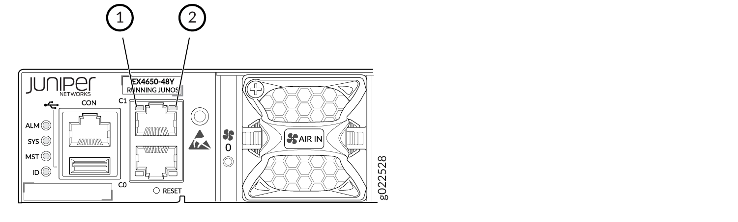
1 — Status LED | 2 — Link/Activity LED |
Table 2 describes the Link/Activity LED.
|
LED |
Color |
State and Description |
|---|---|---|
|
Link/Activity |
Green |
|
|
Status |
Green/Amber |
Indicates the speed.
|
Access Port and Uplink Port LEDs on EX4650 Switches
Each network port and SFP+ uplink port has two LEDs that show the link activity and status of the port. The built-in QSFP+ port on a EX4650 switch has one LED that shows both the link activity and status of the port.
The following figures in this topic shows the location of those LEDs:
Figure 3 shows the location of the LEDs on the QSFP uplink ports.
Figure 4 shows the location of the LEDs on the SFP network ports.
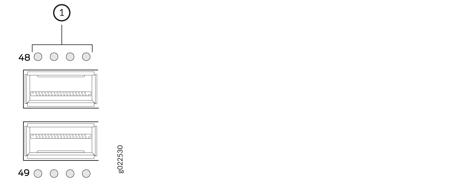
1 — Network Port LEDs. |
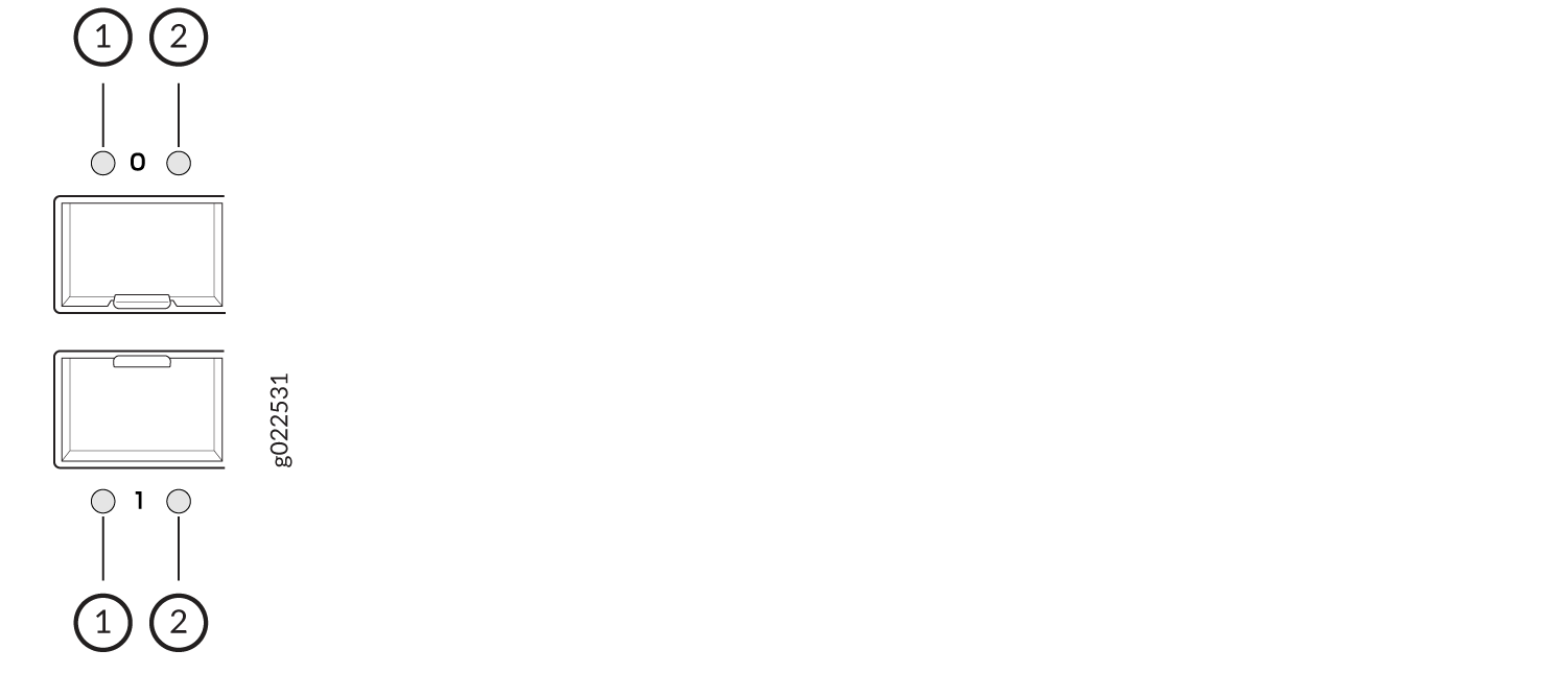
1 — Link/Activity LED | 2 — Status LED |
The Table 3 describes the link activity LED on network ports, SFP+ uplink ports, and built-in QSFP+ ports.
LED |
Color |
State and Description |
|---|---|---|
Link activity |
Green |
|
Table 4 describes the Status LED on SFP+ uplink ports.
LED |
LCD Indicator |
State and Description |
|---|---|---|
Status |
Green |
Indicates the speed. The speed indicators are:
|
Table 5 describes the Status LED on QSFP+ ports in EX4650 switches.
LED |
LCD Indicator |
State and Description |
|---|---|---|
Status |
Green |
Indicates the status. The status indicators are:
|