Maintain Transceivers
Remove a Transceiver
Before you remove a transceiver from a device, ensure that you have taken the necessary precautions for the safe handling of lasers (see Laser and LED Safety Guidelines and Warnings).
Ensure that you have the following parts and tools available:
An antistatic bag or an antistatic mat
Rubber safety caps to cover the transceiver and fiber-optic cable connector
A dust cover to cover the port or a replacement transceiver
The transceivers for Juniper Networks devices are hot-removable and hot-insertable field-replaceable units (FRUs): You can remove and replace them without powering off the device or disrupting device functions.
After you remove a transceiver or when you change the media-type configuration, wait for 6 seconds for the interface to display the operational commands.
Figure 1 shows how to remove a QSFP+ transceiver. The procedure is the same for all types of transceivers except the QSFP28 and CFP transceivers.
To remove a transceiver from a device:
- To remove an SFP, SFP+, XFP, or a QSFP+ transceiver:
- Grasp the transceiver ejector lever and gently slide the
transceiver approximately 0.5 in. (1.3 cm) straight out
of the port.CAUTION:
To prevent ESD damage to the transceiver, do not touch the connector pins at the end of the transceiver.
Figure 1: Remove a QSFP+ Transceiver 1—Ejector lever
To remove a CFP transceiver:
- Grasp the transceiver ejector lever and gently slide the
transceiver approximately 0.5 in. (1.3 cm) straight out
of the port.
Remove a QSFP28 Transceiver
Before you remove a transceiver from a device, ensure that you have taken the necessary precautions for safe handling of lasers (see Laser and LED Safety Guidelines and Warnings).
Ensure that you have the following parts and tools available:
An antistatic bag or an antistatic mat
Rubber safety caps to cover the transceiver and fiber-optic cable connector
A dust cover to cover the port or a replacement transceiver
The transceivers for Juniper Networks devices are hot-removable and hot-insertable field-replaceable units (FRUs). You can remove and replace them without powering off the device or disrupting the device functions.
After you insert a transceiver or after you change the media-type configuration, wait for 6 seconds for the interface to display operational commands.
We recommend that you use only optical transceivers and optical connectors purchased from Juniper Networks with your Juniper Networks device.
To remove a QSFP28 transceiver (see Figure 2):
- If there is a cable management system, arrange the cable
in the cable management system to prevent it from dislodging or developing
stress points. Secure the cable so that it does not support its own
weight as it hangs to the floor. Place excess cable out of the way
in a neatly coiled loop in the cable management system. Placing fasteners
on the loop helps to maintain its shape.CAUTION:
Do not bend the fiber-optic cable beyond its minimum bend radius. An arc smaller than a few inches in diameter can damage the cable and cause problems that are difficult to diagnose.
Figure 2: Remove a QSFP28 Transceiver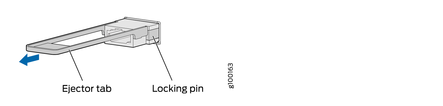
Install a Transceiver
Before you install a transceiver in a device, ensure that you have taken the necessary precautions for safe handling of lasers (see Laser and LED Safety Guidelines and Warnings).
Ensure that you have a rubber safety cap available to cover the transceiver.
The transceivers for Juniper Networks devices are hot-removable and hot-insertable field-replaceable units (FRUs): You can remove and replace them without powering off the device or disrupting the device functions.
After you insert a transceiver or after you change the media-type configuration, wait for 6 seconds for the interface to display operational commands.
We recommend that you use only optical transceivers and optical connectors purchased from Juniper Networks with your Juniper Networks device.
If you face a problem running a Juniper Networks device that uses a third-party optic or cable, the Juniper Networks Technical Assistance Center (JTAC) can help you diagnose the source of the problem. Your JTAC engineer might recommend that you check the third-party optic or cable and potentially replace it with an equivalent Juniper Networks optic or cable that is qualified for the device.
Figure 3 shows how to install a QSFP+ transceiver. The procedure is the same for all types of transceivers except the QSFP28 and CFP transceivers.
To install a transceiver:
To prevent electrostatic discharge (ESD) damage to the transceiver, do not touch the connector pins at the end of the transceiver.
1 — Ejector lever |
Install a QSFP28 Transceiver
Before you install a transceiver in a device, ensure that you have taken the necessary precautions for safe handling of lasers (see Laser and LED Safety Guidelines and Warnings).
Ensure that you have a rubber safety cap available to cover the transceiver.
The transceivers for Juniper Networks devices are hot-removable and hot-insertable field-replaceable units (FRUs): You can remove and replace them without powering off the device or disrupting the device functions.
After you insert a transceiver or after you change the media-type configuration, wait for 6 seconds for the interface to display operational commands.
We recommend that you use only optical transceivers and optical connectors purchased from Juniper Networks with your Juniper Networks device.
If you face a problem running a Juniper Networks device that uses a third-party optic or cable, the Juniper Networks Technical Assistance Center (JTAC) can help you diagnose the source of the problem. Your JTAC engineer might recommend that you check the third-party optic or cable and potentially replace it with an equivalent Juniper Networks optic or cable that is qualified for the device.
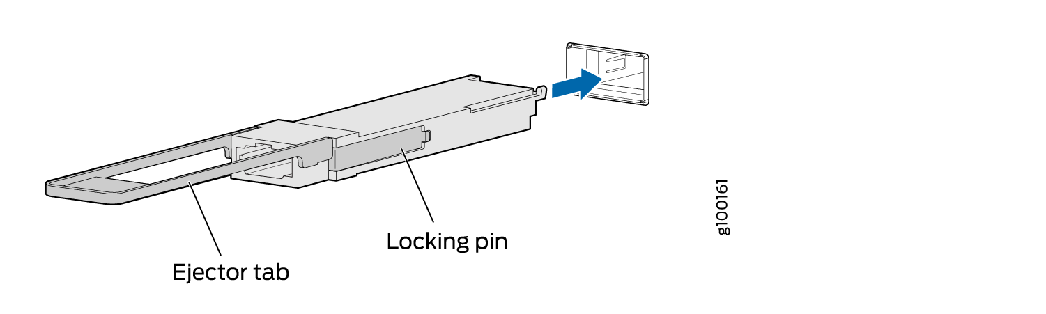
To install a QSFP28 transceiver (see Figure 4):
- Orient the transceiver in front of the port so that the
QSFP28 connector faces the appropriate direction.Figure 4: Install a QSFP28 Transceiver