Connect the EX4100-H to Power
Connect Earth Ground to an EX4100-H Switch
To ensure proper operation and to meet safety and electromagnetic interference (EMI) requirements, you must connect the EX4100-H switch models to earth ground before you connect power to the switch. You must use the protective earthing terminal on the switch chassis to connect the switch to earth ground.
You must always ground the 340 W external PSU as well. It is recommended that you ground the EX4100-H-12MP switch and the external PSU.
You must install the EX4100-H switches in a restricted-access location and ensure that the switch chassis is always properly grounded. EX4100-H switches have a two-hole protective grounding terminal on the front panel of the switch chassis. Under all circumstances, use this grounding connection to ground the switch chassis. For AC-powered switches, you must also use the grounding wire in the AC power cord along with the two-hole grounding lug connection. This tested switch meets or exceeds all applicable EMC regulatory requirements with the two-hole protective grounding terminal.
Ensure that a licensed electrician has attached the appropriate grounding lug to the grounding cable that you supply. Using a grounding cable with an incorrectly attached lug can damage the switch.
The surface of the EX4100-H-12MP will be warm as this is a fanless unit and
is based on ambient temperature. Issue show chassis
environment to check if there are temperature-related
alarms.
Before you connect earth ground to an EX4100-H switch, ensure that you have parts and tools listed in Table 1 available:
| Item | Switch Models/PSUs | Description |
|---|---|---|
| Earthing terminal location |
EX4100-H-12MP EX4100-H-24MP EX4100-H-48MP |
Front panel of the switch Rear panel of the switch Rear panel of the switch |
|
Earthing terminal location |
340 W external PSU for the EX4100-H-12MP |
Front panel of the PSU |
| Grounding cable requirements | EX4100-H | 6 AWG (13.3 mm²), minimum 90° C wire,
or as permitted by the local code—not provided
|
| Grounding lug specifications | EX4100-H |
Panduit LCD6-14A-L or equivalent—not provided |
| Screws to secure the grounding lug | EX4100-H | Two M5 X 10 mm stainless steel screws with washer—separately orderable |
| Tools required | EX4100-H |
A Number 2 Phillips (+) screwdriver—not provided Electrostatic discharge (ESD) grounding strap—not provided |
The grounding kit (JNP-GL-2H6-M5-RA) includes the lug and screws and is separately orderable.
To ground the EX4100-H switch to a proper ground reference:
-
Place the grounding lug attached to the grounding cable over the protective
earthing terminal on the front panel of the switch.
Figure 1: Connect the Grounding Cable to the EX4100-H-12MP Switch
 Figure 2: Connect the Grounding Cable to the EX4100-H-24MP Switch
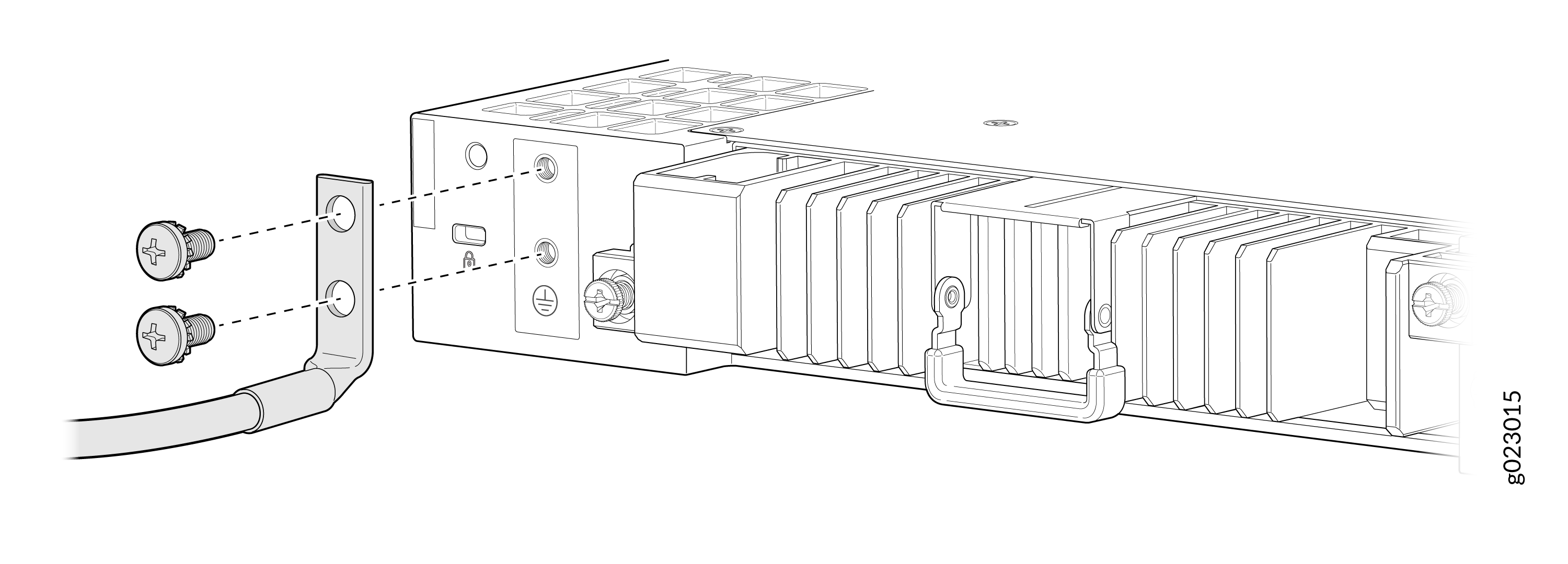 Figure 3: Connect the Grounding Cable to the EX4100-H-24F Switch
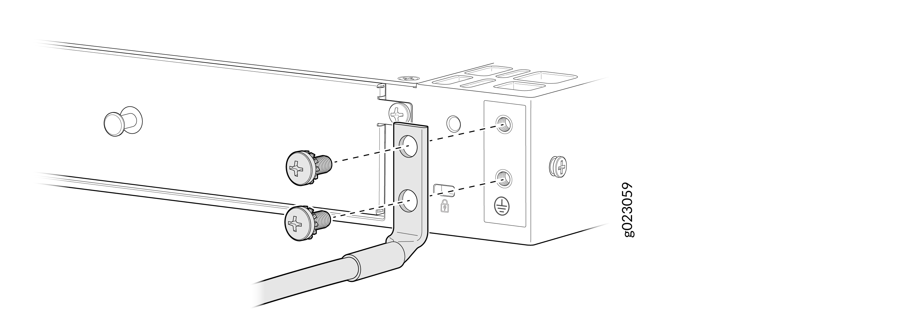
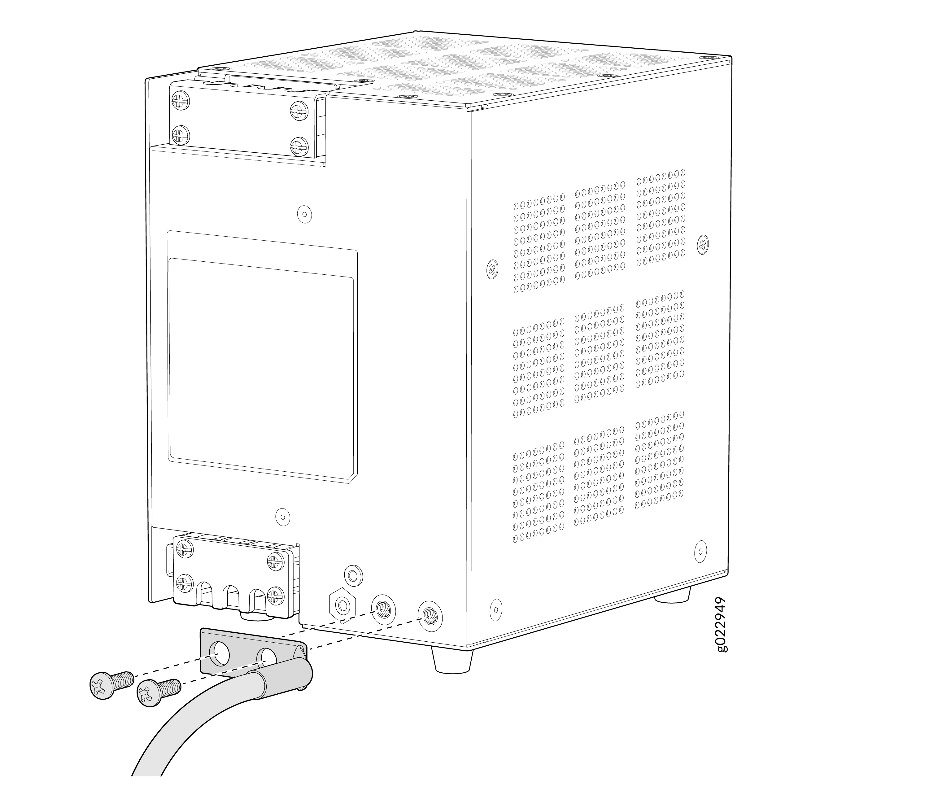
-
Place the grounding lug attached to the grounding cable over the protective
earthing terminal on the front panel of the PSU.
Figure 4: Ground the External PSU of the EX4100-H-12MP Switch
Connect Power to an EX4100-H-12MP Switch
Before you connect power to the switch, ensure that you have the following parts and tools available:
-
A power cord appropriate for your geographical location
Ensure that you have connected the switch chassis to earth ground. The power cords also provide additional grounding when you connect the power supply in the switch to a grounded power outlet by using the power cord appropriate for your geographical location (see Table 9 and Table 15).
For installations that require a separate grounding conductor to the switch chassis, ensure you have a licensed electrician complete this connection before you connect the switch to power. For instructions on connecting earth ground, see Figure 1.
The power source must be switched off before starting this procedure and switched on only after completing this procedure.
PSU output connections to the switch and PSU inlet connections should not be done when the AC/DC power cord is connected to the main source.
Connect the AC PSM to AC mains through a 2-hole circuit breaker rated at 16 A or as per local code.
To avoid the switch restart at 100% voltage dip, use of two PSU configuration is recommended for power utilities/substation deployments.
To connect power to the switch:
-
Remove the protective terminal cover from the input power terminal of the
PSU.
Note:
An initial batch of PSUs were shipped with torx screws (hexagonal shaped screws) for the protective terminal covers (input and output) of the PSU. If using a PSU with this type of screw; to install or remove the protective terminal covers from the PSU you use screwdriver type Torx 10 with torque 3.5 lb.in
Figure 5: Remove the protective terminal cover from the input power terminal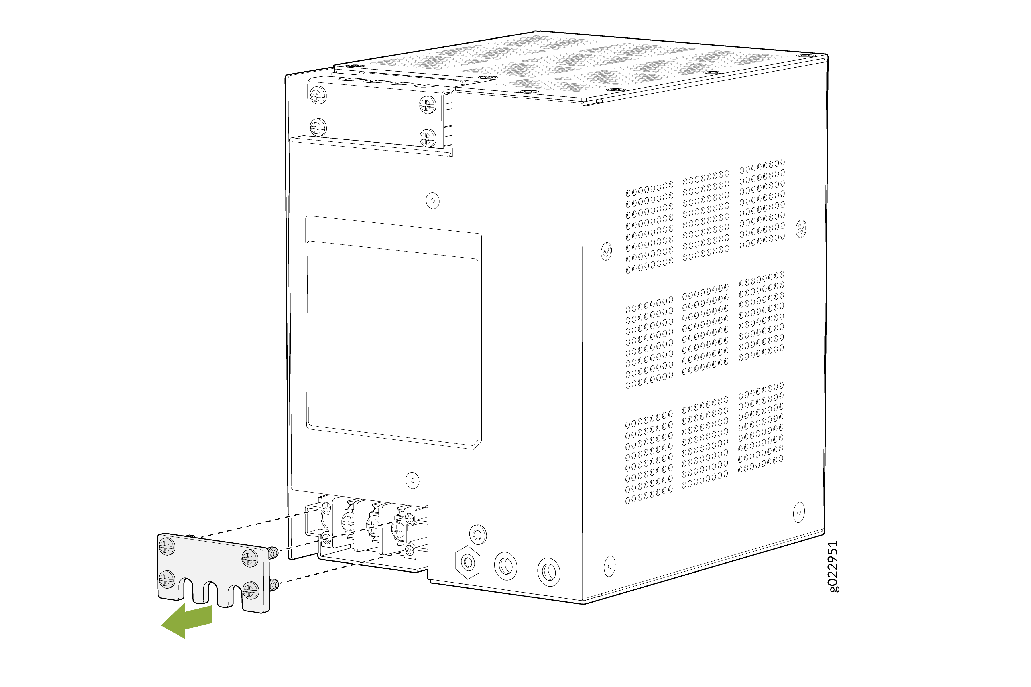
-
Insert the power cord wires of the power source into the power terminal
inputs of the PSU. On an AC PSU input, the power terminals are marked as L,
N, PE (grounding symbol). On a DC PSU input, the power terminals are marked
as +, -, and PE (grounding symbol). Always insert the grounding wire or
protective earth (PE) power cord wire into the PE input power terminal
first. For an AC PSU, insert the line, single phase (L) power cord wire and
neutral (N) power cord wire into the L and N input power terminals
respectively. For a DC PSU, insert + power cord wire and - power cord wire
into the + and - input power terminals respectively.
Note: Use Phillips #2 screwdriver with torque 6 lb.inFigure 6: Insert the power cord wires into the power terminal inputs
-
Secure the protective terminal cover with the screws over the PSU input
power terminal.
Figure 7: Secure the protective terminal cover over the input power terminal
-
Remove or loosen the protective terminal cover of the PSU output power
terminal. It is not required to remove the protective terminal cover; you
can loosen the protective terminal cover until you can see the PSU output
power terminals.
Figure 8: Remove or loosen the protective terminal cover of the PSU output power terminal
-
You connect the other ends of the interconnecting wire to the PSU connector
by initially partially loosening the screws on the sides of the PSU
connector using slotted/flat head 2.5mm screwdriver with torque 1.77 lb.in..
Then insert the other ends of the interconnecting wire into the PSU
connector slots before fastening the screws of the sides of the PSU
connector to secure the interconnecting wire to the PSU connector and
complete the PSU to switch connection. See Figure 9.
Note: To remove or install the PSU connector you use slotted/flat head 3.5mm screwdriver with torque 2.65 lb.in.
The other ends of the interconnecting wire to the PSU connector has to be connected in this manner:
Assuming you are using only one PSU:
-
Connect the interconnecting wire connected to the 54v+ PSU output terminal to the 54v+ PSU connector input of PSU 0 or PSU 1.
-
Connect the interconnecting wire connected to the 54v- PSU output terminal to the 54v- PSU connector input of PSU 0 or PSU 1.
-
Connect the interconnecting wire connected to the 12v+ PSU output terminal to the 12v+ PSU connector input of PSU 0 or PSU 1.
-
Connect the interconnecting wire connected to the 12v- PSU output terminal to the 12v- PSU connector input of PSU 0 or PSU 1.
Figure 9: Connect Switch to the PSU Using the Interconnecting Wire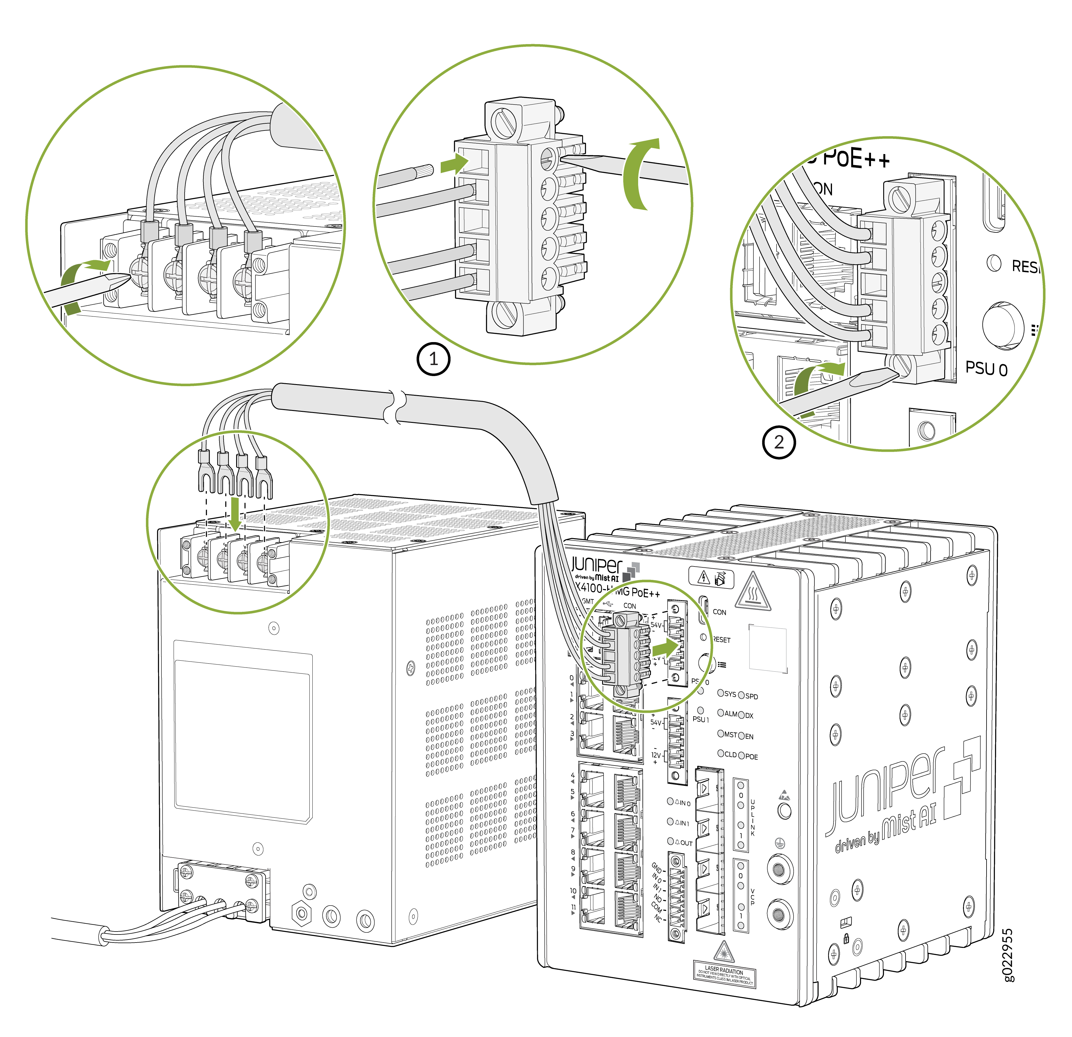
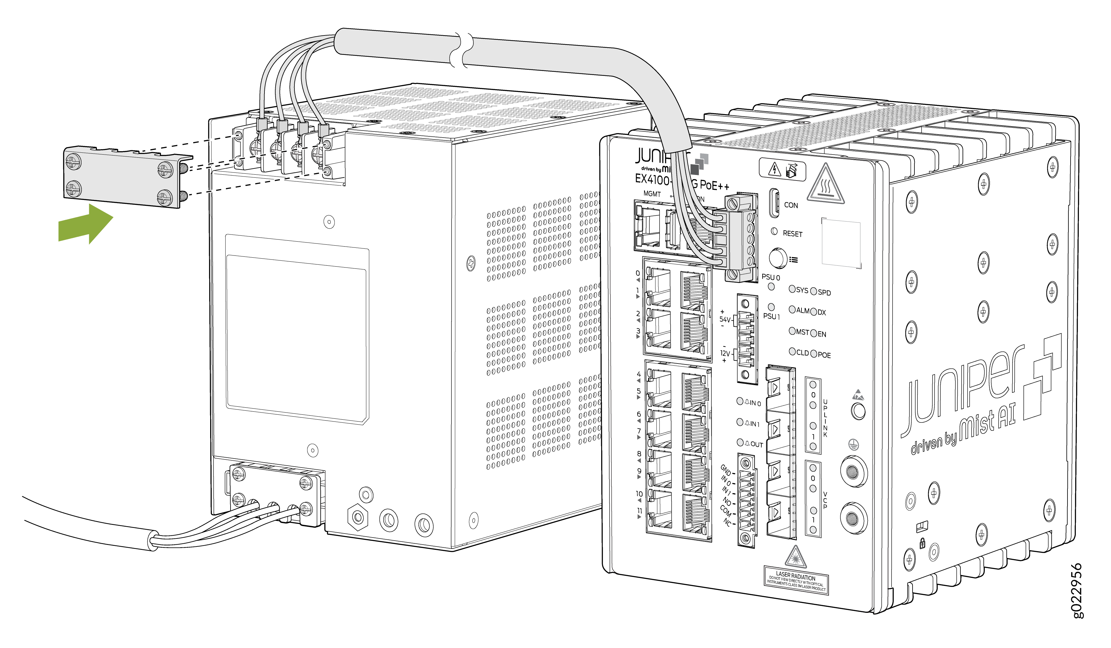
-
-
Secure the protective terminal cover with the screws over the PSU output
power terminal.
Figure 10: Secure the protective terminal cover with the screws over the output power terminal of the PSU
Connect Power to an EX4100-H-24MP or EX4100-H-24F Switch
Before you connect power, ensure that you have a power cord appropriate for your geographical location.
For information about the supported AC power cord specifications, see Table 9.
Ensure that you have connected the switch chassis to earth ground. The AC power cords also provide additional grounding when you connect the power supply in the switch to a grounded AC power outlet by using the AC power cord appropriate for your geographical location.
To ensure proper operation and to meet safety and electromagnetic interference (EMI) requirements, you must connect the EX4100-H switch to earth ground before you connect power to the switch.
EX4100-H switches have a two-hole protective grounding terminal. We recommend that you use the switch chassis protective grounding terminal as the only method for grounding the switch chassis regardless of the power supply configuration. However, if additional grounding methods are available, you can also use those methods additionally. For example, the grounding connection of the AC or DC power cord provides additional grounding. This switch was tested to meet or exceed all applicable EMC regulatory requirements with the switch chassis protective grounding terminal connected correctly.
-
For installations that require a separate grounding conductor to the switch chassis, have a licensed electrician complete this connection before you connect the switch to power. For instructions on connecting earth ground.
-
The power source must be switched off before doing this procedure, and switched on only after completing this procedure.
-
PSU output connections to switch and PSU inlet connections should not be done when the AC/DC power cord is connected to the main source.
-
When connecting the EX4100-H-24MP or EX4100-H-24F switch to the AC power source, you must provide an external circuit breaker (2-pole circuit breaker or 4-pole circuit breaker based on your switch) rated minimum 20 A in the building installation.
-
When connecting the EX4100-H-24MP or EX4100-H-24F switch to the DC power source, we recommend that you use a customer-site 2-pole circuit breaker rated for 25A 80 VDC, or as required by local electrical code.
-
To avoid the switch restart at 100% voltage dip, use of two PSU configuration is recommended for power utilities/substation deploymentsI
To connect power to the switch:
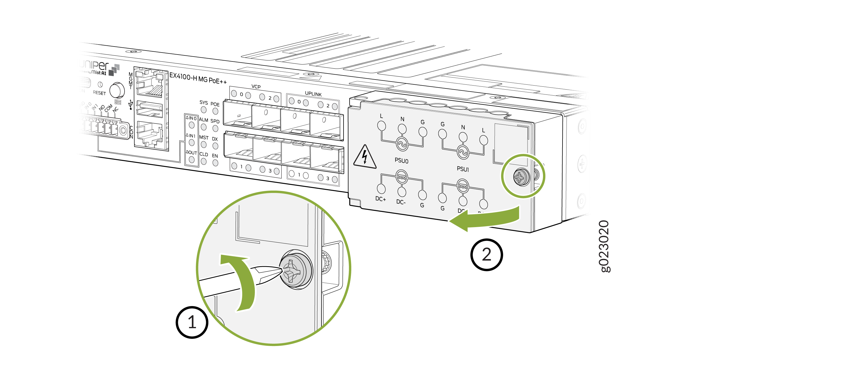
-
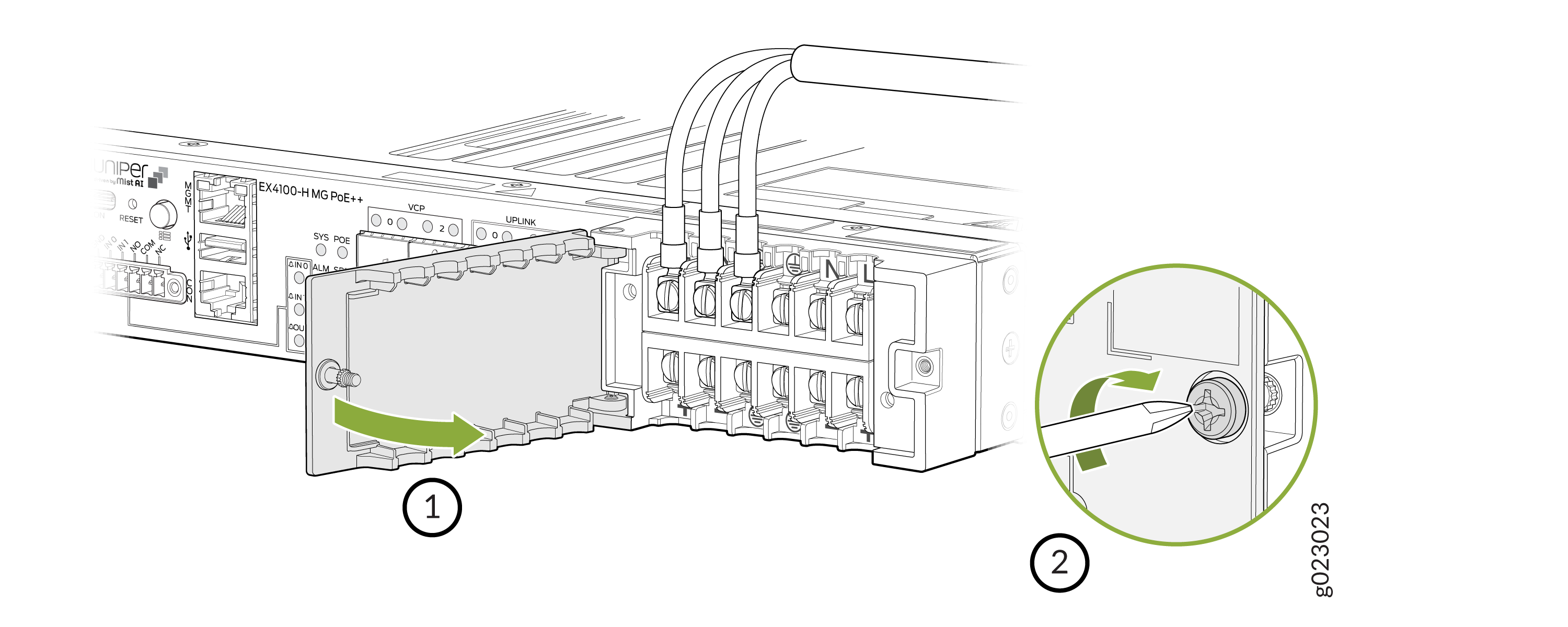
Loosen the screw of the power terminal door and open the power terminal
door. Recommended torque is 4.5 +/- 0.5 Lb.in. Recommended screwdriver is
Phillips #2 screwdriver.
Figure 11: Open the power terminal door
-
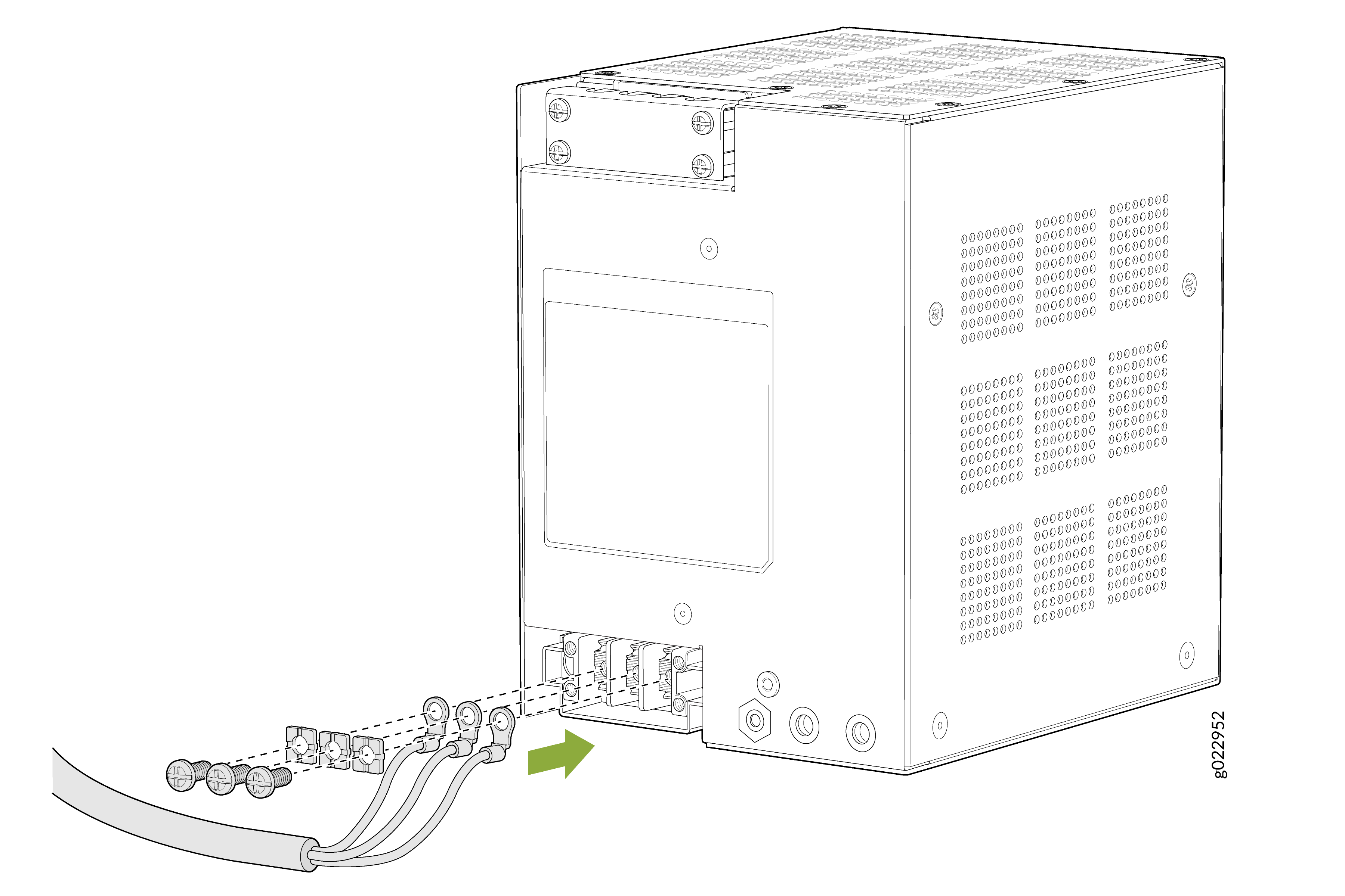
Assuming you have inserted at least one AC PSU into the switch at the rear;
so to connect the AC PSU to the main power source, loosen the screws marked
under the labels L, N, and G and insert the wires of the AC power cord into
the slots behind the screws. Tighten the screws and secure the connections.
Note that during this procedure, do not plug in the AC power cord into an AC
power source; do it only after securing the connections and securing the
terminal door.
Note:
Recommended torque is 7 +/- 0.5 Lb.in. Recommended screwdriver type is Phillips #2 or slotted/flat head 6 mm.
Figure 12: Connect AC PSU to the power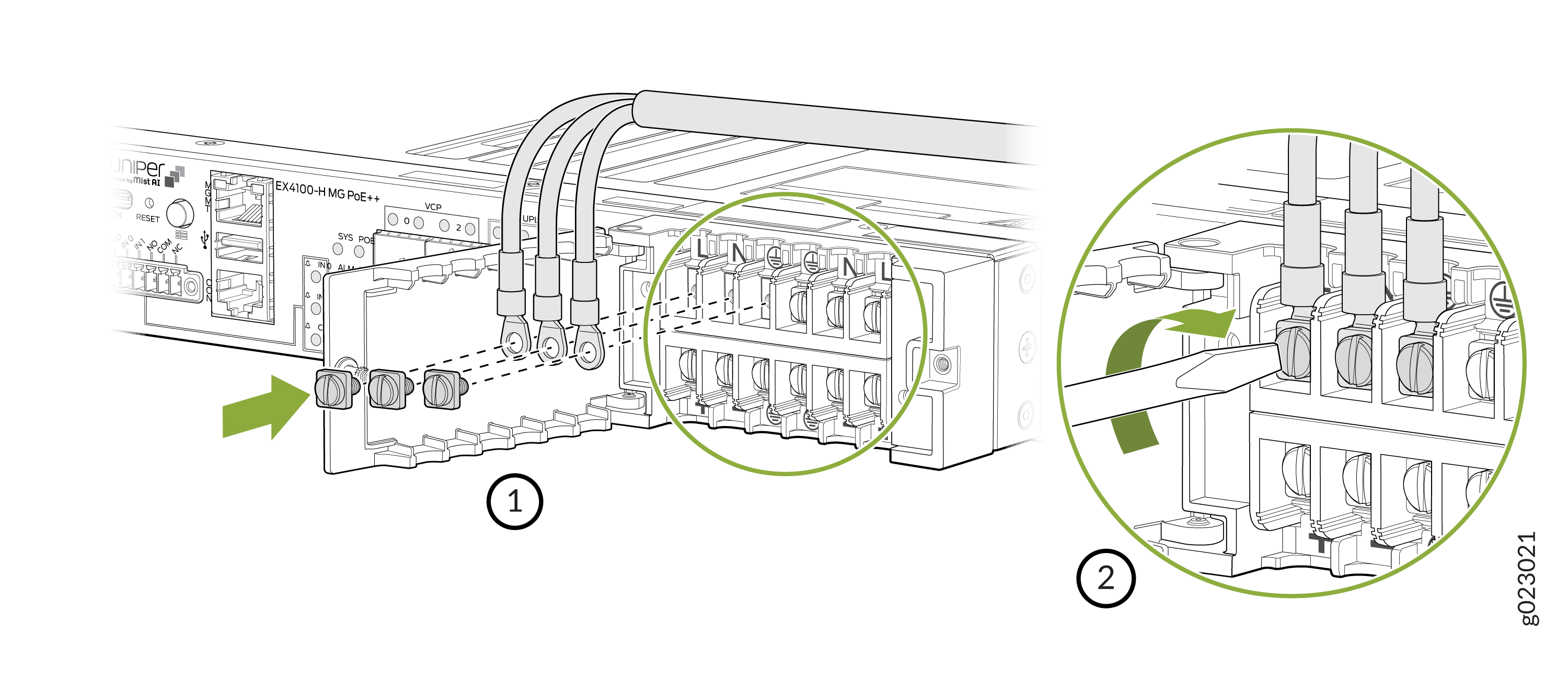
-
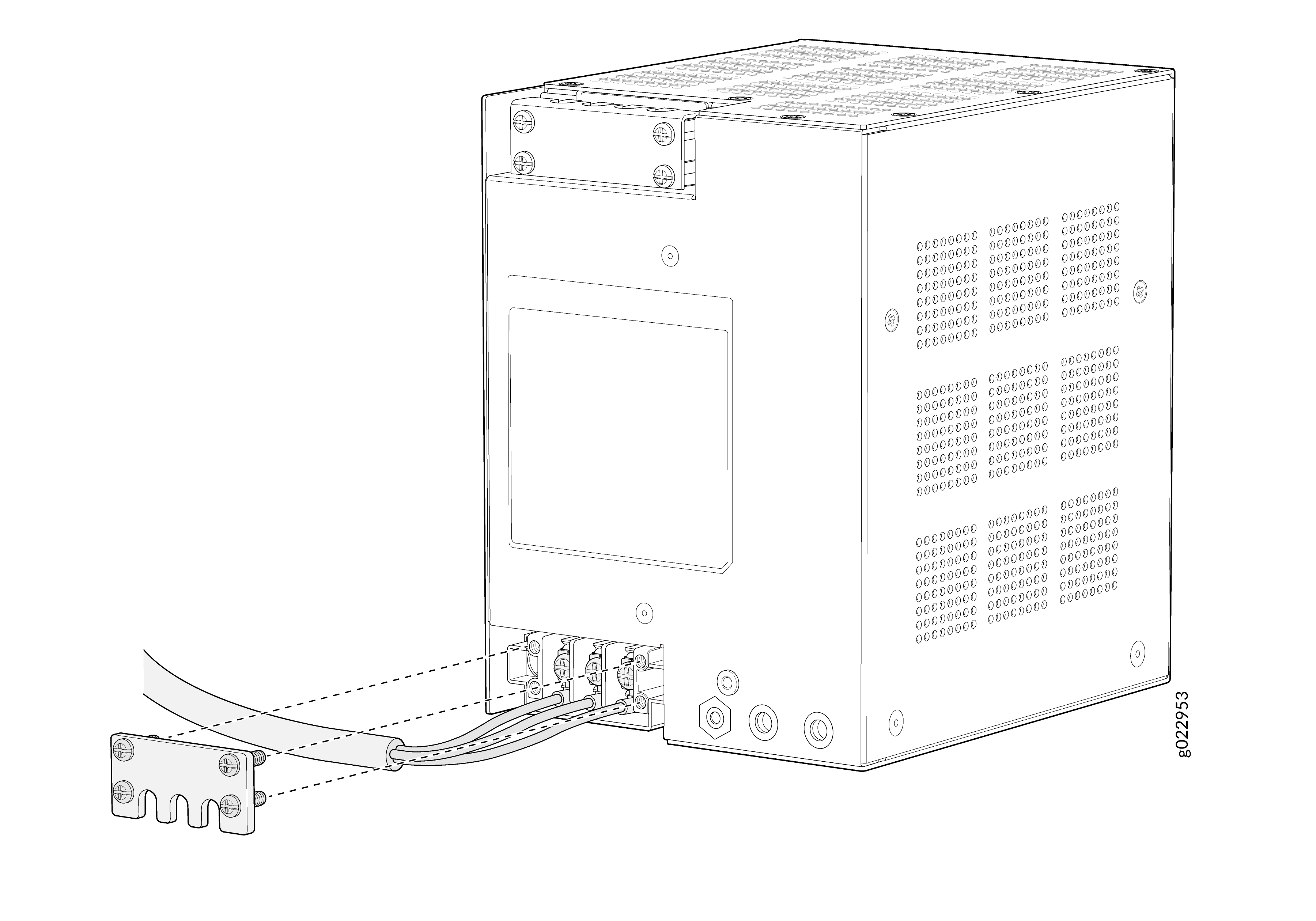
Assuming you have inserted at least one DC PSU into the switch at the rear;
to connect the DC PSU to the main power source, loosen the screws marked
under the labels DC+, DC-, and G and insert the wires of the DC power cord
into the slots behind the screws. Tighten the screws and secure the
connections. Note that during this procedure, to not plug in the DC power
cord into a DC power source, but to do it only after securing the
connections and securing the terminal door.
Note:
Recommended torque is 7 +/- 0.5 Lb.in. Recommended screwdriver type is Phillips #2 or slotted/flat head 6 mm.
Figure 13: Connect DC PSU to power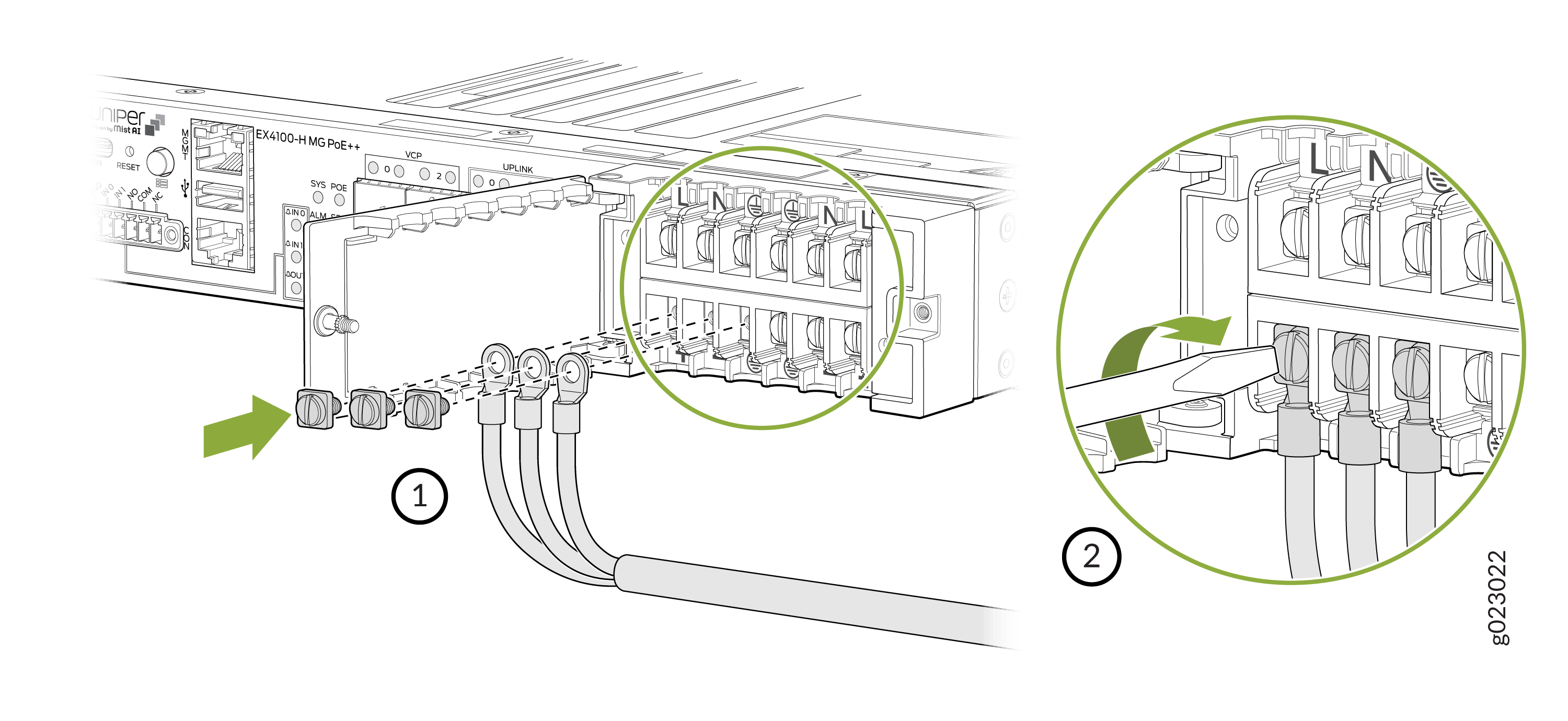
-
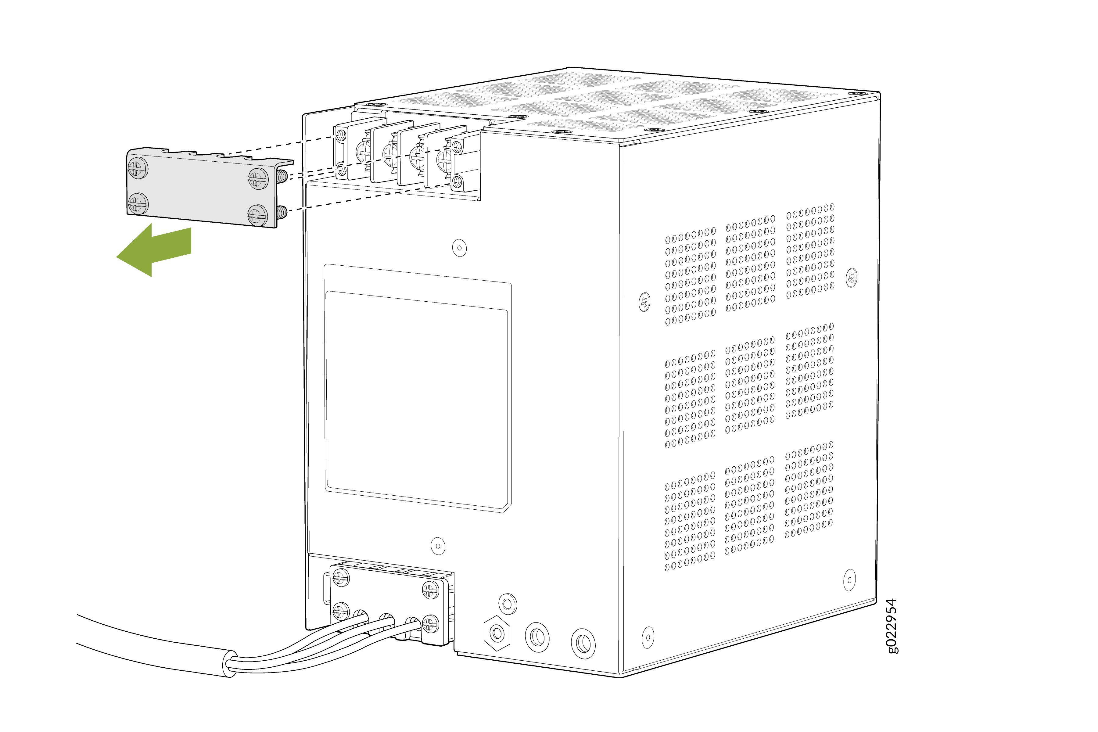
Shut the terminal door and tighten the screw of the terminal door.
Recommended torque is 4.5 +/- 0.5 Lb.in. Recommended screwdriver is Phillips
#2 screwdriver.