ON THIS PAGE
EX4100-H Chassis
Chassis Physical Specifications for EX4100-H Switches
The EX4100-H switch chassis is a rigid sheet-metal structure that houses all components of the switch Table 1 summarizes the physical specifications of the EX4100-H switch chassis.
|
Model |
Chassis Height |
Chassis Depth |
Chassis Width |
Chassis Weight |
|
|---|---|---|---|---|---|
|
EX4100-H-12MP |
6 in. (15.24 cm) |
5.3 in. (13.40 cm) |
4.4 in. (11.17 cm) |
5.22 lb (2.37 kg) |
|
|
EX4100-H-24MP |
1.7 in. (4.33 cm) |
With AC PSU - 14.96 in. (37.99 cm) With DC PSU - 15.35 in. (38.99 cm) |
17.28 in. (43.90 cm) |
With no PSU - 15.25 lb (6.92 kg) With 1 AC PSU - 18.40 lb (8.35 kg) With 1 DC PSU - 18.45 lb (8.37 kg) |
|
|
EX4100-H-24F |
1.7 in. (4.33 cm) |
14.96 in. (37.99 cm) |
17.28 in. (43.90 cm) |
With no PSU - 17.79 lb (8.07 kg) With AC PSU - 20.28 lb (9.20 kg) With DC PSU - 20.24 lb (9.23 kg) |
|
|
Switch Model |
Power Supply Unit Weight |
|||||
|---|---|---|---|---|---|---|
|
340 W external AC PSU |
340 W external DC PSU |
340 W FRU AC PSU |
340 W FRU DC PSU |
90 W FRU AC PSU |
90 W FRU DC PSU |
|
|
EX4100-H-12MP |
4.52 lb (2.05 kg) |
4.07 lb (1.85 kg) |
NA |
NA |
NA |
NA |
|
EX4100-H-24MP |
NA |
NA |
3.15 lb (1.43 kg) |
3.19 lb (1.45 kg) |
NA |
NA |
|
EX4100-H-24F |
NA |
NA |
NA |
NA |
2.49 lb (1.13 kg) |
2.55 lb (1.16 kg) |
Chassis Status LEDs on EX4100-H Switches
EX4100-H switches have four chassis status LEDs (labeled SYS, ALM, MST, and CLD) on the rightside of the front panel .
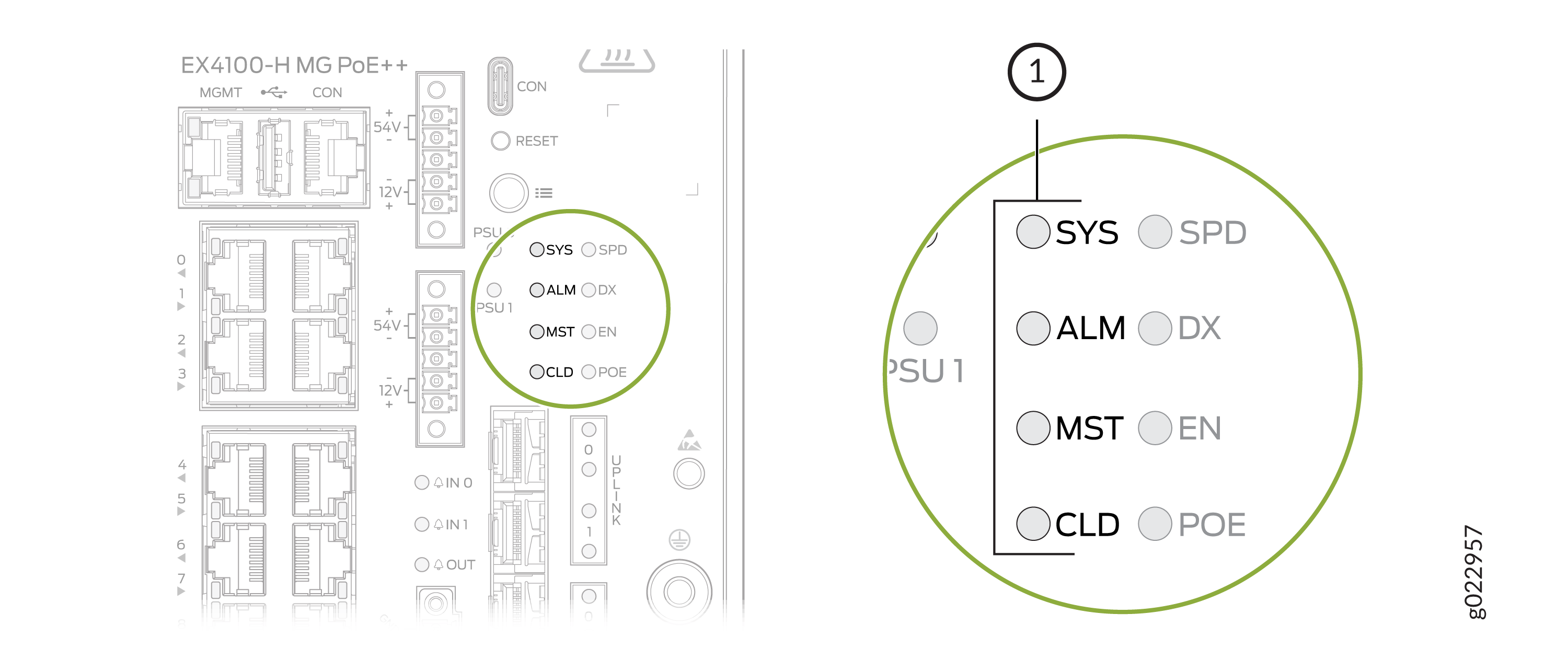
1 — Chassis status LEDs |
1 — Chassis status LEDs |
Table 3 describes the chassis status LEDs labeled
SYS, ALM, and
MST on an EX4100-H switch. The table also describes the LED color patterns and
their status descriptions. You can view the colors of the LEDs remotely through the
CLI by issuing the show chassis led operational mode command. Note
that all LEDs can be lit simultaneously.
For information on the blink patterns of the CLD LED, which provide the cloud connection status of the switch, see Cloud Ready LED Blink Patters and to understand how the cloud connection works, see Cloud Connection Process.
|
LED Label |
Color |
State and Description |
|---|---|---|
|
SYS |
Green |
|
|
Unlit |
The switch is powered off or is halted. |
|
|
ALM |
Red |
A major hardware fault, such as a temperature alarm or a power failure alarm, occurred, and the switch is halted. A major alarm indicates a critical error condition that requires immediate attention (see Chassis Component Alarm Conditions on EX4100-H Switches). |
|
Amber |
A minor alarm, such as a software or a hardware error, occurred. Power off the switch and then power it back on. Monitor the switch to see whether it is working properly. A minor alarm indicates a non-critical condition that requires monitoring or maintenance. A minor alarm that is left unchecked might cause interruption in service or performance degradation. |
|
|
Unlit |
No alarm is in effect, or the switch is halted. |
|
|
MST |
Green |
In a standalone switch:
|
|
In a Virtual Chassis configuration:
|
When issuing show system alarms, only the ALM LED of the
master switch in a Virtual Chassis
system glows to display the alarm state. Backup switch and linecard ALM LEDs
will be unlit. However, when issuing show chassis alarms, ALM
LED glows on all of the individual member switches, displaying their individual
alarm states.
For Virtual Chassis deployments managed from the cloud, the CLD LED on individual Virtual Chassis members will reflect the state of the Master, except when a software download is in progress. When a software download is in progress, the CLD LED on a Virtual Chassis member will display the Junos OS upgrading LED pattern and color.
LEDs on the Management Port on EX4100-H Switches
The management port, labeled MGMT, on the front panel of EX4100-H switches has two LEDs that indicate the link activity and port status (see Figure 3 ).
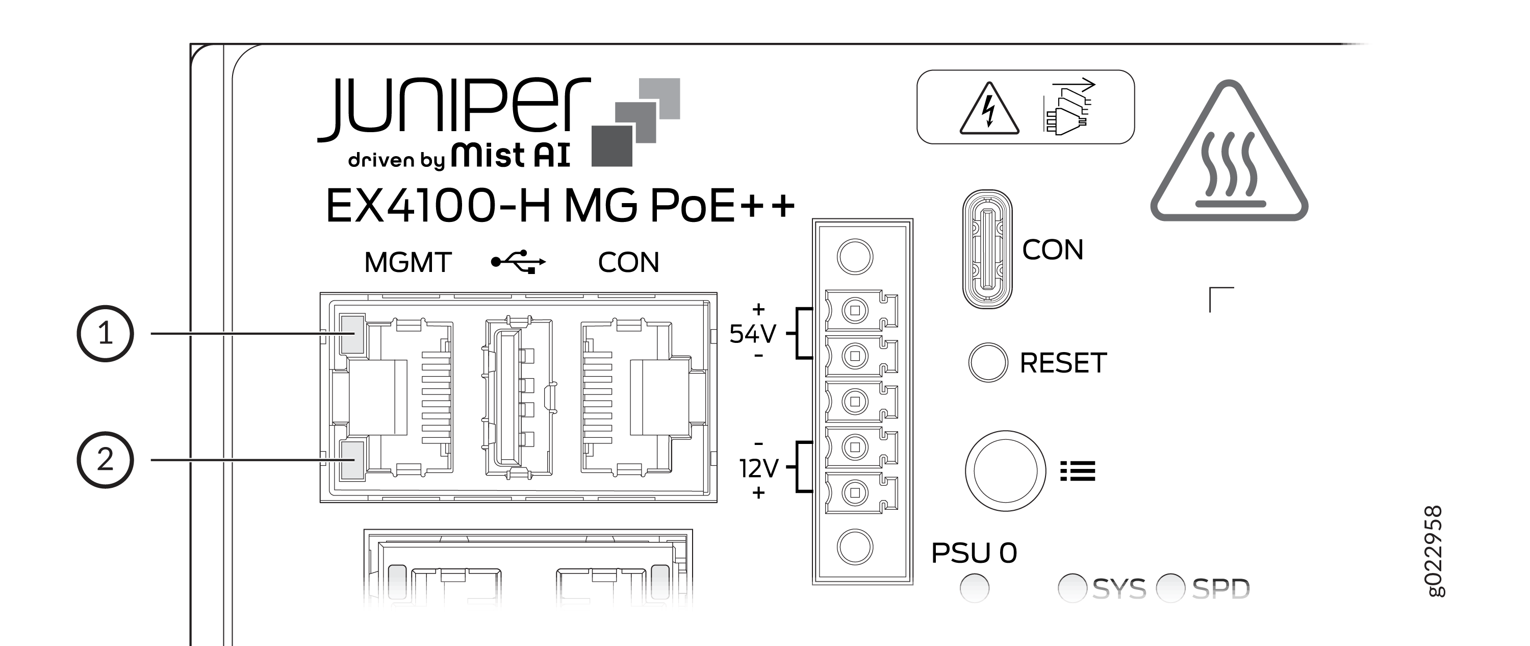
1 — Link activity LED | 2 — Status LED |

1 — Link activity LED | 2 — Status LED |
Table 4 describes the LEDs on the management port.
|
LED |
Color |
State and Description |
|---|---|---|
|
Link activity |
Green |
|
|
Status |
Green |
Indicates the speed:
|
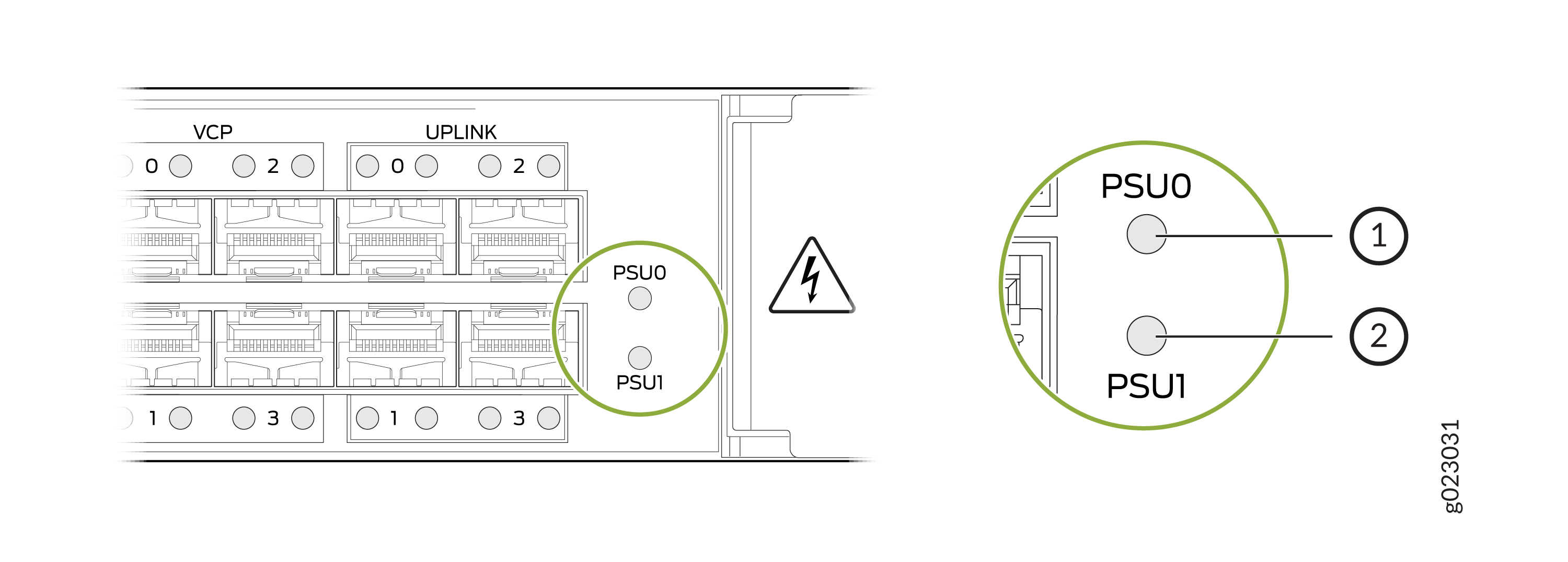
PSU Status LEDs on the Switch Chassis
The PSU 0 and PSU 1 LEDs on the chassis display status of the external PSUs connected to the switch. See Figure 5.
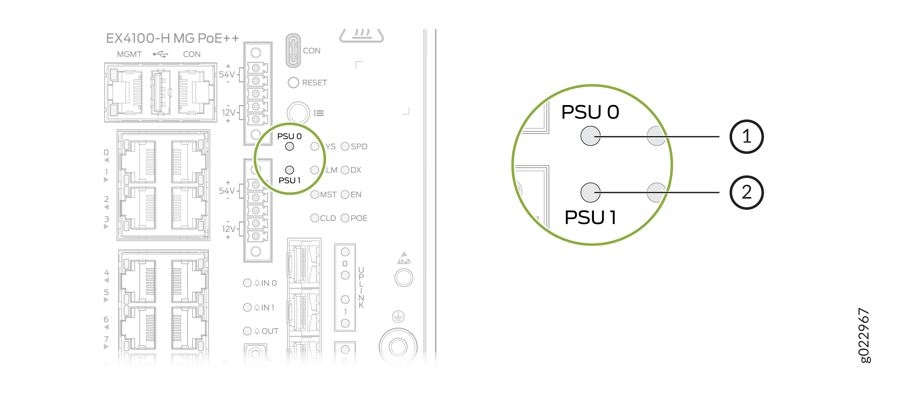
1 — PSU 0 LED | 2 — PSU 1 LED |
1 — PSU 0 LED | 2 — PSU 1 LED |
Table 5 describes the colors and statuses of the LEDs.
|
PSU LED Label |
Color |
State and Description |
|---|---|---|
|
PSU 0 PSU 1 |
Green |
54 V output OK or 12 V output OK. The external PSU is connected to the PSU connector (PSU 0 and/or PSU 1) on the switch. |
|
Off |
Status can be one of the following
|
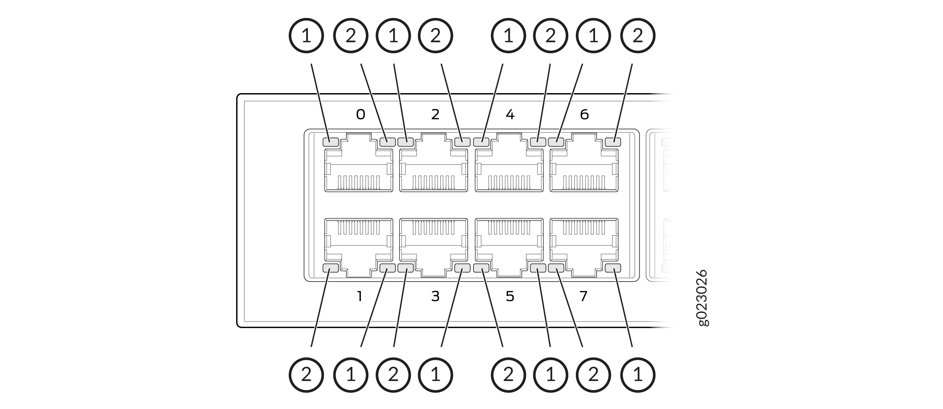
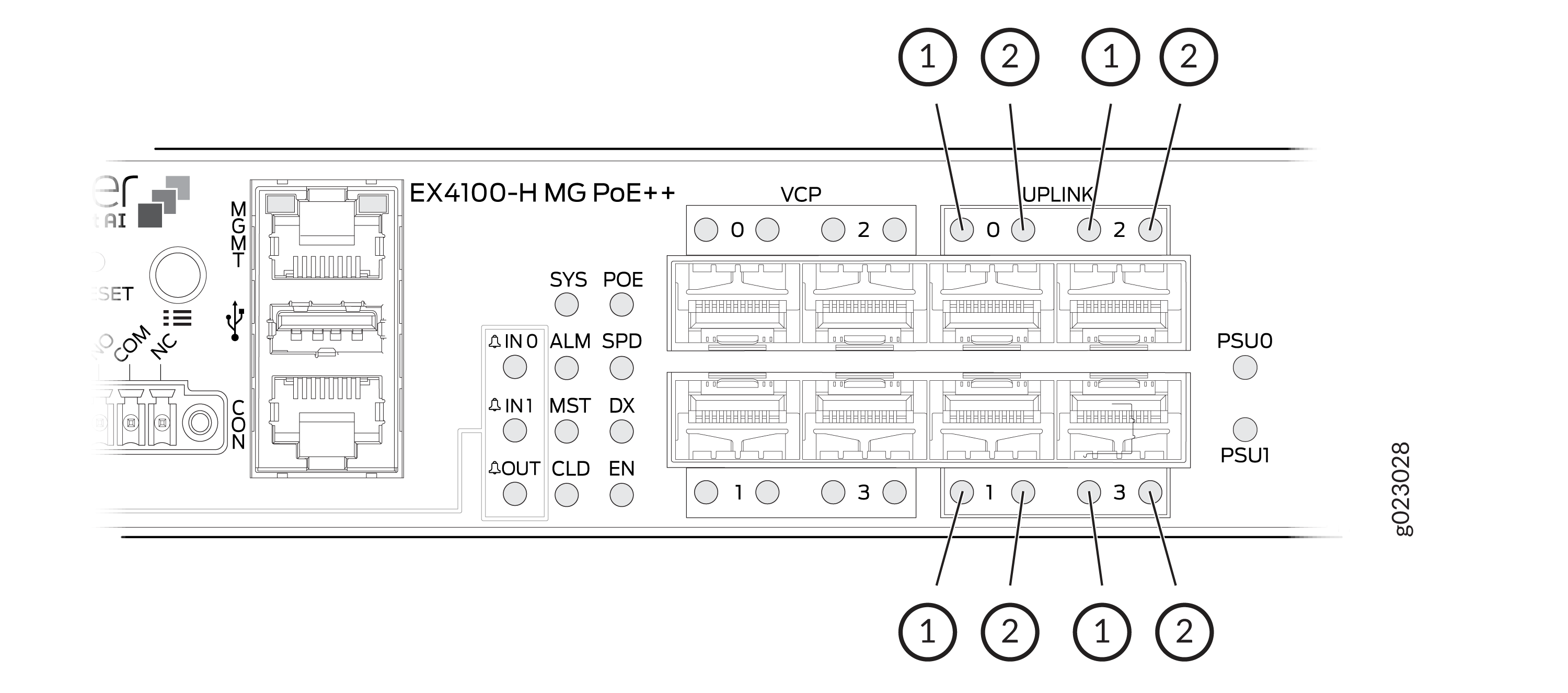
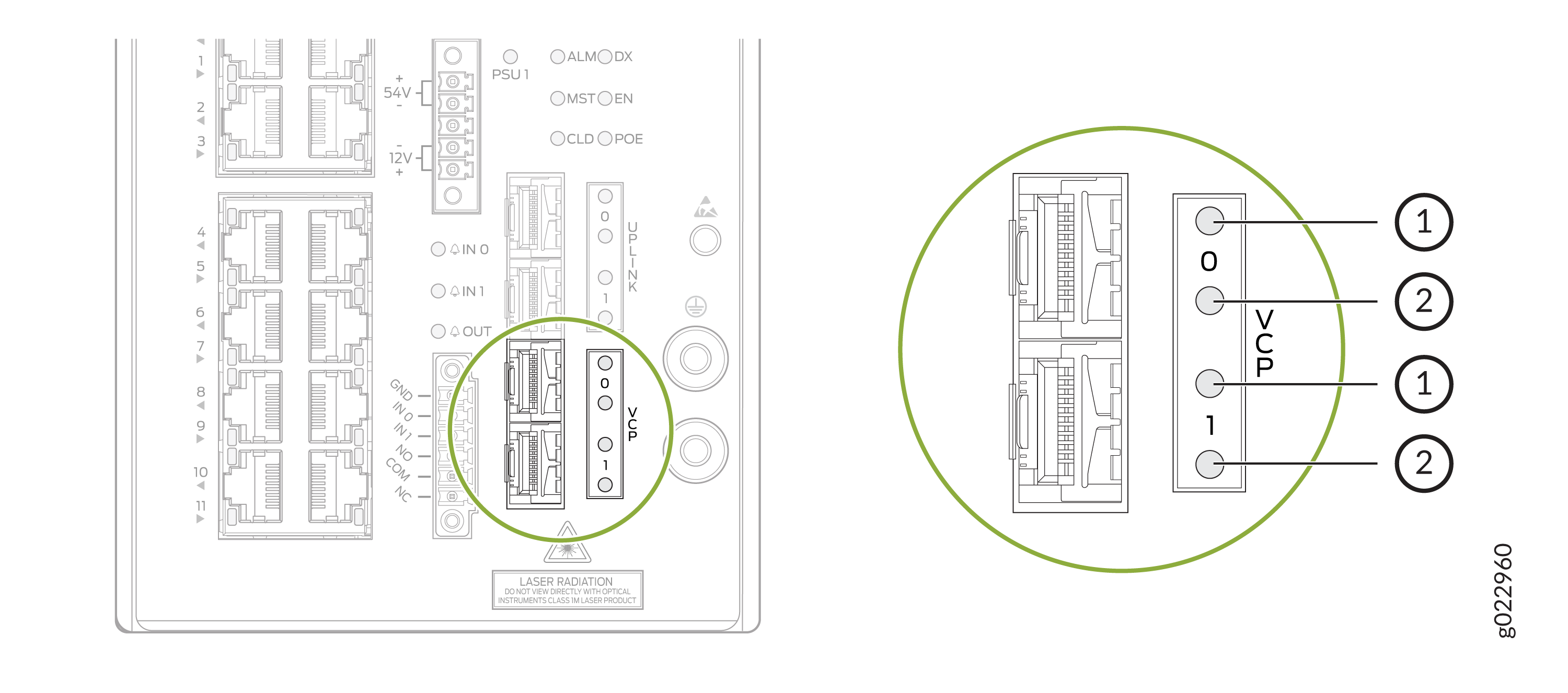
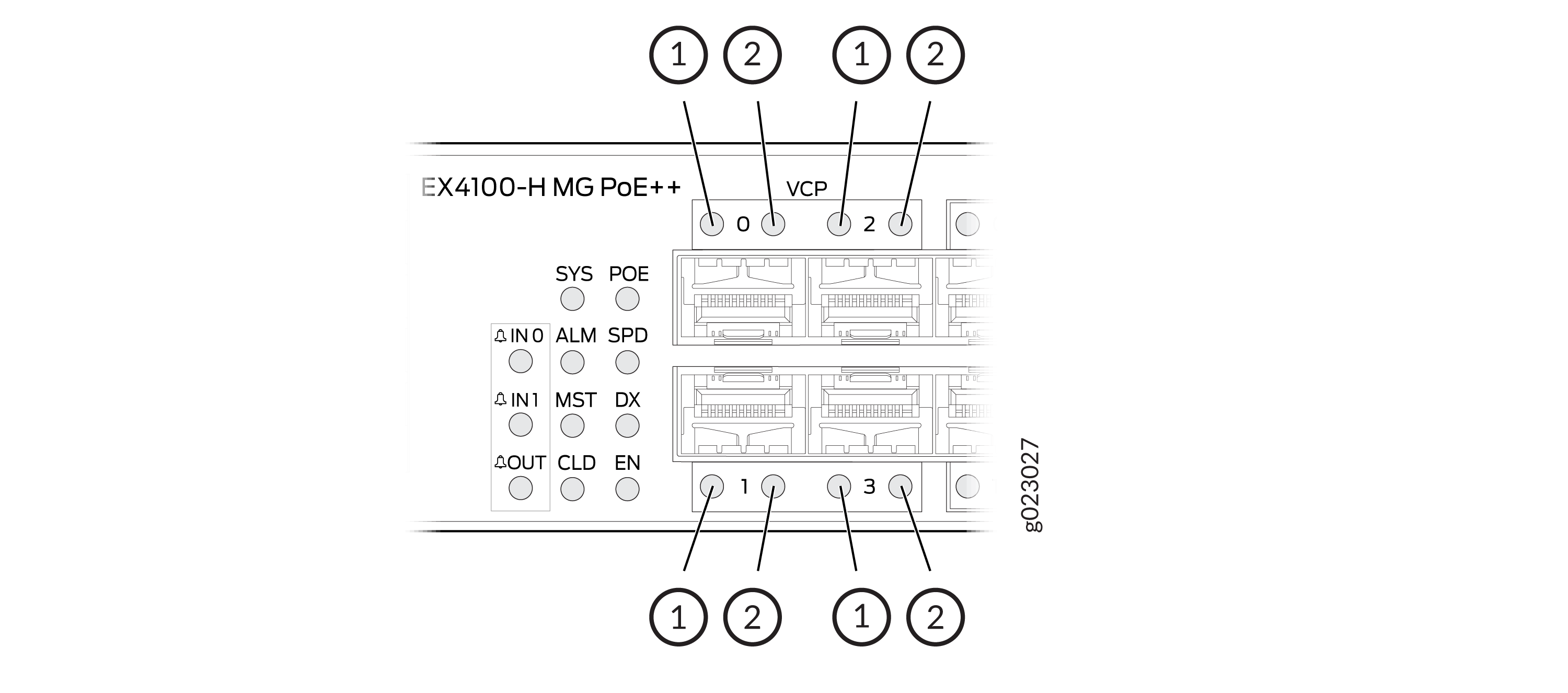
LEDs on the RJ-45 Network Ports, Virtual Chassis Ports, and Uplink Ports on EX4100-H Switches
The LEDs on the RJ-45 network ports, SFP+ uplink ports, and SFP+ Virtual Chassis ports on EX4100-H switches show the link activity and port status.
LEDs on the Network Ports
The figures in this section show the LEDs on their respective ports:
-
Figure 7 shows the LEDs on the RJ-45 network ports on EX4100-H switches.
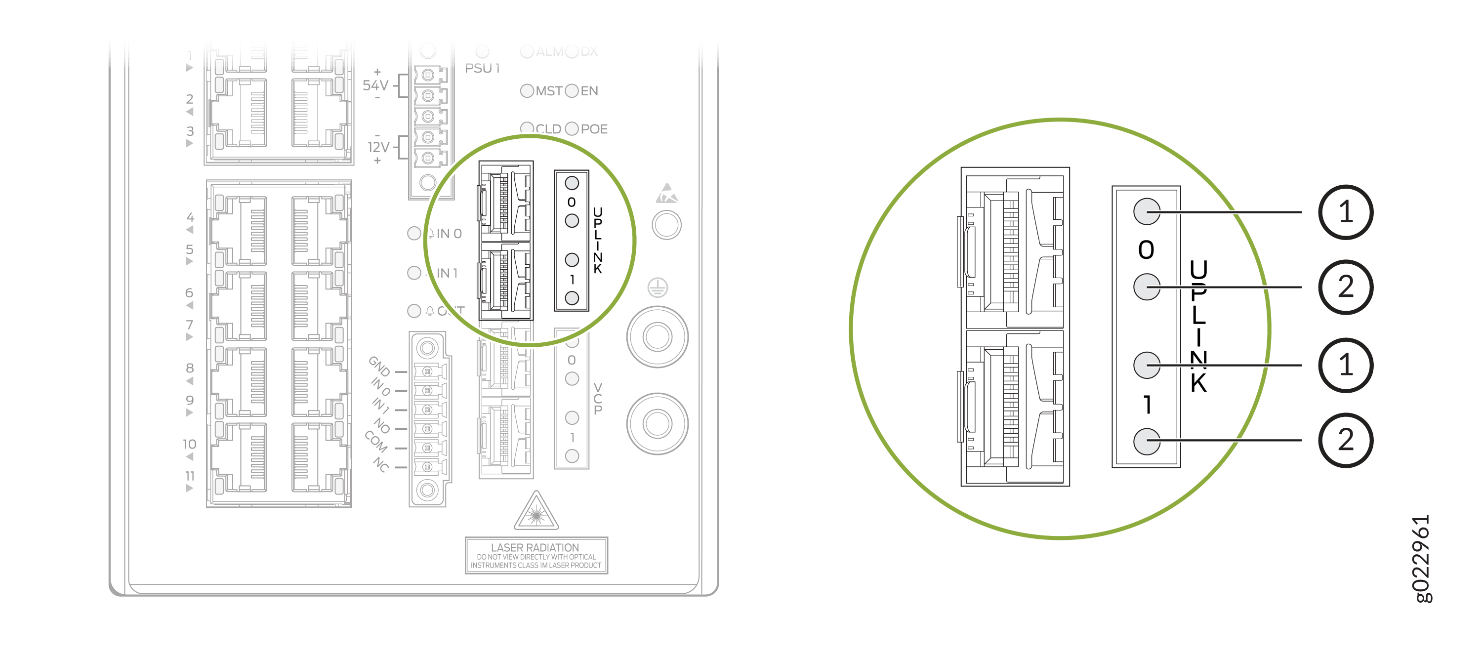
-
Figure 9 shows the LEDs on the SFP+ uplink ports.
-
Figure 11 shows the LEDs on the SFP+ Virtual Chassis ports.
-
Table 6 describes the link activity LED state and description on the RJ-45 ports, SFP+ uplink ports, and SFP+ Virtual Chassis Ports.
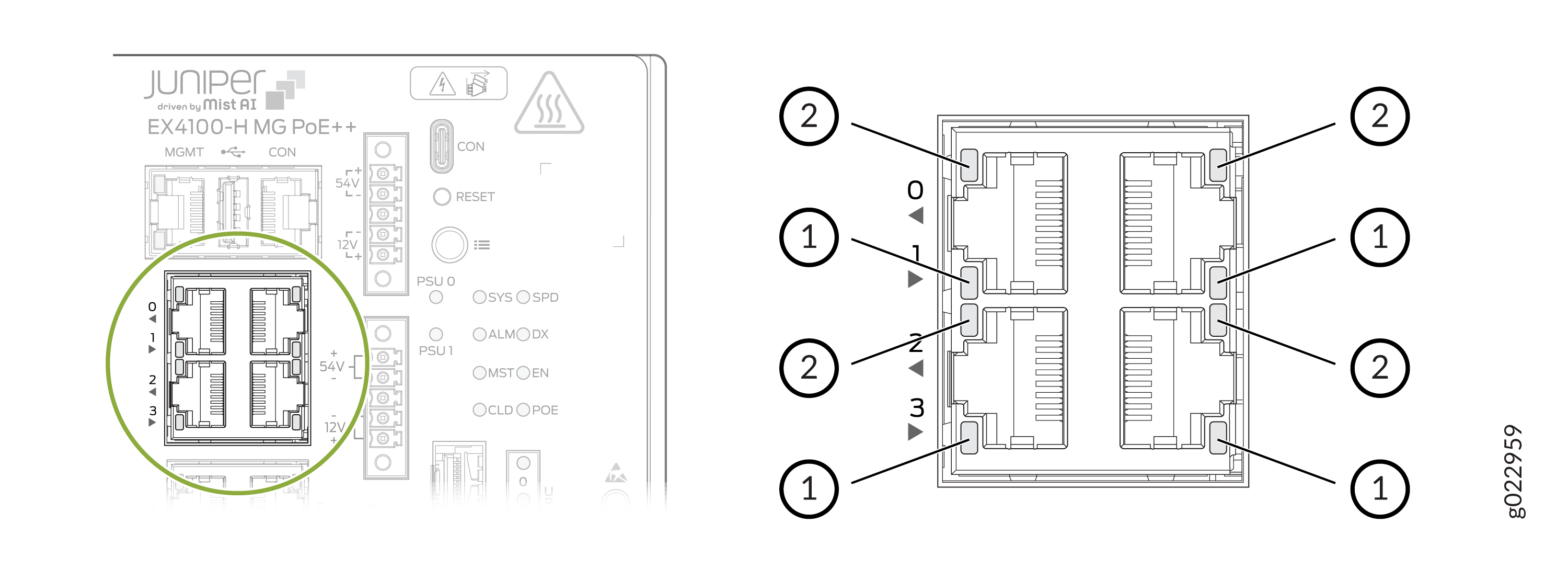
1 — Link activity LED | 2 — Status LED |
1 — Link activity LED | 2 — Status LED |
1 — Link activity LED | 2 — Status LED |
1 — Link activity LED | 2 — Status LED |
1 — Link activity LED | 2 — Status LED |
1 — Link activity LED | 2 — Status LED |
|
LED Color |
State and Description |
|---|---|
|
Green |
|
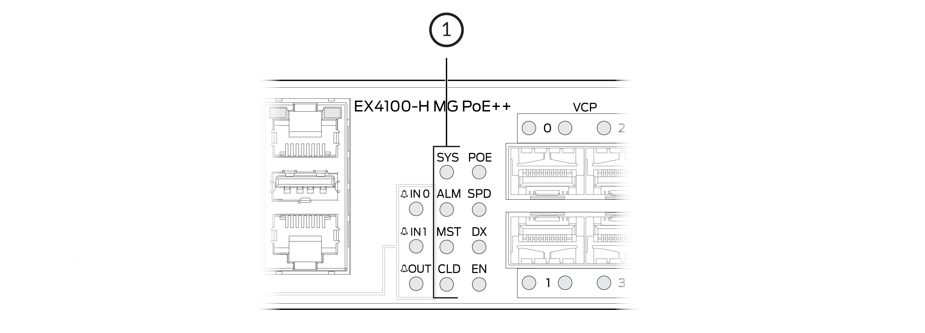
EX4100-H switches have network port mode LEDs (labeled SPD, DX, EN, and POE) on the right side of the front panel (see Figure 13). These LEDs indicate the status of the network ports. Use the mode button on the right side of the front panel to toggle the status LEDs. You toggle the status LEDs to show the different port parameters for the network ports. The LED that is lit indicates the port parameter. Table 7 describes the status LEDs.
The LED labeled PoE is not available on switch models with network ports that do not provide PoE.
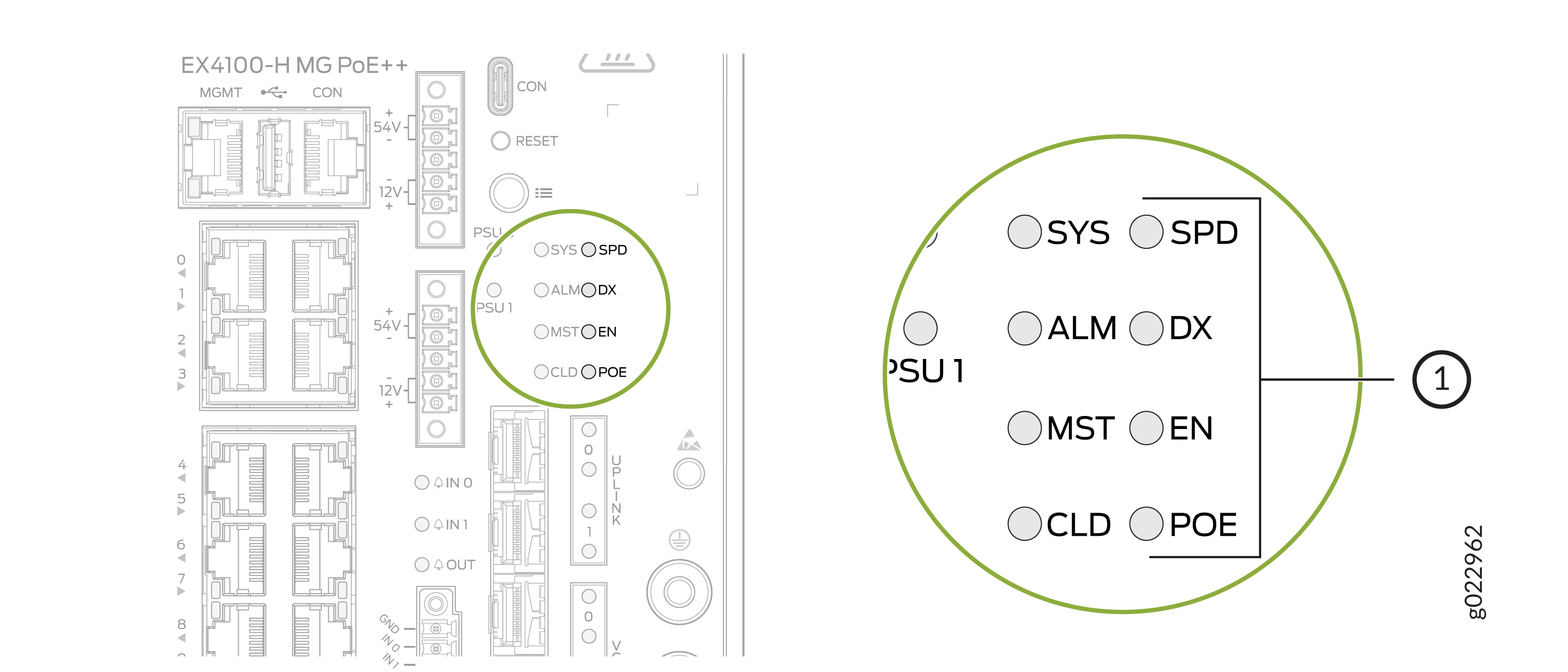
1 — Port Mode LEDs |
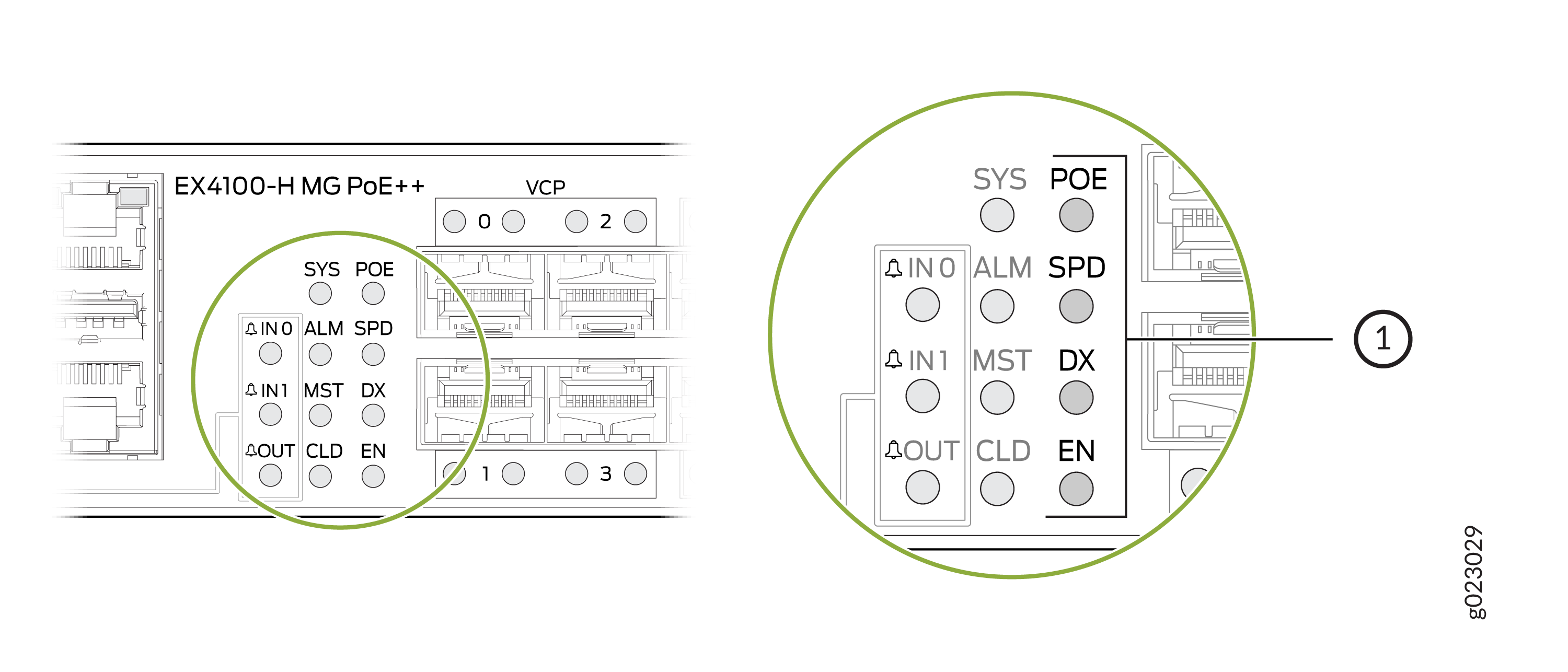
1 — Port Mode LEDs |
|
LED |
Color |
State and Description |
|---|---|---|
|
SPD |
Green |
Indicates the speed.
|
|
Amber |
On steadily—2.5 Gbps |
|
|
DX |
Green |
Indicates the duplex mode.
|
|
EN |
Green |
Indicates the administrative status.
|
|
POE |
Green |
Indicates the PoE mode.
|
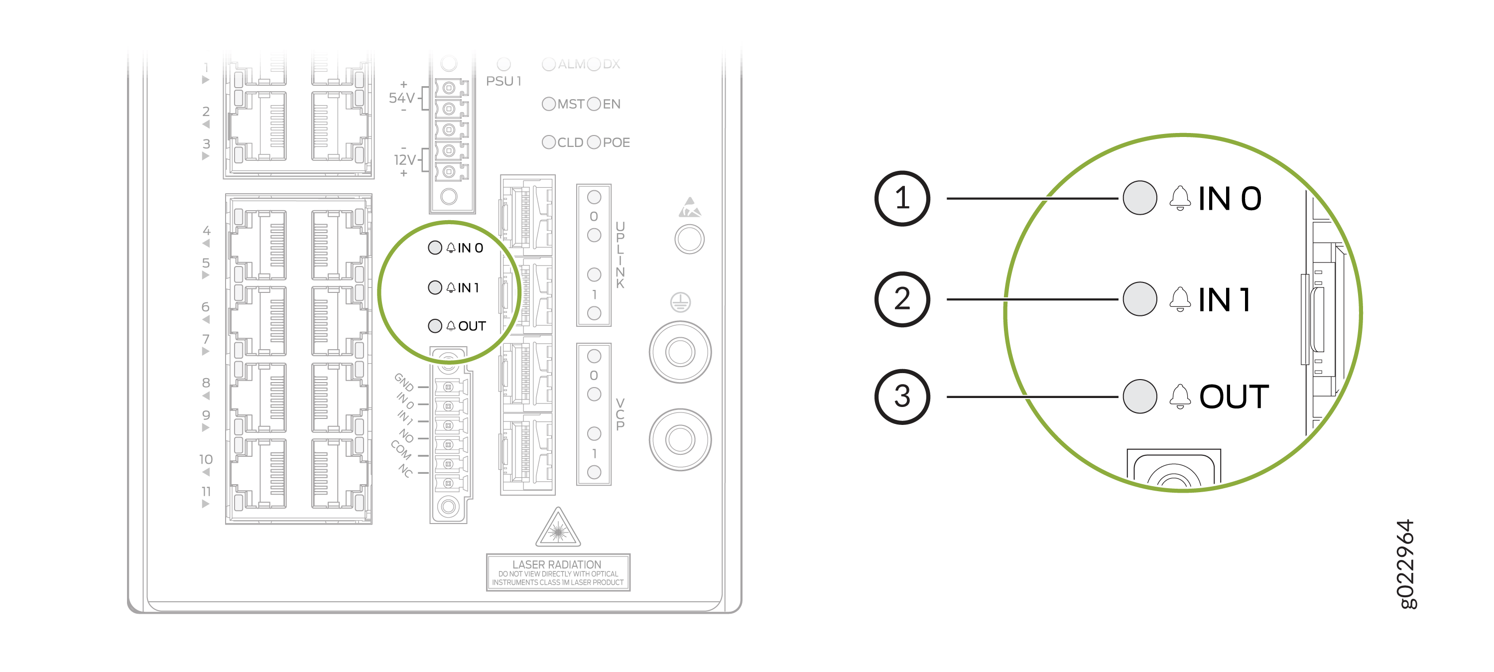
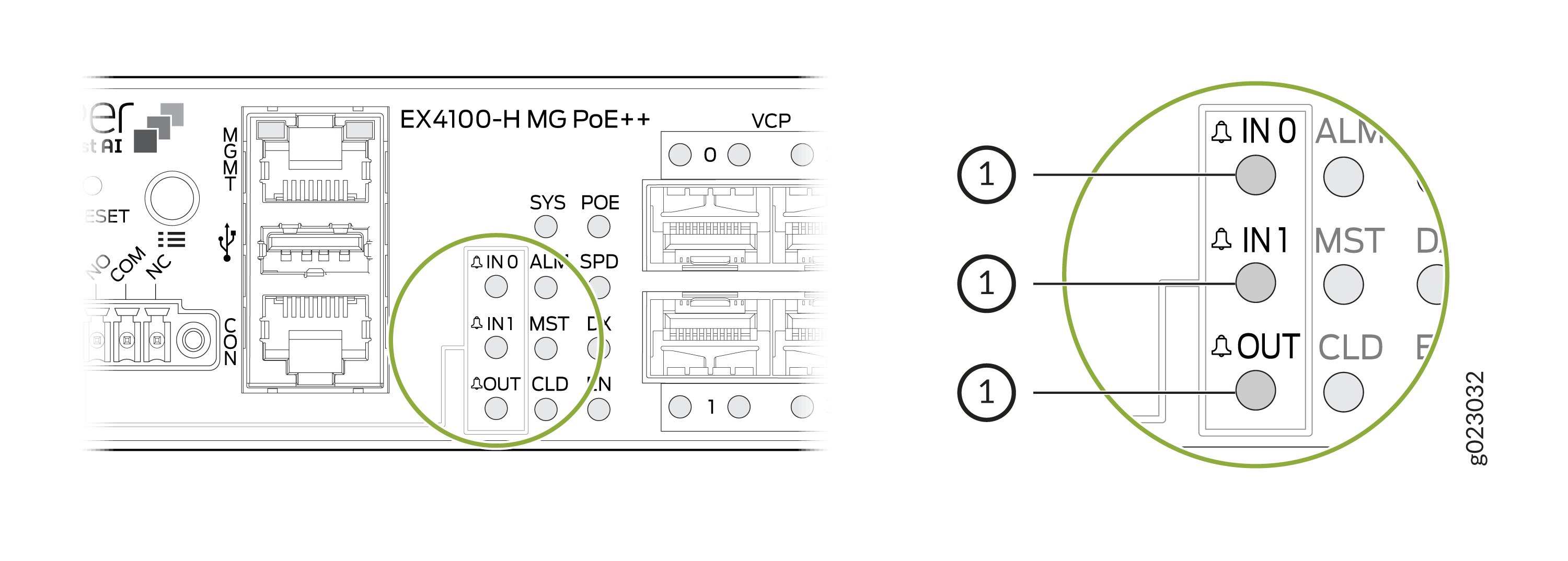
Dry Contact Alarm LEDs
The EX4100-H switch has three LEDs to indicate alarm conditions. Two LEDs are for input alarms (IN0 AND IN1) and one LED is for output alarm (OUT).
|
OUT |
|
|---|---|
|
Color |
System Status |
|
Off |
Alarm OUT not configured, or the switch in off mode. |
|
Green |
Alarm OUT configured, no alarm detected, or an input alarm detected with severity NONE. |
|
Red |
Output port triggered or activated. |
|
IN0 and IN1 |
|
|---|---|
|
Color |
System Status |
|
Off |
Alarm IN0 or IN1 not configured. |
|
Green |
Alarm IN0 or IN1 configured, no alarm detected. |
|
Blinking red |
Major alarm detected. |
|
Red |
Minor alarm detected. |