Connect the EX4100-H-12T to External Devices
This topic guides you on how to connect your EX4100-H-12T switch to external mangement or timing devices.
You can monitor and manage the EX4100-H-12T switch by using a dedicated management channel. Use the management port to connect your device to the management device.
You can also connect the EX4100-H-12T switch to external clocking and timing devices.
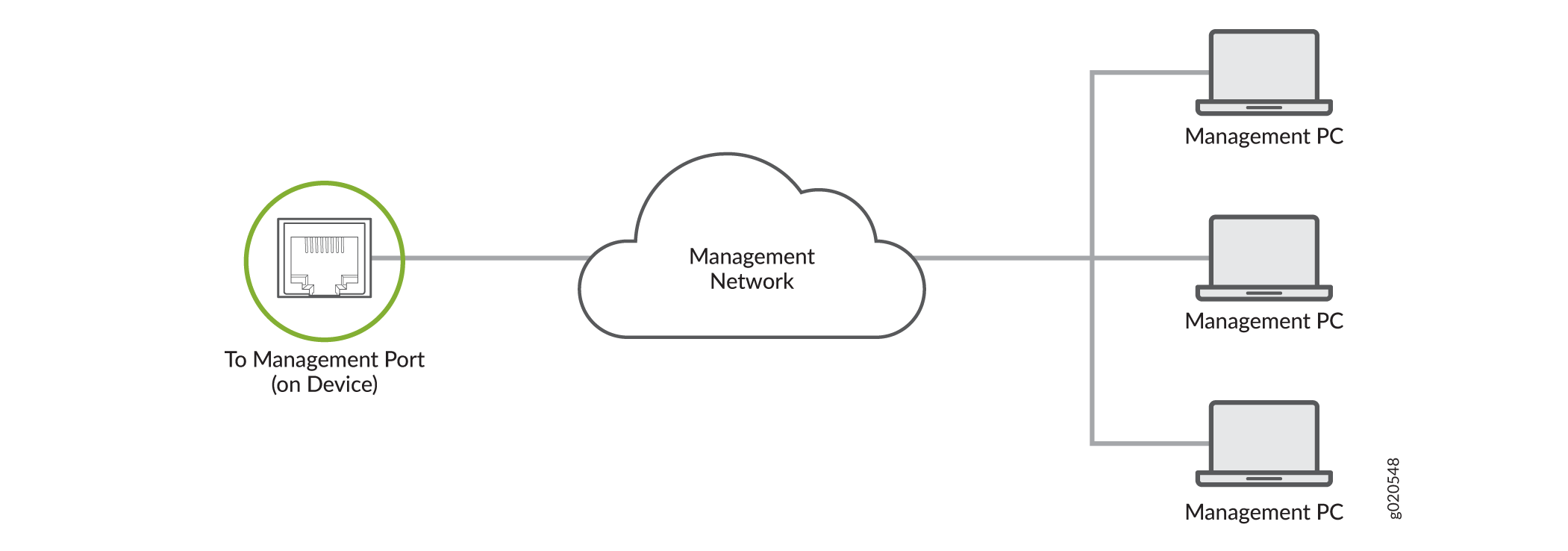
Connect the EX4100-H-12T to a Network for Out-of-Band Management
Ensure that you have an Ethernet cable that has an RJ-45 connector at each end.
To connect a device to a network for out-of-band management:
-
Connect the other end of the cable to the management device.
Figure 1: Connect Your Device to a Network for Out-of-Band Management
Connect the EX4100-H-12T to a Management Console Using an RJ-45 Connector
Ensure that you have an Ethernet cable that has an RJ-45 connector at either end. You will also need the appropriate adapter (not provided) depending upon your console server or management console.
You can separately order the following adapters from Juniper Networks:
-
RJ-45 to DB-9 adapter (JNP-CBL-RJ45-DB9)
-
RJ-45 to USB-A adapter (JNP-CBL-RJ45-USBA)
-
RJ-45 to USB-C adapter (JNP-CBL-RJ45-USBC)
If you want to use the RJ-45 to USB-A or RJ-45 to USB-C adapter you must have X64 (64-Bit) Virtual COM port (VCP) driver installed on your PC. See https://ftdichip.com/drivers/vcp-drivers/ to download the driver.
To connect the device to a management console:
-
Connect the other end of the cable to the console server or PC.
Figure 2: Connect Your Device to a Management Console Through a Console Server
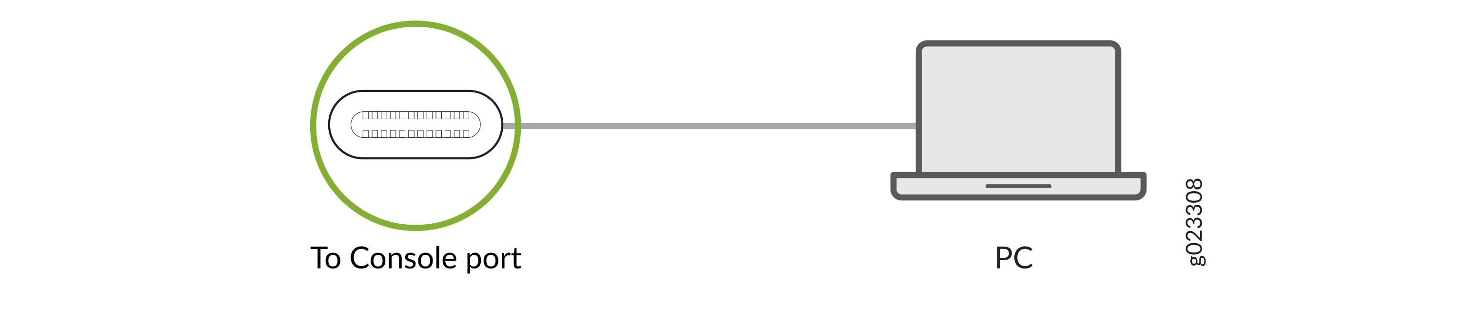
 Figure 3: Connect Your Device Directly to a Management Console
Connect Your Device to a Management Console Using a USB-C Connector
Ensure that you have a USB cable that has a USB-C connector at either end. You will also need the appropriate adapter (not provided) depending upon your console server or management console.
Ensure that the USB-to-serial driver is installed on the host machine.
By default, the RJ-45 is the active console port. You must configure the USB-C console port before using it. Set the HyperTerminal properties of the console server or management console as follows:
-
Baud rate—9600
-
Flow control—None
-
Data—8
-
Parity—None
-
Stop bits—1
-
DCD state—Disregard
To connect the device to a management console:
-
Connect the other end of the cable to the console server or management
console.
Figure 4: Connect Your Device to a Management Console Through a Console Server
 Figure 5: Connect Your Device Directly to a Management Console