Connect the EX4100-F to Power
Connect Earth Ground to an EX4100-F Switch
To ensure proper operation and to meet safety and electromagnetic interference (EMI) requirements, you must connect EX4100-F switches to earth ground before you connect power to the switch. You must use the protective earthing terminal on the switch chassis to connect the switch to earth ground (see Figure 1 and Figure 2.
You must install the EX4100-F switches in a restricted-access location and ensure that the chassis is always properly grounded. EX4100-F switches have a two-hole protective grounding terminal on the rear panel of the chassis. Under all circumstances, use this grounding connection to ground the chassis. For AC-powered systems, you must also use the grounding wire in the AC power cord along with the two-hole grounding lug connection. This tested system meets or exceeds all applicable EMC regulatory requirements with the two-hole protective grounding terminal.
Ensure that a licensed electrician has attached the appropriate grounding lug to the grounding cable that you supply. Using a grounding cable with an incorrectly attached lug can damage the switch.
Before you connect earth ground to a EX4100-F switch, ensure that you have parts and tools listed in Table 1 available:
| Item | Switch Models | Description |
|---|---|---|
| Earthing terminal location |
All EX4100-F switches |
Rear panel of the chassis |
| Grounding cable requirements | All EX4100-F switches | 8 AWG (3.26 mm²), minimum 90° C wire,
or as permitted by the local code—not provided
|
| Grounding lug specifications | EX4100-F-24P, EX4100-F-24T, EX4100-F-48P, and EX4100-F-48T switches |
Panduit LCD8-14A-L or equivalent—not provided |
| EX4100-F-12P and EX4100-F-12T switches | Panduit LCD8-10A-L—not provided | |
| Screws to secure the grounding lug | EX4100-F-Connecting an AC Power Cord Retainer Clip to the AC Power Cord Inlet on an EX4100 Switch24P, EX4100-F-24 T, EX4100-F-48P, and EX4100-F-48T switches | Two M5X10mm screws with washer—seperately orderable |
| EX4100-F-12P and EX4100-F-12T switches | 10-32 screws—not provided | |
| Tools required | All EX4100-F switches |
Number 2 Phillips (+) screwdriver—not provided Electrostatic discharge (ESD) grounding strap—not provided |
To ground the EX4100-F switch to a proper ground reference:
-
Place the grounding lug attached to the grounding cable over the protective
earthing terminal on the rear panel (see Figure 1 and Figure 2).
Figure 1: Connect a Grounding Cable to an EX4100-F-24P, EX4100-F-24T, EX4100-F-48P, and EX4100-F-48T Switch
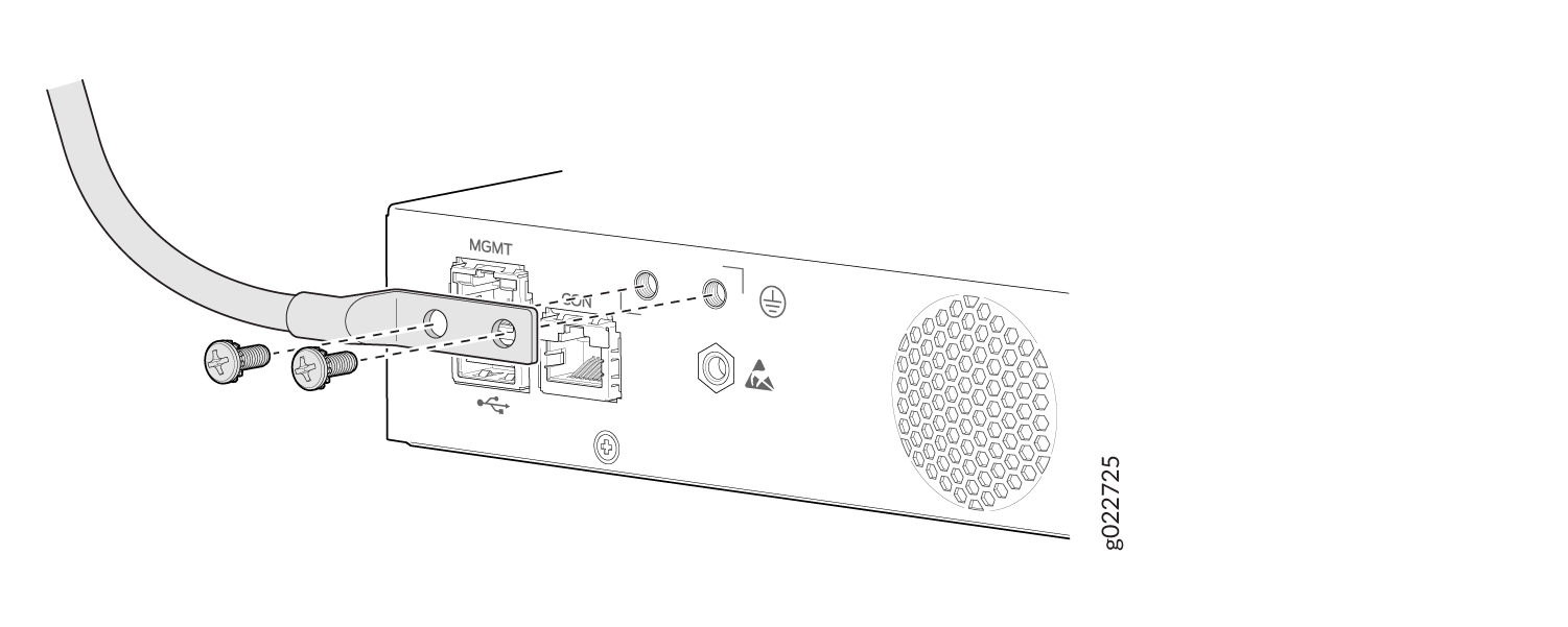 Figure 2: Connect a Grounding Cable to an EX4100-F-12P and EX4100-F-12T Switch
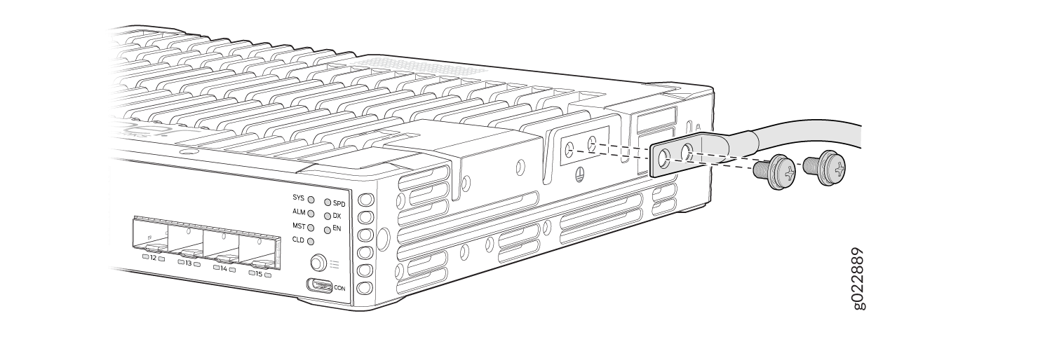
Connect AC Power to an EX4100-F Switch
These instructions apply to EX4100-F-24P, EX4100-F-24T, EX4100-F-48P, EX4100-F-48T, EX4100-24MP, and EX4100-48MP switches. Before you connect AC power, ensure that you have the following parts and tools available:
-
A power cord appropriate for your geographical location
-
A power cord retainer clip (provided with the switch)
Ensure that you have connected the device chassis to earth ground. The AC power cords also provide additional grounding when you connect the power supply in the switch to a grounded AC power outlet by using the AC power cord appropriate for your geographical location (see Table 10).
For installations that require a separate grounding conductor to the chassis, have a licensed electrician complete this connection before you connect the switch to power. For instructions on connecting earth ground, see Connect Earth Ground to an EX4100-F Switch.
You install the power supply in the power supply slot on the rear panel of the switch.
To connect AC power to the switch:
- If the AC power source outlet has a power switch, set it to the OFF (0) position.
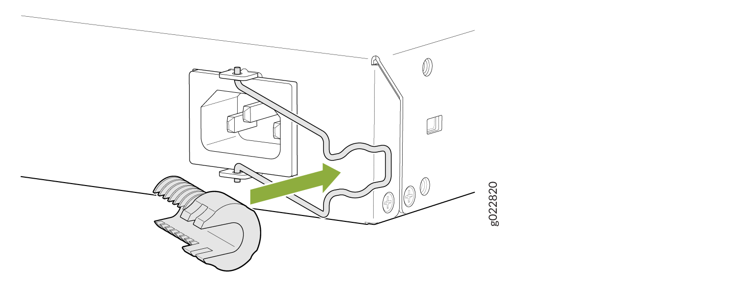
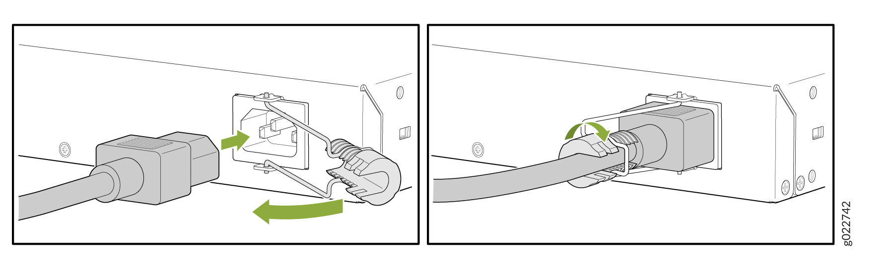
- Push the power cord into the slot in the adjustment nut of the power cord retainer clip. Turn the nut until it is tight against the base of the coupler and the slot in the nut is turned 90° from the top of the switch. See Figure 3 and Figure 4.
- Insert the power cord plug into an AC power source outlet.
- If the AC power source outlet has a power switch, set it to the ON (|) position.
Connect AC power to an EX4100-F-12P and EX4100-F-12T Switch
Before you connect power to the switch, ensure that you have the following parts and tools available:
-
A power cord appropriate for your geographical location
-
A power cord retainer clip (provided with the switch)
Ensure that you have connected the device chassis to earth ground. The AC power cords also provide additional grounding when you connect the power supply in the switch to a grounded AC power outlet by using the AC power cord appropriate for your geographical location (see Table 10.
For installations that require a separate grounding conductor to the chassis, have a licensed electrician complete this connection before you connect the switch to power. For instructions on connecting earth ground, see Connect Earth Ground to an EX4100-F Switch.
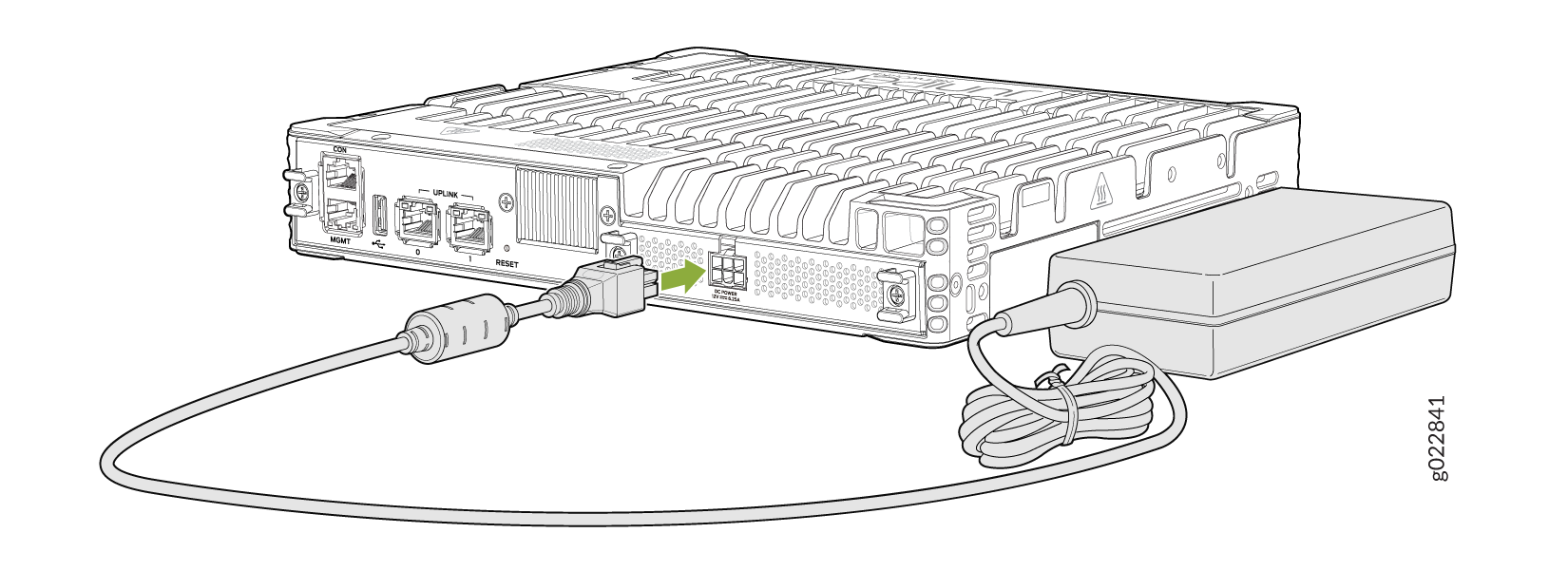
To connect AC power to an EX4100-F-12P and EX400-F-12T switch:
-
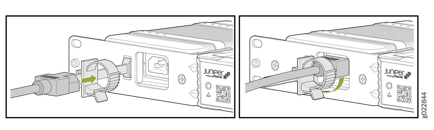
Insert the power cord coupler firmly into the power cord inlet of the power
supply adaptor. See Figure 5.
Figure 5: Connecting an AC Power Cord Retainer Clip to the AC Power Cord Inlet of an EX4100-F-12P and EX4100-F-12T Switch
-
Insert the power cord that is permanently attached to the power supply
adaptor, to the DC inlet of the switch. See Figure 6 and Figure 7.
Figure 6: Connect Power Supply Adaptor to DC Inlet of the EX4100-F-12P Switch
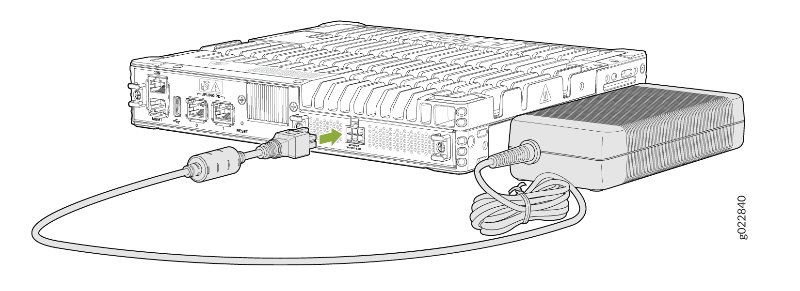 Figure 7: Connect Power Supply Adaptor to DC Inlet of the EX4100-F-12T Switch