EX4100-F Models and Specifications
The EX4100-F (fixed-form) switch models have either built-in power supplies and fans or fanless models using external power supply adaptors.
Let's take a look at the different EX4100-F models and their specifications.
|
Fanless models using external power supply adaptors |
Models with built-in fans and power supplies |
|---|---|
EX4100-F-12P
Components on the Front and Rear Panels of EX4100-F-12P Switches
Figure 1 shows the front view of an EX4100-F-12P switch.

Figure 2 shows the rear view of an EX4100-F-12P switch.

Figure 3 shows the components on the front panel of the EX4100-F-12P switch.
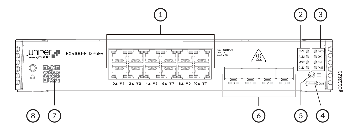
1 — 10/100/1000BASE-T RJ-45 network ports. These ports in EX4100-F-12P switches support PoE+ (30W by default). | 5 — Factory Reset/Mode button |
2 — Chassis status LEDs (labeled SYS, ALM, MST, and CLD) | 6 — 10 GE SFP+ Virtual Chassis ports |
3 — Port mode LEDs (labeled SPD, DX, EN and PoE) | 7 — Claim Code label |
4 — RS232 to USB Type-C console port | 8 — Electrostatic discharge (ESD) point |
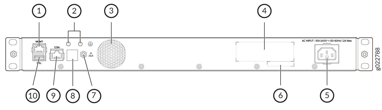
Figure 4 shows the components on the rear panel of the EX4100-F-12P switch.
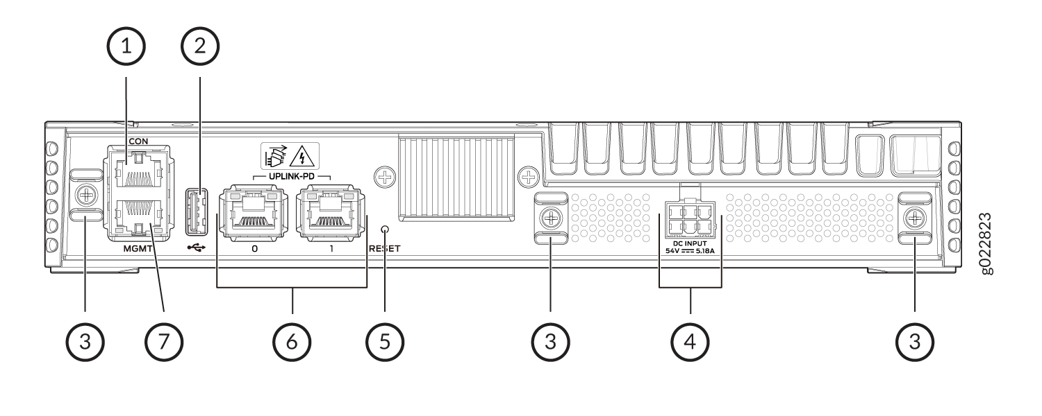
1 — RJ-45 console port (labeled CON) | 5 — Reset button |
2 — USB 2.0 Type-A port | 6 — 1/2.5/5/10 GE BASE-T RJ-45 uplink ports |
3 — Cable Tie mount | 7 — RJ-45 management port (labeled MGMT) |
4 — DC power inlet |
Table 2 lists the components shipped with EX4100-F-12P switch models.
Table 3 describes the physical specifications and ports of EX4100-F-12P switches.
|
Model Number |
Fan Modules/Built-in Fans |
Power Supply Units/Built-in power supply |
First Junos OS Release |
|---|---|---|---|
|
EX4100-F-12P |
NA. Fanless models with natural convection cooling. |
NA. Uses 280W external adapter. |
22.3R1 |
|
Item |
Description |
|---|---|
|
Chassis Dimensions |
Height - 1.75 in (4.44 cm) Depth - 9.66 in (24.54 cm) |
|
Weight |
3000g |
|
Built-in ports |
|
|
PoE ports |
12 - PoE+ (30W by default) |
EX4100-F-12T
Components on the Front and Rear Panels of EX4100-F-12T Switches
Figure 5 shows the front view of an EX4100-F-12T switch.

Figure 6 shows the rear view of an EX4100-F-12T switch.

Figure 7 shows the components on the front panel of the EX4100-F-12T switch.
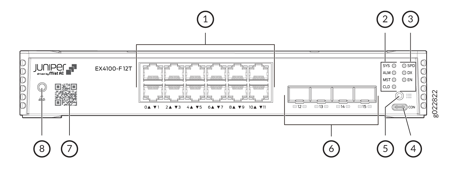
1 — 10/100/1000BASE-T RJ-45 non-PoE network ports. | 5 — Factory Reset/Mode button |
2 — Chassis status LEDs (labeled SYS, ALM, MST, and CLD) | 6 — 10 GE SFP+ Virtual Chassis ports |
3 — Port mode LEDs (labeled SPD, DX, and EN) | 7 — Claim Code label |
4 — RS232 to USB Type-C console port | 8 — Electrostatic discharge (ESD) point |
Figure 8 shows the components on the rear panel of the EX4100-F-12T switch.
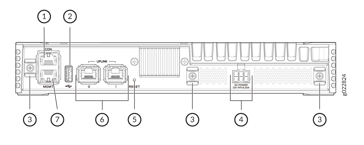
1 — RJ-45 console port (labeled CON) | 5 — Reset button |
2 — USB 2.0 Type-A port | 6 — 1/2.5/5/10 GE BASE-T RJ-45 uplink ports |
3 — Cable Tie mount | 7 — RJ-45 management port (labeled MGMT) |
4 — DC power inlet |
Table 4 lists the components shipped with EX4100-F-12T switch models.
Table 5 describes the physical specifications and ports of EX4100-F-12T switches.
|
Model Number |
Fan Modules/Built-in Fans |
Power Supply Units/Built-in power supply |
First Junos OS Release |
|---|---|---|---|
|
EX4100-F-12T |
NA. Fanless models with natural convection cooling. |
NA. Uses 75W external adapter. |
22.3R1 |
|
Item |
Description |
|---|---|
|
Chassis Dimensions |
Height - 1.75 in (4.44 cm) Depth - 9.66 in (24.54 cm) |
|
Weight |
2700g |
|
Built-in ports |
|
|
PoE ports |
0 |
EX4100-F-24P
Components on the Front and Rear Panels of EX4100-F-24P Switches
Figure 9 shows the front view of an EX4100-F-24P switch.
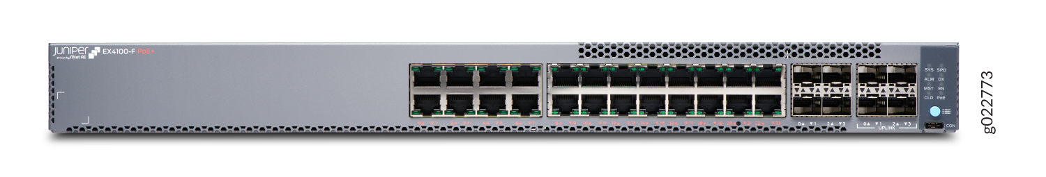
Figure 10 shows the rear view of the EX4100-F-24P switch with 24 ports.
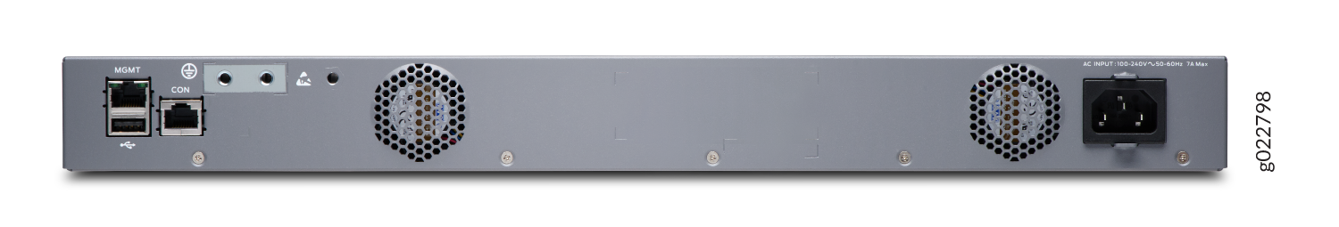
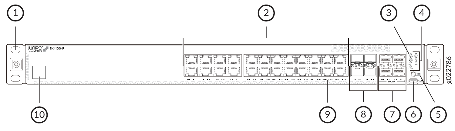
Figure 11 shows the components on the front panel of the EX4100-F-24P switch.
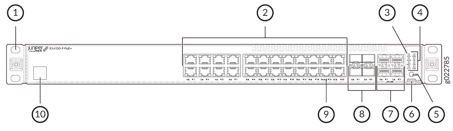
1 — Front mounting brackets | 6 — RS232 to USB Type-C console port |
2 — 10/100/1000BASE-T RJ-45 network ports. These ports in EX4100-F-24P support PoE+ (30 W by default). | 7 — 10 GE SFP+ Uplink ports |
3 — Chassis status LEDs (labeled SYS, ALM, MST, and CLD) | 8 — 1/10 GE SFP+ Virtual Chassis ports |
4 — Port mode LEDs (labeled SPD, DX, EN and PoE) | 9 — Reset button |
5 — Factory Reset/Mode button | 10 — Claim Code label |
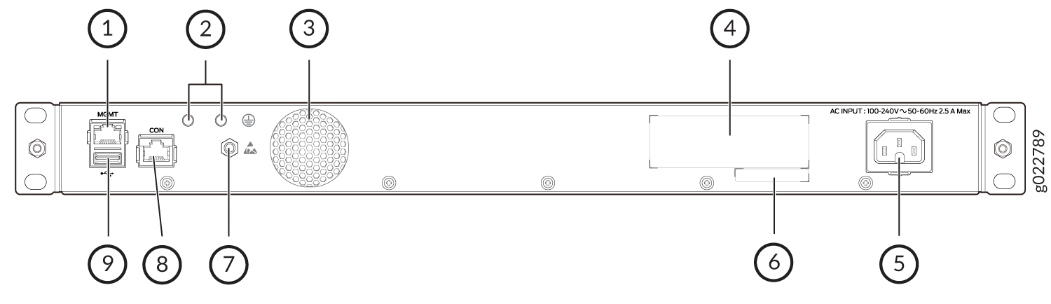
Figure 12 shows the components on the rear panel of EX4100-F-24P switch.
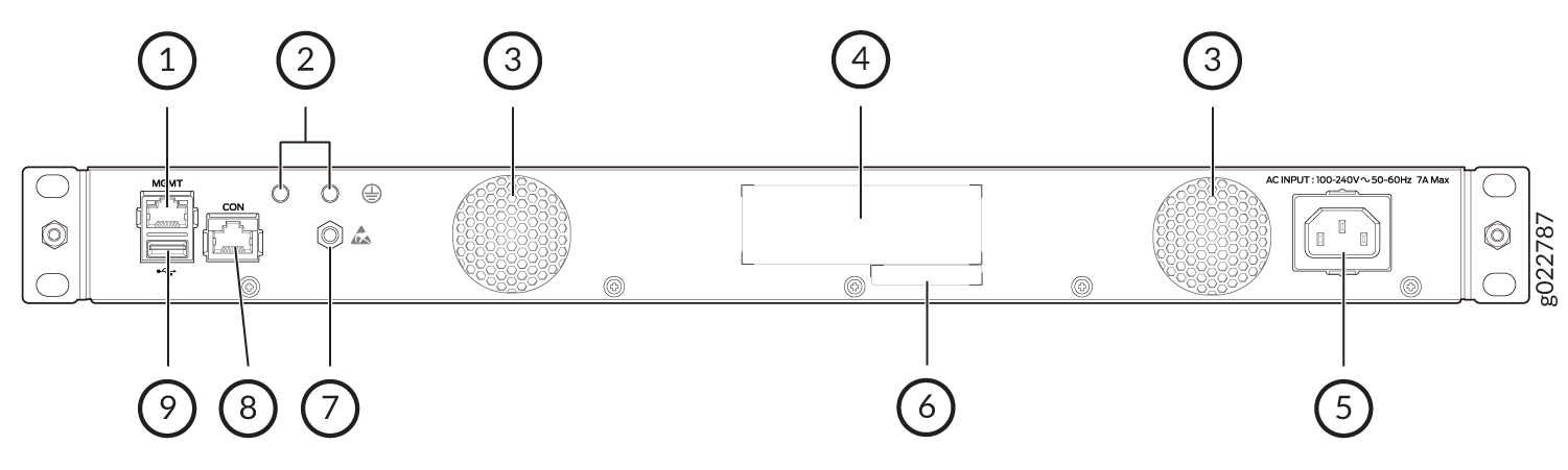
1 — RJ-45 management port (labeled MGMT) | 6 — CLEI code label |
2 — Protective earthing terminal | 7 — Electrostatic discharge (ESD) point |
3 — Built-in fan modules | 8 — RJ-45 console port (labeled CON) |
4 — Serial number | 9 — USB 2.0 Type-A port |
5 — AC power supply socket |
Table 6 lists the components shipped with EX4100-F-24P switch models.
Table 7 describes the physical specifications and ports of EX4100-F-24P switches.
|
Model Number |
Built-in Fans |
Built-in power supply |
First Junos OS Release |
|---|---|---|---|
|
EX4100-F-24P |
Two built-in fan units with front-to-back airflow. |
Built-in 450 W AC power supply |
22.2R1 |
|
Item |
Description |
|---|---|
|
Chassis Dimensions |
Height - 1.72 in (4.37 cm) Depth - 12.2 in (31.13 cm) |
|
Weight |
4745g |
|
Built-in ports |
|
|
PoE ports |
24 - PoE+ (30 W by default) |
EX4100-F-24T
Components on the Front and Rear Panels of EX4100-F-24T Switches
Figure 13 shows the front view of an EX4100-F-24T switch.
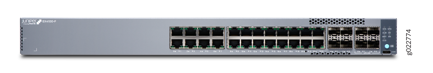
Figure 14 shows the rear view of the EX4100-F-24T switch with 24 ports.
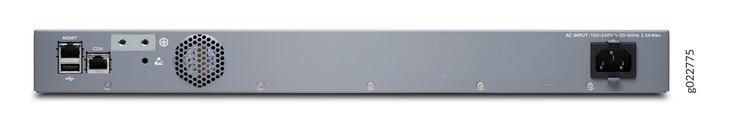
Figure 15 shows the components on the front panel of the EX4100-F-24T switch.
1 — Front mounting brackets | 6 — RS232 to USB Type-C console port |
2 — 10/100/1000BASE-T RJ-45 non-PoE network ports. | 7 — 10 GE SFP+ Uplink ports |
3 — Chassis status LEDs (labeled SYS, ALM, MST, and CLD) | 8 — 1/10 GE SFP+ Virtual Chassis ports |
4 — Port mode LEDs (labeled SPD, DX, and EN) | 9 — Reset button |
5 — Factory Reset/Mode button | 10 — Claim Code label |
Figure 16 shows the components on the rear panel of EX4100-F-24T switch.
1 — RJ-45 management port (labeled MGMT) | 6 — CLEI code label |
2 — Protective earthing terminal | 7 — Electrostatic discharge (ESD) point |
3 — Built-in fan module | 8 — RJ-45 console port (labeled CON) |
4 — Serial number | 9 — USB 2.0 Type-A port |
5 — AC power supply socket |
Table 8 lists the components shipped with EX4100-F-24T switch models.
Table 9 describes the physical specifications and ports of EX4100-F-24T switches.
|
Model Number |
Built-in Fans |
Built-in power supply |
First Junos OS Release |
|---|---|---|---|
|
EX4100-F-24T |
One built-in fan with front-to-back airflow |
Built-in 65 W AC power supply |
22.2R1 |
|
Item |
Description |
|---|---|
|
Chassis Dimensions |
Height - 1.72 in (4.37 cm) Depth - 10.1 in (25.65 cm) |
|
Weight |
3520g |
|
Built-in ports |
|
|
PoE ports |
0 |
EX4100-F-48P
Components on the Front and Rear Panels of EX4100-F-48P Switches
Figure 17 shows the front view of an EX4100-F-48P switch.
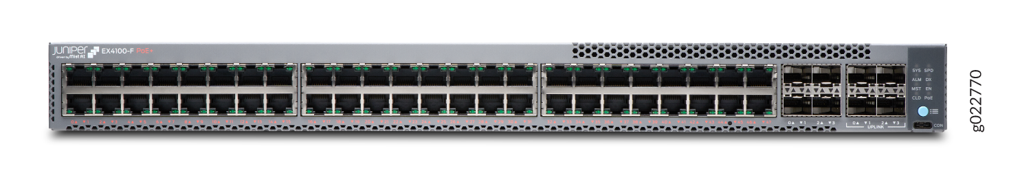
Figure 18 shows the rear view of the EX4100-F-48P switch with 48 ports.
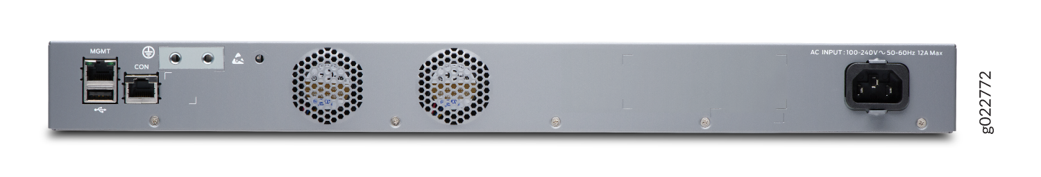
Figure 19 shows the components on the front panel of the EX4100-F-48P switch.

1 — Front mounting brackets | 6 — RS232 to USB Type-C console port |
2 — 10/100/1000BASE-T RJ-45 network ports. These ports support in EX4100-F-48P support PoE+ (30 W by default). | 7 — 10 GE SFP+ Uplink ports |
3 — Chassis status LEDs (labeled SYS, ALM, MST, and CLD) | 8 — 1/10 GE SFP+ Virtual Chassis ports |
4 — Port mode LEDs (labeled SPD, DX, EN and PoE) | 9 — Reset button |
5 — Factory Reset/Mode button |
Figure 20 shows the components on the rear panel of EX4100-F-48P switch.
1 — RJ-45 management port (labeled MGMT) | 6 — CLEI code label |
2 — Protective earthing terminal | 7 — Electrostatic discharge (ESD) point |
3 — Built-in fan modules | 8 — Claim Code label |
4 — Serial number | 9 — RJ-45 console port (labeled CON) |
5 — AC power supply socket | 10 — USB 2.0 Type-A port |
Table 10 lists the components shipped with EX4100-F-48P switch models.
Table 11 describes the physical specifications and ports of EX4100-F-48P switches.
|
Model Number |
Built-in Fans |
Built-in power supply |
First Junos OS Release |
|---|---|---|---|
|
EX4100-F-48P |
Two built-in fan units with front-to-back airflow. |
Built-in 850 W AC power supply |
22.2R1 |
|
Item |
Description |
|---|---|
|
Chassis Dimensions |
Height - 1.72 in (4.37 cm) Depth - 12.2 in (31.13 cm) |
|
Weight |
5200g |
|
Built-in ports |
|
|
PoE ports |
48 PoE+ (30 W by default) |
EX4100-F-48T
Components on the Front and Rear Panels of EX4100-F-48T Switches
Figure 21 shows the front view of an EX4100-F-48T switch.
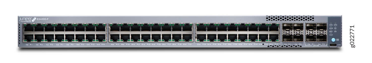
Figure 22 shows the rear view of the EX4100-F-48T switch with 24 ports.
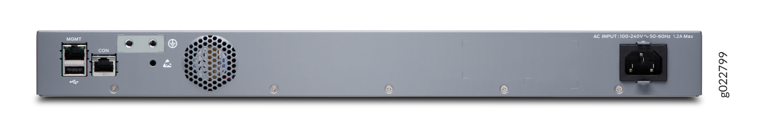
Figure 23 shows the components on the front panel of the EX4100-F-48T switch.
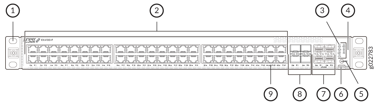
1 — Front mounting brackets | 6 — RS232 to USB Type-C console port |
2 — 10/100/1000BASE-T RJ-45 non-PoE network ports. | 7 — 10 GE SFP+ Uplink ports |
3 — Chassis status LEDs (labeled SYS, ALM, MST, and CLD) | 8 — 1/10 GE SFP+ Virtual Chassis ports |
4 — Port mode LEDs (labeled SPD, DX, and EN) | 9 — Reset button |
5 — Factory Reset/Mode button |
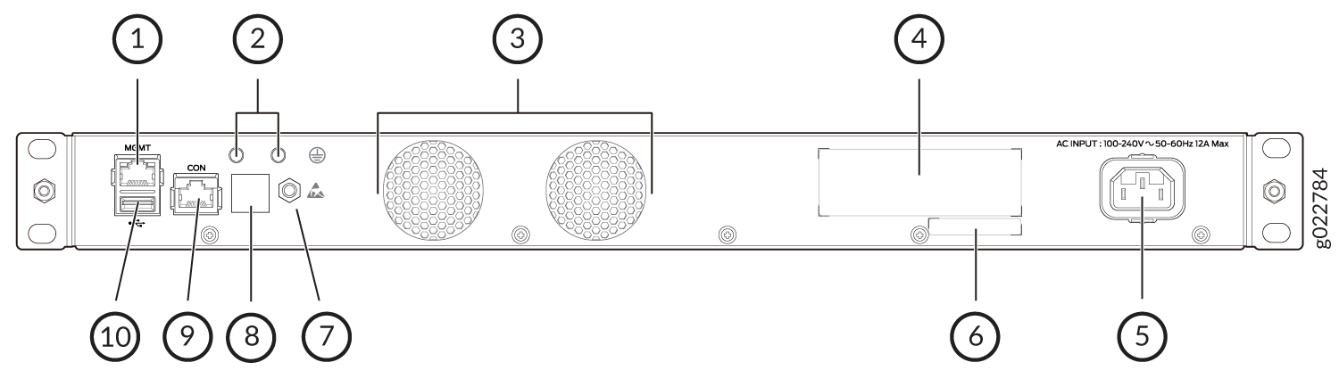
Figure 24 shows the components on the rear panel of EX4100-F-48T switch.
1 — RJ-45 management port (labeled MGMT) | 6 — CLEI code label |
2 — Protective earthing terminal | 7 — Electrostatic discharge (ESD) point |
3 — Built-in fan module | 8 — Claim Code label |
4 — Serial number | 9 — RJ-45 console port (labeled CON) |
5 — AC power supply socket | 10 — USB 2.0 Type-A port |
Table 12 lists the components shipped with EX4100-F-48T switch models.
Table 13 describes the physical specifications and ports of EX4100-F-48T switches.
|
Model Number |
Built-in Fans |
Built-in power supply |
First Junos OS Release |
|---|---|---|---|
|
EX4100-F-48T |
One built-in fan with front-to-back airflow |
Built-in 90 W AC power supply |
22.2R1 |
|
Item |
Description |
|---|---|
|
Chassis Dimensions |
Height - 1.72 in (4.37 cm) Depth - 10.1 in (25.65 cm) |
|
Weight |
3885g |
|
Built-in ports |
|
|
PoE ports |
0 |