Help us improve your experience.

Let us know what you think.

Do you have time for a two-minute survey?


Cooling System and Airflow in an EX4000 Switch

EX4000-8P, EX4000-12T, EX4000-12P, and EX4000-12MP switches have fanless convection cooling. EX4000-24P and EX4000-24MP have 2 fixed inbuilt fans each. EX4000-48P and EX4000-48MP have 3 fixed inbuilt fans each. EX4000-24T and EX4000-48T have 1 fixed inbuilt fan each. The airflow direction of the fans is front-to-back.

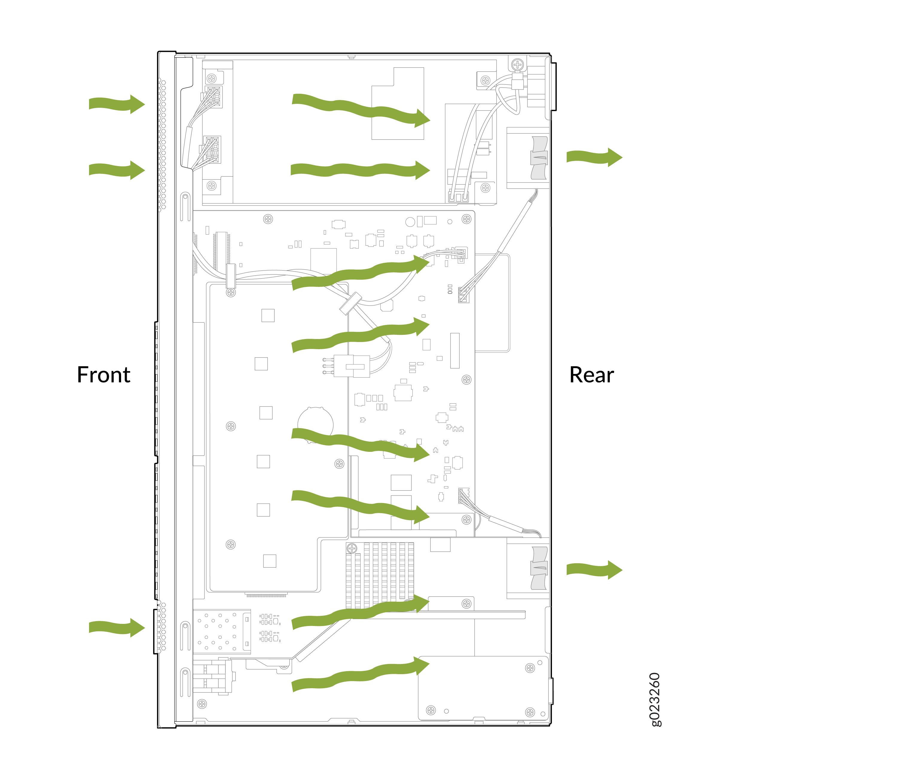
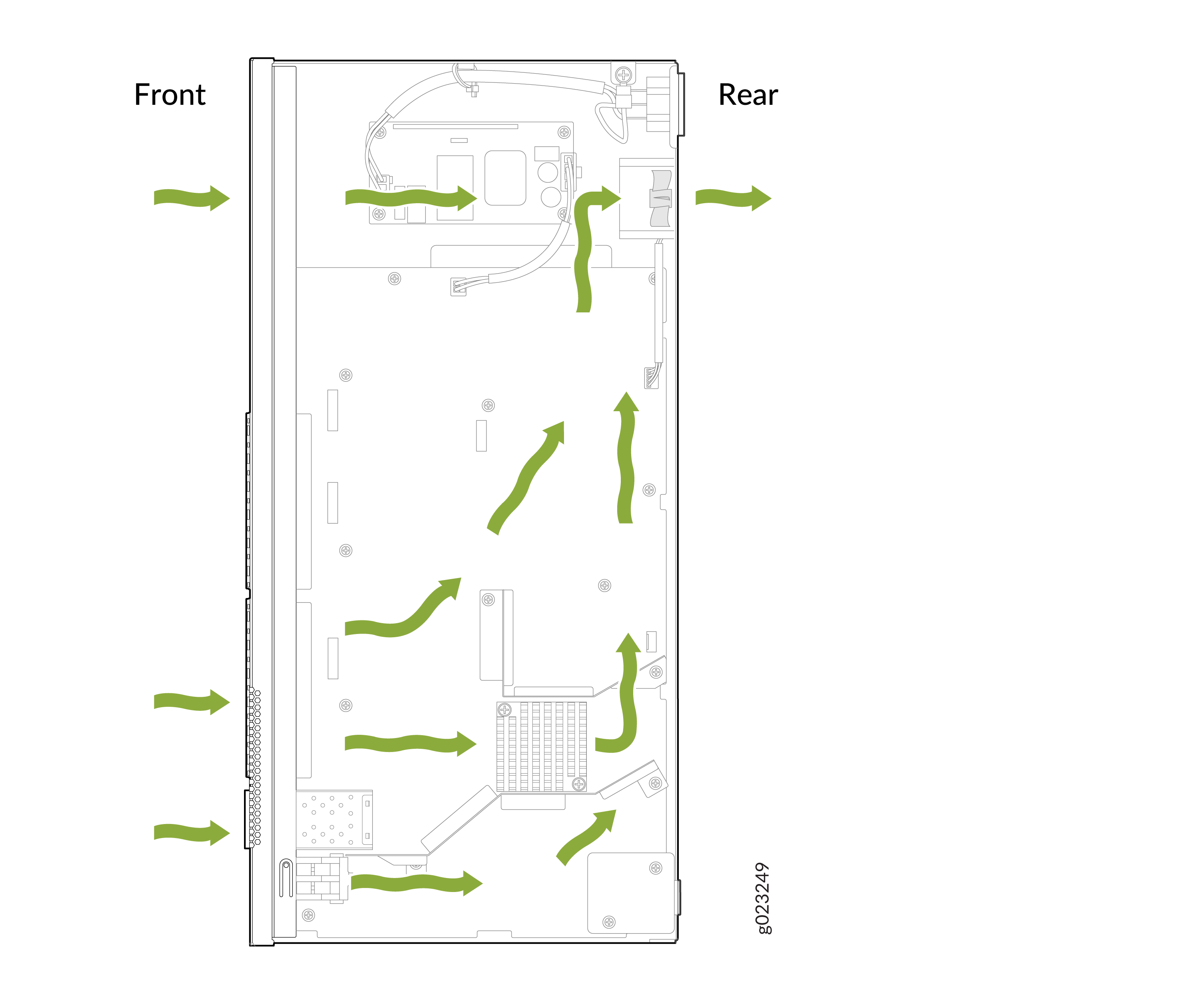
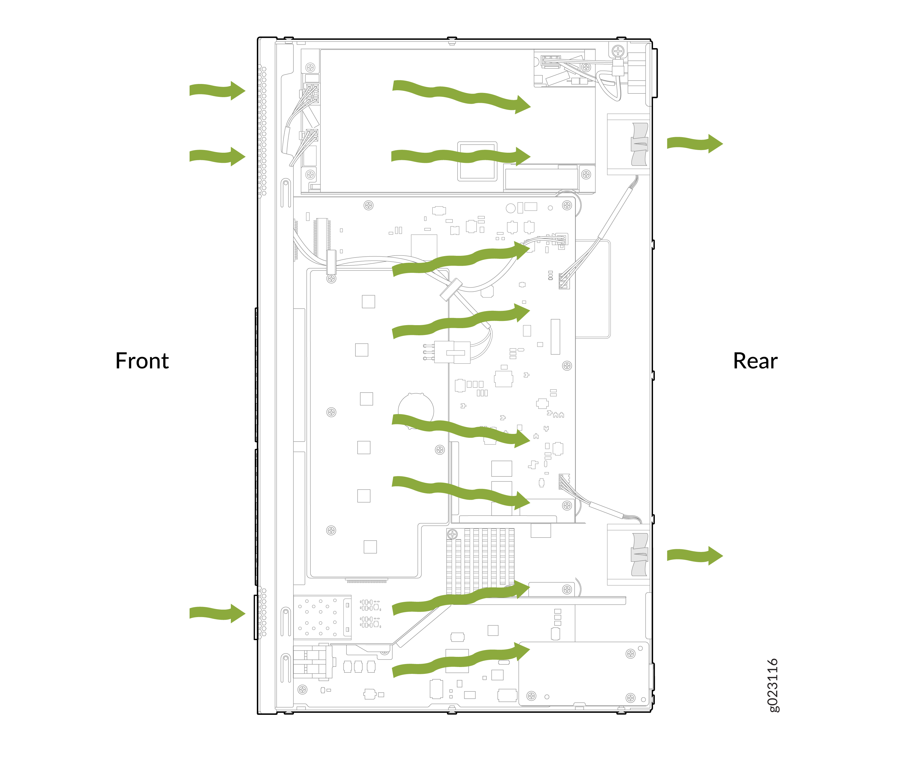
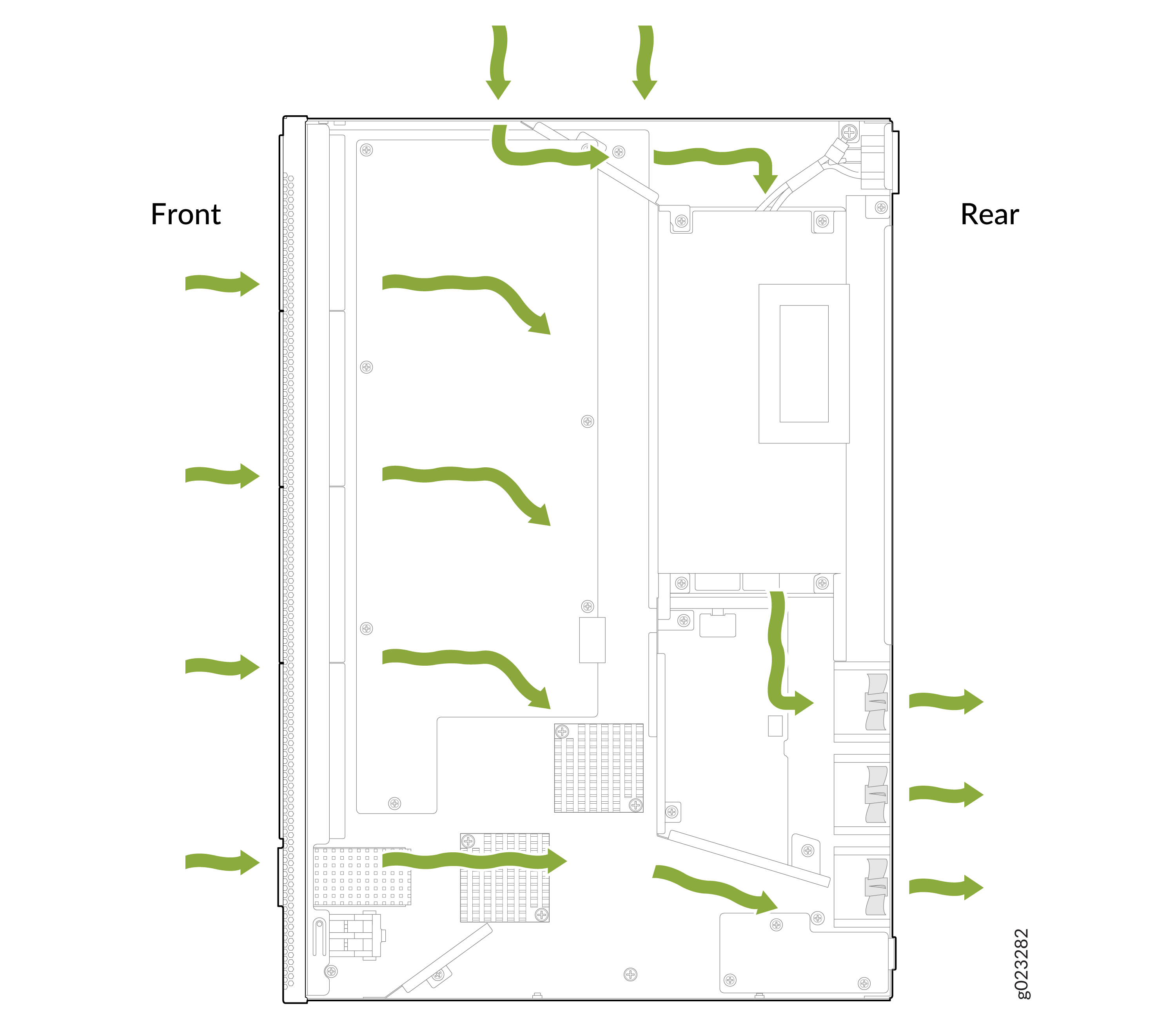
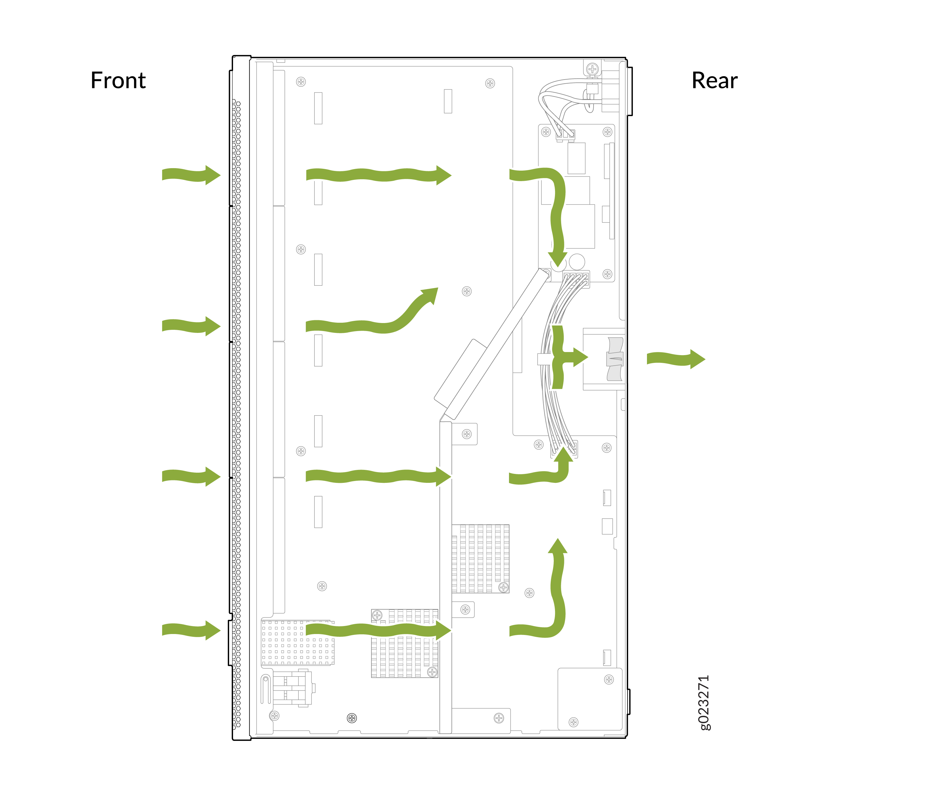
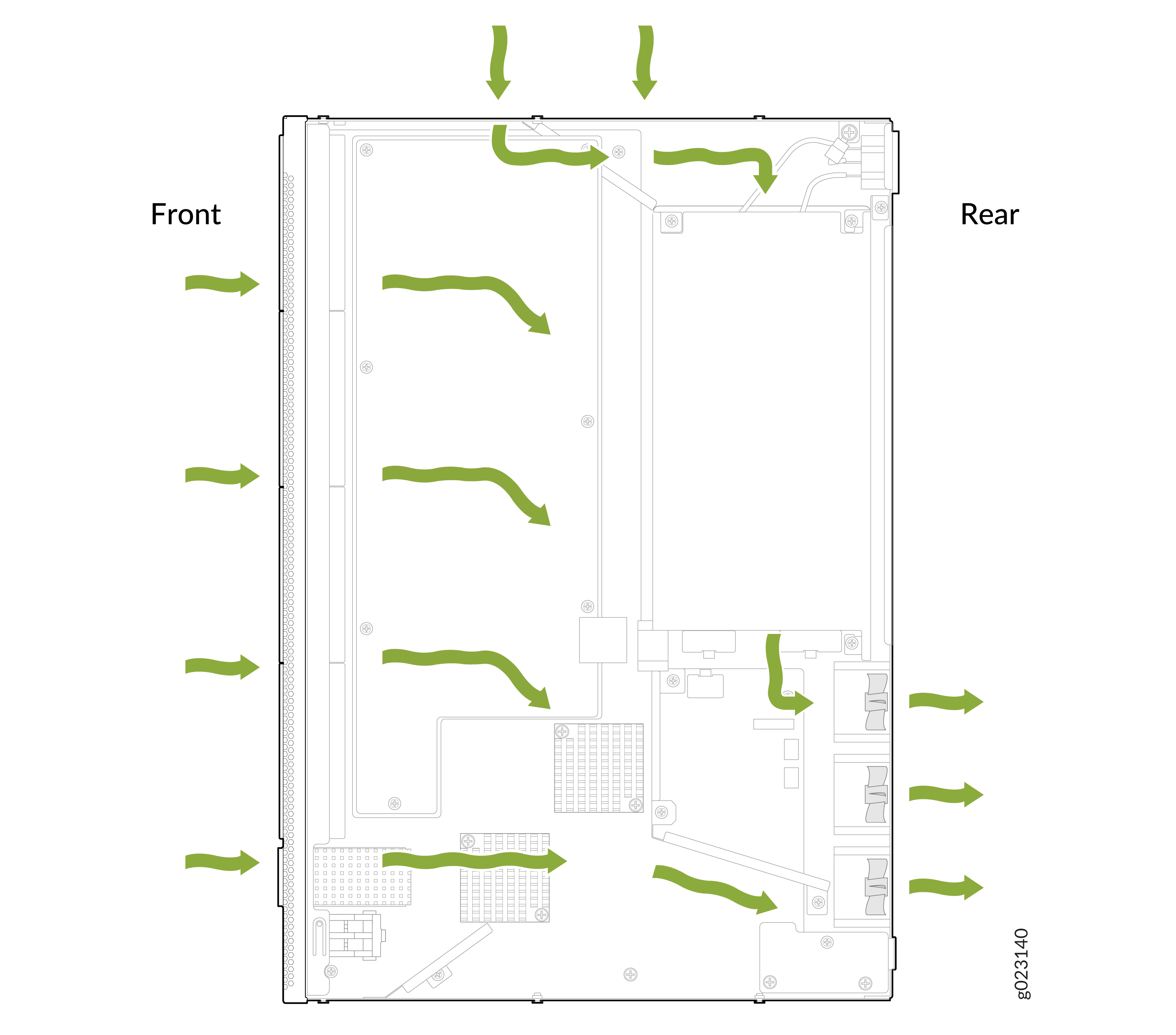
EX4000 Switches with Front-to-Back Airflow

In EX4000 switch models with front-to-back airflow, air enters through vents on the front panel to cool the chassis. The hot air then exits through the vents on the rear panel.

Note:

The front side of a switch is the side where the ports are located. The rear side is where the fans are located.

Figure 1: Front-to-Back Airflow Through the EX4000-24P Switch Chassis Airflow pattern inside a computer chassis with green arrows indicating air movement from front to rear for cooling.
Figure 2: Front-to-Back Airflow Through the EX4000-24T Switch Chassis Diagram of airflow in a computer case showing cool air entering from front and hot air exiting from rear for optimal cooling.
Figure 3: Front-to-Back Airflow Through the EX4000-24MP Switch Chassis Airflow pattern inside a computer chassis with green arrows indicating air movement from front to rear for cooling.
Figure 4: Front-to-Back Airflow Through the EX4000-48P Switch Chassis Diagram of airflow in a computer server with green arrows showing air entering from the front and exiting at the rear for cooling.
Figure 5: Front-to-Back Airflow Through the EX4000-48T Switch Chassis Airflow pattern in a computer chassis with green arrows showing air entering from the front and exiting at the rear.
Figure 6: Front-to-Back Airflow Through the EX4000-48MP Switch Chassis Airflow diagram showing green arrows moving from front to rear of a computer chassis for cooling internal components.

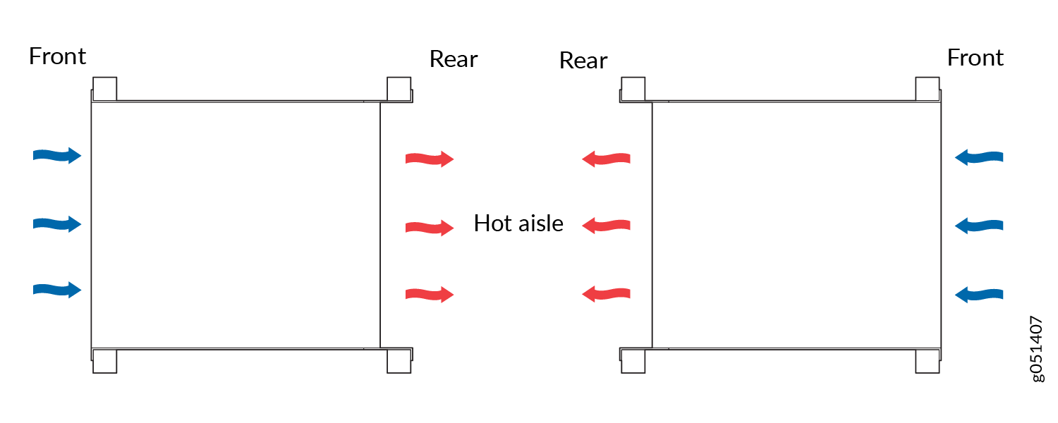
How to Position the Switch

Position the switch with front-to-back airflow in such a manner that the air flow out direction of the fans is directed to the hot aisle.

Figure 7: Deployment of Switches with Front-to-Back Airflow Through the Switch Chassis Deployment of Switches with Front-to-Back Airflow Through the Switch Chassis