EX2300 Chassis
Chassis Status LEDs in EX2300 Switches
The front panel of EX2300 switches except the EX2300-24MP and EX2300-48MP models has three chassis status LEDs labeled SYS, ALM, and MST. See Figure 1 and Figure 2.
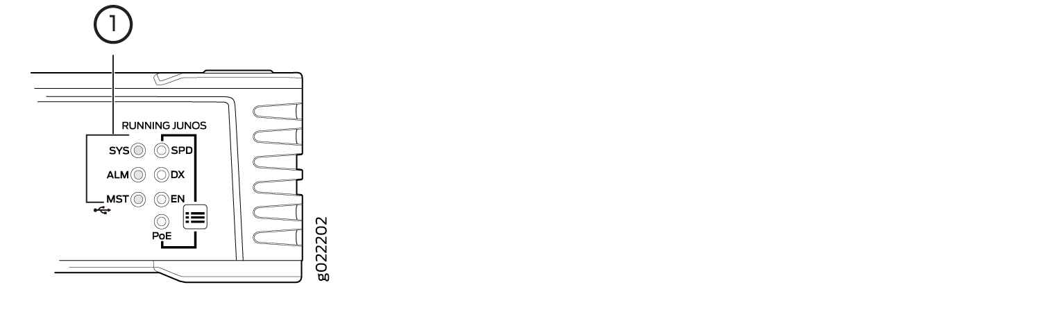
1 — Chassis Status LEDs |
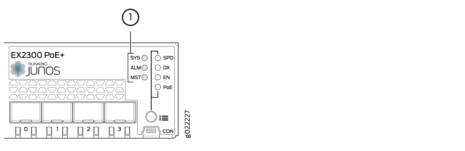
1 — Chassis Status LEDs |
Table 1 describes the chassis status LEDs in EX2300 switches except the EX2300-24MP and EX2300-48MP models, their colors and states, and the status they indicate.
|
LED Label |
Color |
State and Description |
|---|---|---|
|
SYS |
Green |
|
|
ALM |
Red |
There is a major alarm. Note:
When you connect power to the switch, the alarm LED (ALM) glows red. This behavior is normal. Plugging an active Ethernet cable into the management port (MGMT) on the switch completes the network link and turns off the ALM LED. (See Connect a Device to a Network for Out-of-Band Management.) Connecting the switch to a dedicated management console instead of a network does not affect the ALM LED. The LED remains red until the switch is connected to a network. |
|
Yellow |
There is a minor alarm. Note:
The ALM LED glows yellow if you commit a
configuration to make it active on the switch without creating a
rescue configuration to back it up. To save the most recently
committed configuration as the rescue configuration, enter the
operational mode command |
|
|
Unlit |
There is no alarm or the switch is halted. |
|
|
MST |
Green |
In a standalone EX2300 switch:
In a Virtual Chassis configuration:
|
A major alarm (red) indicates a critical error condition that requires immediate action.
A minor alarm (yellow) indicates a noncritical condition that requires monitoring or maintenance. A minor alarm that is left unchecked might cause interruption in service or performance degradation.
All three LEDs can be lit simultaneously.
On EX2300 switches except the EX2300-24MP and EX2300-48MP models, you can view the colors of the two LEDs remotely through the CLI by issuing the operational mode command show chassis led.
The front panel of EX2300-24MP and EX2300-48MP models has three system LEDs labeled MGT, FAN, and PW. See Figure 3 and Figure 4.
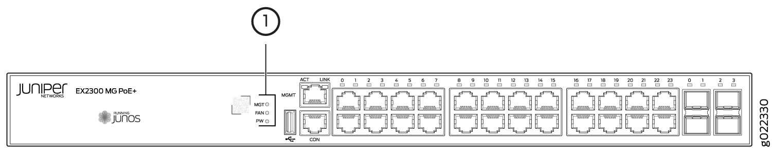
1 — System LEDs |
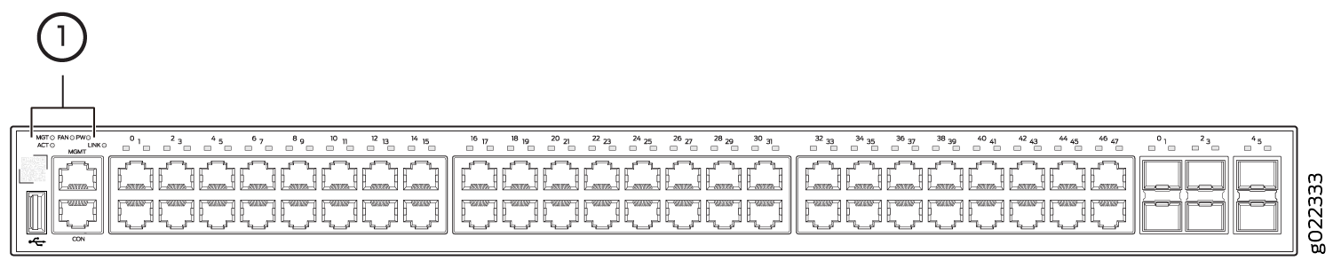
1 — System LEDs |
Table 2 describes the system LEDs in EX2300-24MP and EX2300-48MP models, their colors and states, and the status they indicate.
|
LED Label |
Color |
State and Description |
|---|---|---|
|
MGT |
Green |
|
|
FAN |
Amber—blinking |
At least one of the fans has failed. |
|
Green—on steadily |
The fans are functioning normally. |
|
|
Unlit |
There is no alarm or the switch is powered off or halted. |
|
|
PW |
Green—on steadily |
The power supply is functioning normally. |
|
Amber—blinking |
The supply of PoE power to RJ-45 network ports is disabled and the supply PoE/PoE+ power to devices connected to those ports is disabled. |
|
|
Unlit |
The switch is powered off . |
PW LED stays solid green when switch is halted/powered-off using CLI commands
request system power-off or request system
halt.
See Also
Management Port LEDs in EX2300 Switches
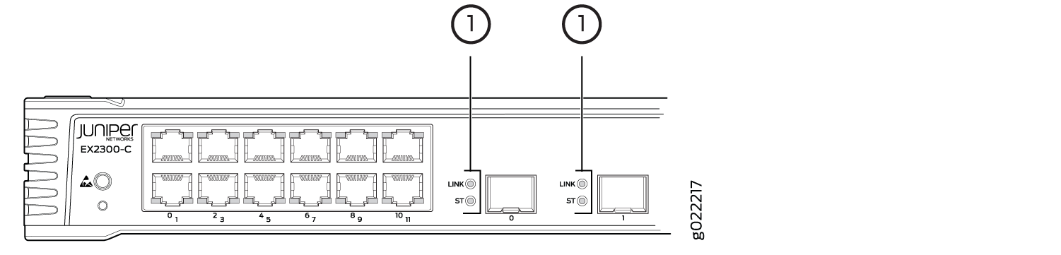
The management port on an EX2300 switch has two LEDs that indicate link/activity and port status. The EX2300 switches except the EX2300-C switch and EX2300-24MP and EX2300-48MP models have the management port on the rear panel; the EX2300-C switches and EX2300-24MP and EX2300-48MP models have the management port on the front panel. See Figure 5, Figure 6, Figure 7, and Figure 8.
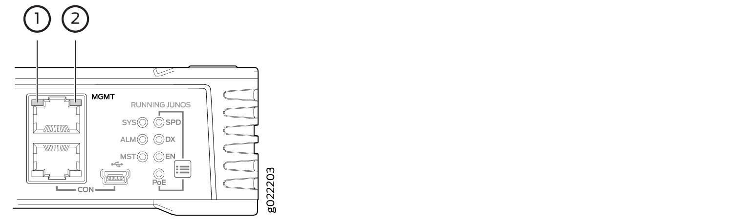
1 — Link/Activity LED | 2 — Status LED |
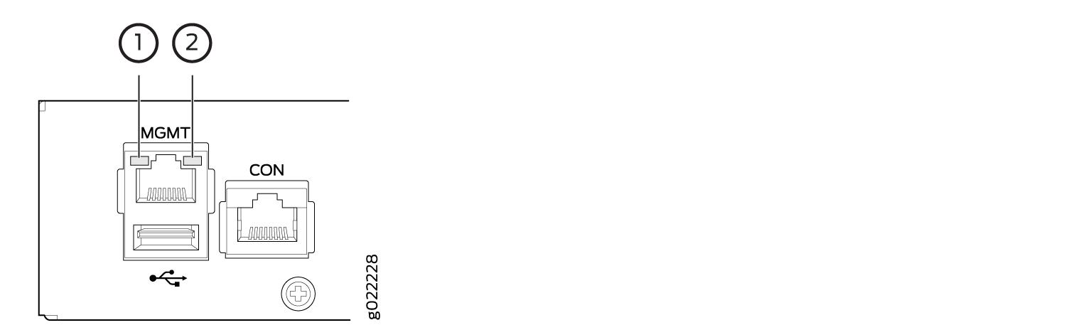
1 — Link/Activity LED | 2 — Status LED |
Table 3 describes the Link/Activity LED on the management port on EX2300 switches except the EX2300-24MP and EX2300-48MP switch models.
|
LED |
Color |
State and Description |
|---|---|---|
|
Link/Activity |
Green |
|
Table 4 describes the Status LED on the management port on EX2300 switches except the EX2300-24MP and EX2300-48MP switch models.
|
LED |
Color |
State and Description |
|---|---|---|
|
Status |
Green |
Indicates the speed. The speed indicators are:
|
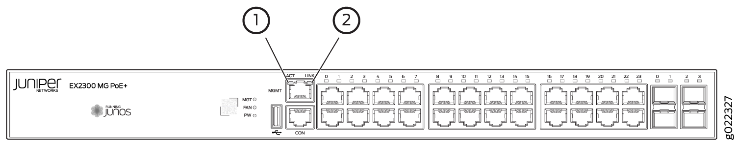
1 — Link LED | 2 — Activity LED |
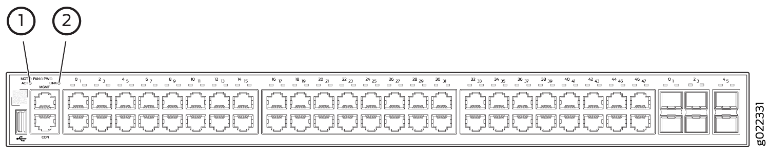
1 — Link LED | 2 — Activity LED |
Table 5 describes the Link LED on the management port on EX2300-24MP and EX2300-48MP switch models.
|
LED |
Color |
State and Description |
|---|---|---|
|
Link |
Green |
|
Table 6 describes the Activity LED on the management port on EX2300-24MP and EX2300-48MP switch models.
|
LED |
Color |
State and Description |
|---|---|---|
|
Activity |
Green |
|
See Also
RJ-45 Network Port LEDs and Uplink Port LEDs in EX2300 Switches
Each RJ-45 network port and uplink port on the front panel of EX2300 switches except the EX2300-24MP and EX2300-48MP switch models have two LEDs that indicate link/activity and port status. See Figure 9, Figure 10, and Figure 11.
1 — LEDs on the uplink ports |
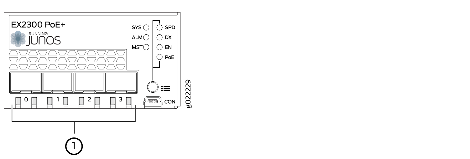
1 — LEDs on the uplink ports |
Table 7 describes the Link/Activity LED on EX2300 switches except the EX2300-24MP and EX2300-48MP models.
|
LED |
Color |
State and Description |
|---|---|---|
|
Link/Activity |
Green |
|
Figure 12 shows the LEDs on EX2300 switches except the EX2300-24MP and EX2300-48MP models that indicate the status of one of the four port parameters—speed, duplex mode, administrative status, and Power over Ethernet (PoE) status. Use the Factory Reset/Mode button on the far right side of the front panel to toggle the Status LED to show the different port parameters for RJ-45 network ports. You can tell which port parameter is indicated by the Status LED by looking at which port status mode LED (SPD, DX, EN, and PoE) is lit. The LED labeled PoE is not available on switch models with RJ-45 network ports that do not provide PoE.
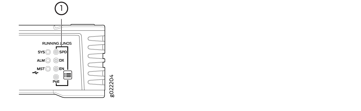
1 — Port mode LEDs |
Table 8 describes the Status LED on the RJ-45 network ports in EX2300 switches except the EX2300-24MP and EX2300-48MP switch models.
|
Port Parameters |
State and Description |
|---|---|
|
Speed (SPD) |
Indicates the speed. The speed indicators are:
|
|
Duplex mode (DX) Note:
On EX2300-24T switches, only the ports labeled 0/0 through 0/15 support half-duplex. On EX2300-48T switches, only the ports labeled 0/0 through 0/15 and 0/24 through 0/39 support half-duplex. |
Indicates the duplex mode. The status indicators are:
|
|
Administrative status (EN) |
Indicates the administrative status. The status indicators are:
|
|
PoE status (PoE) |
Indicates the PoE status. The status indicators are:
Note:
The PoE Status LED is available on the following EX2300 switch models:
|
Starting in Junos OS Release 19.4R1, you can use the
request chassis beacon
command
on EX2300 switches except the EX2300-24MP and EX2300-48MP switch models
to identify the switch or a port on the switch. When you execute the
command, the status LEDs on the RJ-45 network ports blink two times
per second irrespective of the mode the ports are operating in (see How to Locate a Device or Port Using the Chassis
Beacon).
The uplink ports operate in full-duplex mode and PoE is not applicable on uplink ports. The Status LED on uplink ports indicate the Speed (SPD) and Administrative status (EN). Table 9 describes the Status LED on the uplink ports in EX2300 switches except the EX2300-24MP and EX2300-48MP switch models.
|
LED |
State and Description |
|---|---|
|
Status LED |
Indicates the speed and administrative status. The indicators are:
|
On EX2300 switches except the EX2300-24MP and EX2300-48MP models,
you can tell which port parameter is indicated by the Status LED on
RJ-45 network ports and uplink ports by issuing the operational mode
command
            show chassis
led
.
Each RJ-45 network port and uplink port on the front panel of EX2300-24MP and EX2300-48MP switch models has one LED that indicates link/activity. See Figure 13, Figure 14, Figure 15, and Figure 16.
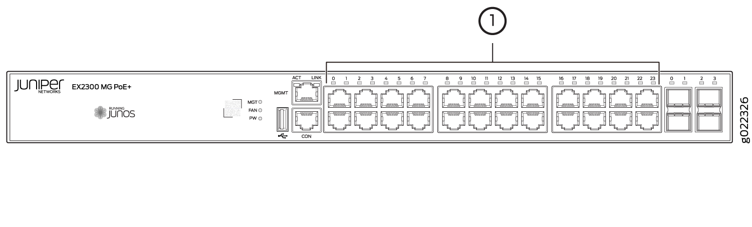
1 — LED on RJ-45 ports |
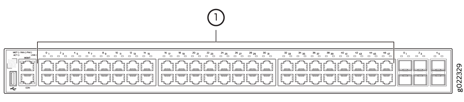
1 — LED on RJ-45 ports |
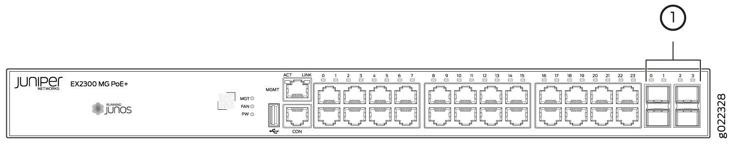
1 — LED on the uplink ports |
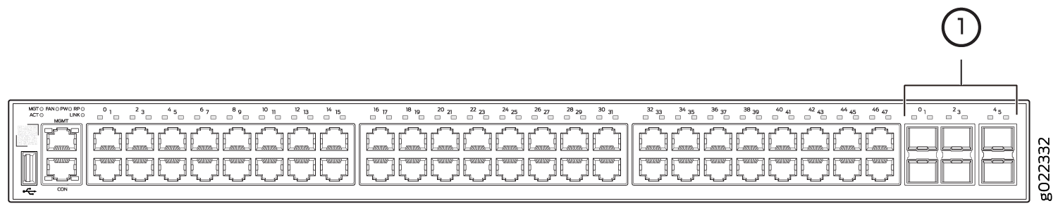
1 — LED on the uplink ports |
Table 10 describes the Link/Activity LED on the RJ-45 network ports and uplink ports in EX2300-24MP and EX2300-48MP models.
|
LED |
Color |
State and Description |
|---|---|---|
|
Link/Activity |
Green |
|
You can tell:
-
The speed and duplex mode at which a port is operating in by issuing the command show interfaces media.
-
The administrative status on each port by issuing the command show interfaces terse.
-
The PoE status on each port by issuing the command show poe interface.